

Page 1
Instruction Sheet For:
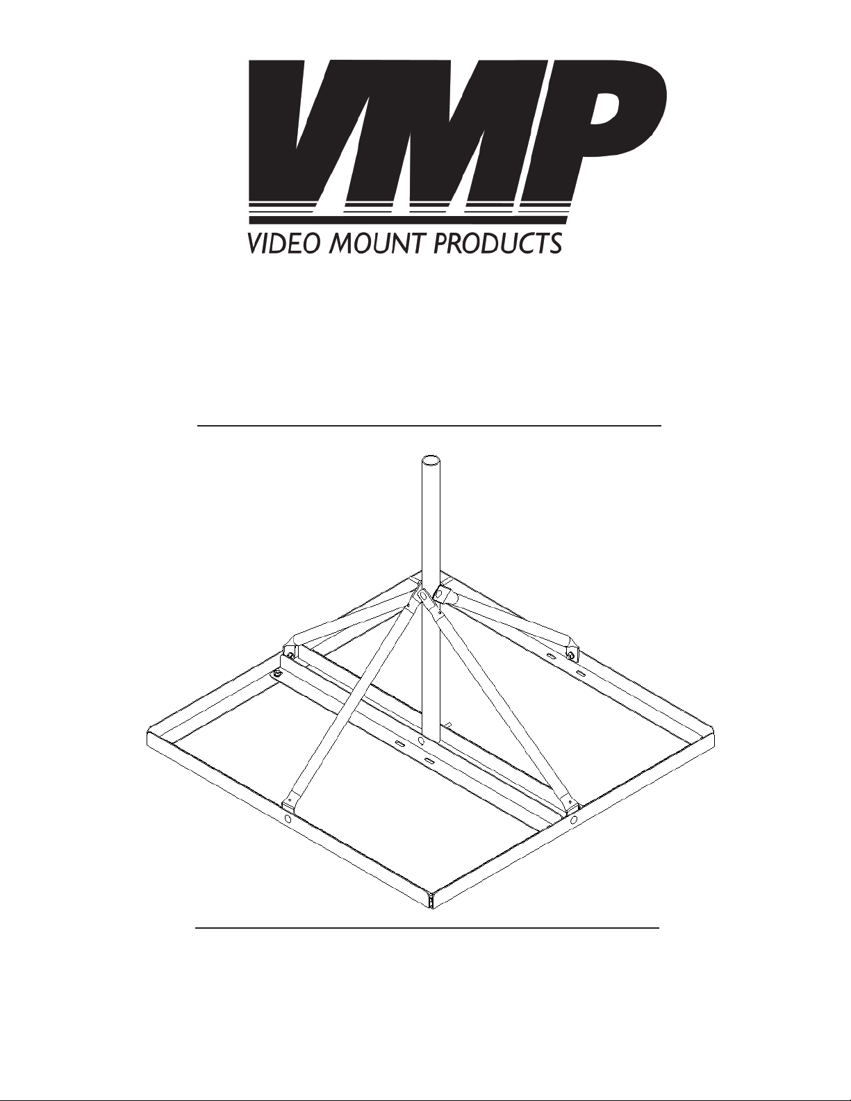
FRM SERIES
For more information, please contact us at:
345 Log Canoe Circle, Stevensville, Maryland 21666
Toll Free: 877.281.2169 Phone: 410.643.6390 Fax: 410.643.6615
www.videomount.com
Page 2
6
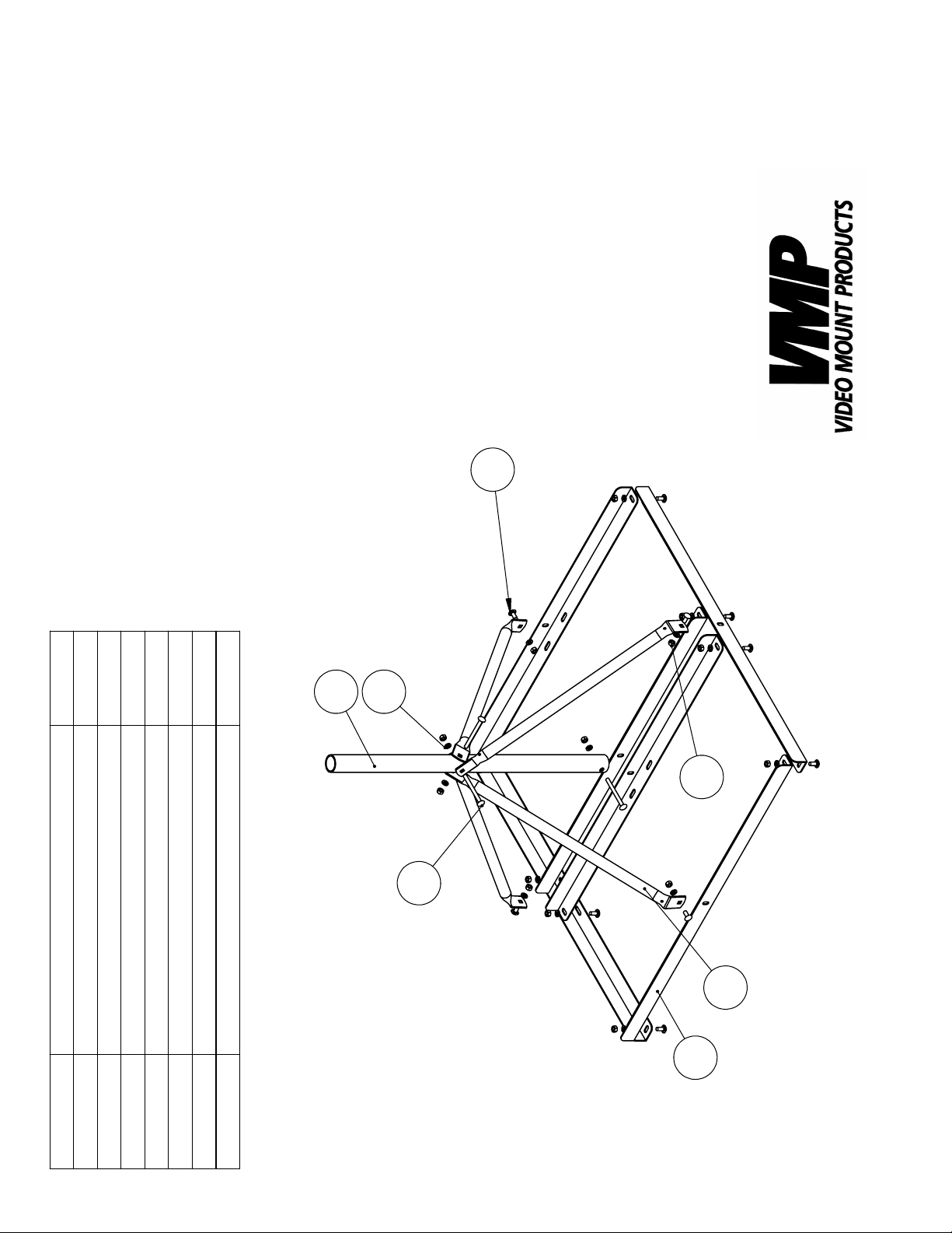
QTY.
7
FRM-Series
1
4
3
15
15
12
2
5
6
4
Stand Bar
DESCRIPTION
ITEM NO.
Support Arm
Support Tube
Screw 5/16"-18UNC*L3.5"
1
2
3
4
Lock Washer 5/16"
Hex Nut 5/16"-18UNC
Screw 5/16"*18UNC*L3/4"
5
6
7
3
1
Page 3

Step 2: Assembling the sled
Step 1
Before starting, lay out all parts to your mount and match them to
the parts list provided. Verify that you have all your parts before
attempting to assemble the mount.
Note: It is highly recommended that the installation of this mount
be done by a professional.
Step 2
Assemble the stand bars creating two wells as show in the image to the left using the short screws , lock washers and
nuts .
6
1
7
5
Step 3
Attach the support tube in the center of the middle stand bars
using the long screw , lock washers and nuts .
1
2
4
5
6
Step 4
Locate the holes which are lower on the support tube . Select
two arms and place them so the arms are connecting to
the stand bars that are 90 degrees rotated from the lower set of
holes in the support tube . Use the short screws , lock washer
and nut to attach the arms to the stand bar . Line up
5
the holes on the arms with the lower set of holes in the support
tube and use the long screw , lock washer and nut
to connect them together.
6
3
1
2
6
3
2
4
3
2
7
1
5
Step 3: Attaching the
support tube
Step 4: Attaching the arms
to the lower arms in the
support tube
Page 4

Step 5: Attaching the arms
to the higher arms in the
support tube
Step 5
Locate the holes which are higher on the support tube .
Select two arms and place them so the arms are connecting to the stand bars that are 90 degrees rotated from the
higher set of holes in the support tube . Use the short screws
, lock washer and nut to attach the arms to the
7
stand bar . Line up the holes on the arms with the higher
1 3
set of holes in the support tube and use the long screw
, lock washer and nut to connect them together.
4
3
1
2
5
5
6
2
6
3
2
Step 6
Load ballast (weight placed in the sled to weigh down the nonpenetrating mount) as required for the application. WARNING:
It is highly recommended that you load ballast before attaching any dish or antenna to the non-penetrating roof mount. It is
up to the installer to verify the correct amount of ballast for the
installation. You can use roof pads to protect the surface of the
support surface. It is important that the underlying roof structure
be strong enough to resist whatever forces that may be subjected to it from the antenna/satellite dish system and mount. For
extreme weather conditions it is recommend that this mount be
tethered with a cable. It is up to the installer to verify that the
installation meets all applicable codes and standards. Video
Mount Products does not accept any responsibility for verifying
FRM mounts will work for any given installation.
Step 6: Loading ballast
into the sled
Enjoy Your Mount!
WARNING: The installer must verify the installation meets all
applicable codes and survival requirements. Video Mount
Products will not be held liable for the improper use or installation of its products.
 Loading...