

Page 1
FP-MWAB
WARNINGS (continued)
INSTALLATION
FULL MOTION WALL MOUNT
FOR LCD, PLASMA, and LED DISPLAYS
INSTRUCTION MANUAL
SPECIFICATIONS
Display Size: 27” to 42”
Maximum Load: 80 lbs
Mounting Pattern: Up to 450 mm x 400 mm
Tilt Range: +15° to -15°
Prole: 5.5” to 16.5”
BOX CONTENTS
Full-motion Mount (x1)
Mount Arm (x2)
WARNINGS
1
Read these instructions before you begin. If you are
unsure of any part of the process, contact a professional
contractor or installer for assistance. Improper installation
can result in injury or damage.
2
The wall or mounting surface must be capable of
supporting the combined weight of the mount and the
display; if not, the structure must be reinforced.
3
Locate pipes, wires, or any other hazards in the wall where
you wish to install the mount before drilling.
4
Safety gear and proper tools must be used. Failure to do so
can result in injury or damage.
5
A minimum of two people are required for installation. Do
not attempt to install this mount alone under any
circumstances.
6
Follow all instructions and recommendations regarding
adequate ventilation and suitable locations for mounting
your display. Consult the owner‘s manual for your particular
display for more information.
Instruction Manual (x1)
Hardware Kit (x1)
CAUTION: This wall mount is intended for use only with
the maximum weight of 80 lbs. Use with heavier than the
maximum weights indicated may result in instability
causing possible injury.
TOOLS REQUIRED
Phillips Head Screw Driver
Ratchet or Driver with 13 mm (1/2”) Socket
Electric or Portable Drill
6 mm (1/4”) Drill Bit and Stud Finder for Drywall Installation
10 mm (3/8”) Masonry Bit for Concrete Installation
Level
HARDWARE KIT
(A) M8 x 63 Lag Bolt (x4)
(B) Lag Bolt Washer (x4)
(C) Concrete Anchor (x4)
(D) M4 x 12 Screw (x4)
(E) M4 x 20 Screw (x4)
(F) M6 x 12 Screw (x4)
(G) M6 x 30 Screw (x4)
(H) M8 x 12 Screw (x4)
(I) M8 x 30 Screw (x4)
(J) M6 Washer (x4)
(K) Spacer (x8)
(L) Safety Stopper (x2)
(M) S4 Allen Key (x1)
Part 1A – Mounting to the Wall (Drywall)
IMPORTANT! For safety reasons, this mount must be secured to a
wood stud capable of supporting the combined weight of the
mount and display. Do not mount to drywall alone.
1
Use a high quality stud nder to locate a stud where you
wish to install your mount. Mark both edges of the stud to
help identify the exact center.
NOTE: You must use the center of the stud to avoid
cracking or splitting the wood during installation.
2
Place the mount against the wall over the marked stud.
Make sure it is level.
3
While another person holds the mount in position, mark
two locations (one at the top and one at the bottom) for
securing the mount to the wall (see Fig. 1).
4
Set the mount aside and drill a 6 mm (1/4”) pilot hole at
each marked location.
5
Place the mount against the wall over the drilled holes,
making sure the arrow on the mount points up. Attach the
mount to the wall using the lag bolts (A) and lag bolt
washers (B) provided (see Fig. 2). Do not over-tighten
these bolts and do not release the mount until both
bolts are in place. Ensure that the mount remains level
after all bolts are secured.
Fig. 1
Fig. 2
Part 1B – Mounting to the Wall (Concrete)
IMPORTANT! For safety reasons, the concrete wall must be
capable of supporting the combined weight of the mount and the
display. The manufacturer takes no responsibility for failure caused
by walls of insucient strength.
1
Place the mount against the wall in the desired location.
Make sure it is level.
2
While another person holds the mount in place, mark four
locations (two at the top and two at the bottom) for
securing the mount to the wall (see Fig. 3).
Part 1B – Mounting to the Wall (Concrete)
3
Set the mount aside and drill a 10
mm (3/8”) hole at each marked
(continued)
Fig. 3
location. Remove any excess dust
from the holes.
4
Insert a concrete anchor (C) into
each hole so that it is ush with the
concrete surface (see Fig. 4). A
hammer can be used to lightly tap
the anchors into place if necessary.
Fig. 4
NOTE: If the concrete wall is covered
by a layer of plaster or drywall, the
concrete anchor must pass
completely through the layer to rest
ush with the concrete surface.
5
Place the mount against the wall
over the drilled holes, making sure
the arrow on the mount points up.
Fig. 5
Attach the mount to the wall using
the lag bolts (A) and lag bolt
washers (B) provided (see Fig. 5). Do
not over-tighten these bolts and
do not release the mount until all
bolts are in place. Ensure that the
mount remains level after all bolts
are secured.
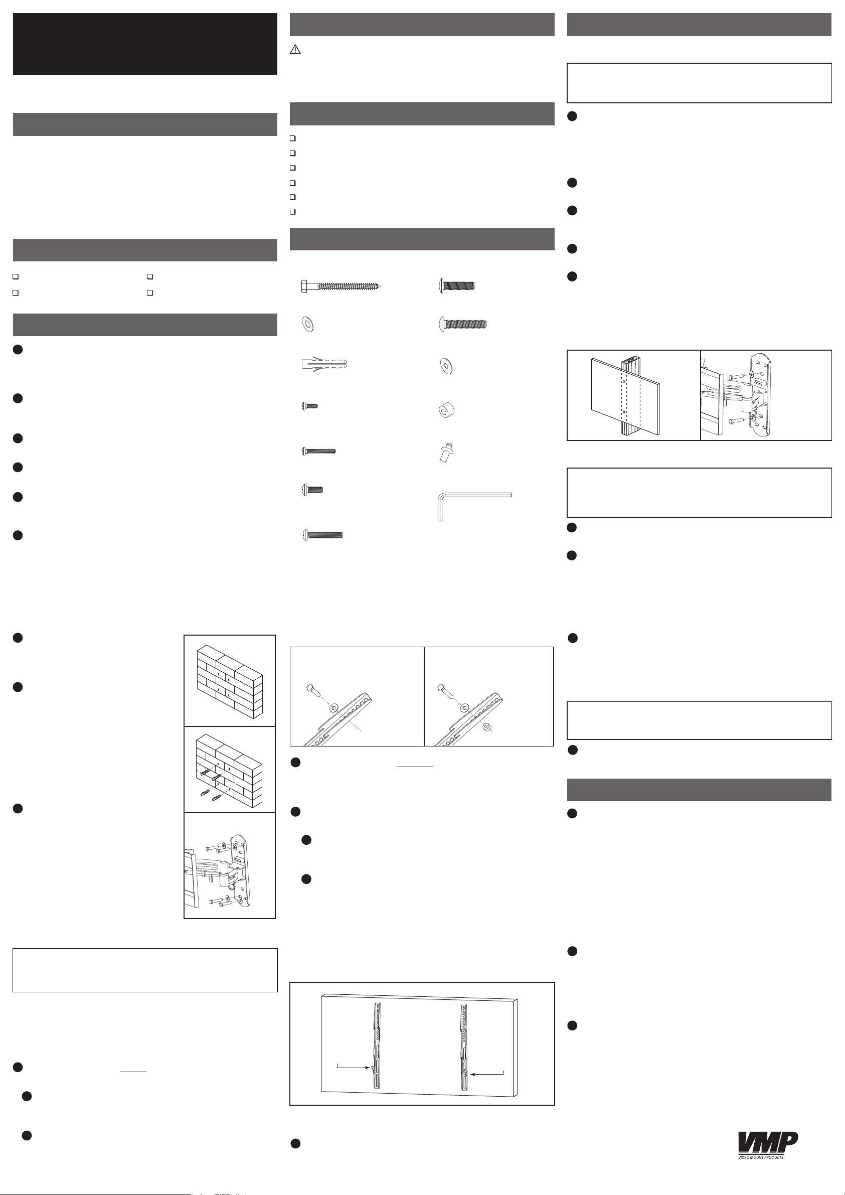
Part 2 – Attaching the Mount Arms to the Display
IMPORTANT! Use extra care during this part of the installation. If
possible, avoid placing your display facedown as it may damage
the viewing surface.
NOTE: This mount comes with a selection of dierent screw
diameters and lengths to accommodate a wide variety of
display models. Not all of the hardware in the kit will be used. If
you cannot nd the appropriate screw size in the kit provided,
consult the manufacturer of your display for more information.
1
Determine the correct length of screw to use by examining
the back of your display:
A
If the back of your display is at and the mounting holes
are ush with the surface, you will use the shorter screws
(D, F or H) from the hardware kit.
B
If the back of your display is curved, has a protrusion, or if
the mounting holes are recessed, you will need to use the
longer screws (E, G or I) and may also need to use the
spacers (K).
Part 2 – Attaching the Mount Arms to the Display
(continued)
For displays with
at backs.
2
Determine the correct diameter of screw to use by carefully
trying one of each size (M4, M6 and M8) from the hardware
kit. Do not force any of the screws – if you feel resistance
stop immediately and try a smaller diameter screw.
3
Attach the mount arms to the back of your display using
the screws identied in steps 1 and 2 (see Fig. 6):
A
If you are using the M4 or M6 screws you will also need
to use the M6 washers (J). M8 screws do not require
washers.
B
If you are using the longer screws on a display with a
curved or recessed back, you may also need to use the
spacers (K). Use one spacer or two spacers stacked as
needed.
Only use a spacer if necessary.
NOTE: The mount arms must be attached with the safety
tabs facing outward (i.e. away from the middle of the
display) (see Fig. 7). Otherwise, the safety tabs cannot be
easily accessed.
Safety Tab
For displays with curved
or recessed backs.
Safety Tab
Fig. 6
Fig. 7
Part 3 – Final Assembly
1
With the help of another person, carefully lift your
display and place it on the mount.
display until the mount arms have securely hooked onto
the mount.
Do not release the
Part 3 – Final Assembly (continued)
2
Move the safety tab located on each arm into position
so that it prevents the display from being lifted from the
mount. Insert a safety stopper (L) into each tab to keep it
in place. A padlock (not included) can be used in place
of one of the safety stoppers to help prevent unwanted
removal of the display.
IMPORTANT! The safety tabs and stoppers must be used at all
times to prevent the display from being accidentally knocked from
the mount.
3
Cables can be routed through the hooks located on the
mount to keep them organized and out of the way.
OPERATION AND ADJUSTMENT
1
To change the tilt angle of your display, have one person
hold the display rmly in place while another person
loosens the tilt knobs located on each side of the mount.
Once loosened, you may move your display to the desired
position. Re-tighten the tilt knobs to lock the tilt angle in
Do not release the display until the tilt knobs are
place.
fully tightened.
NOTE:
The tilt adjustment knobs have a ratchet feature. If
you need to change the position of the knob without
tightening or loosening it, simply pull the knob outward
before turning.
2
Swivel adjustments can be made by grasping the display
rmly and moving it to the desired position. Be careful that
ngers or cables do not get pinched when moving the
mount. If any of the swivel joints are too tight or too loose,
they can be adjusted using the S4 Allen key (M) from the
hardware kit.
3
Periodically clean your mount with a dry cloth. Inspect all
screws and hardware at regular intervals to ensure that no
connections have become loose over time. Re-tighten as
needed.
Phone number: 877-281-2169
 Loading...