

Page 1
Instruction Sheet For:
FP-MFTB
For more information, please contact us at:
345 Log Canoe Circle, Stevensville, Maryland 21666
Toll Free: 877.281.2169 Phone: 410.643.6390 Fax: 410.643.6615
www.videomount.com
Page 2
8
15
5
11
17
14
9
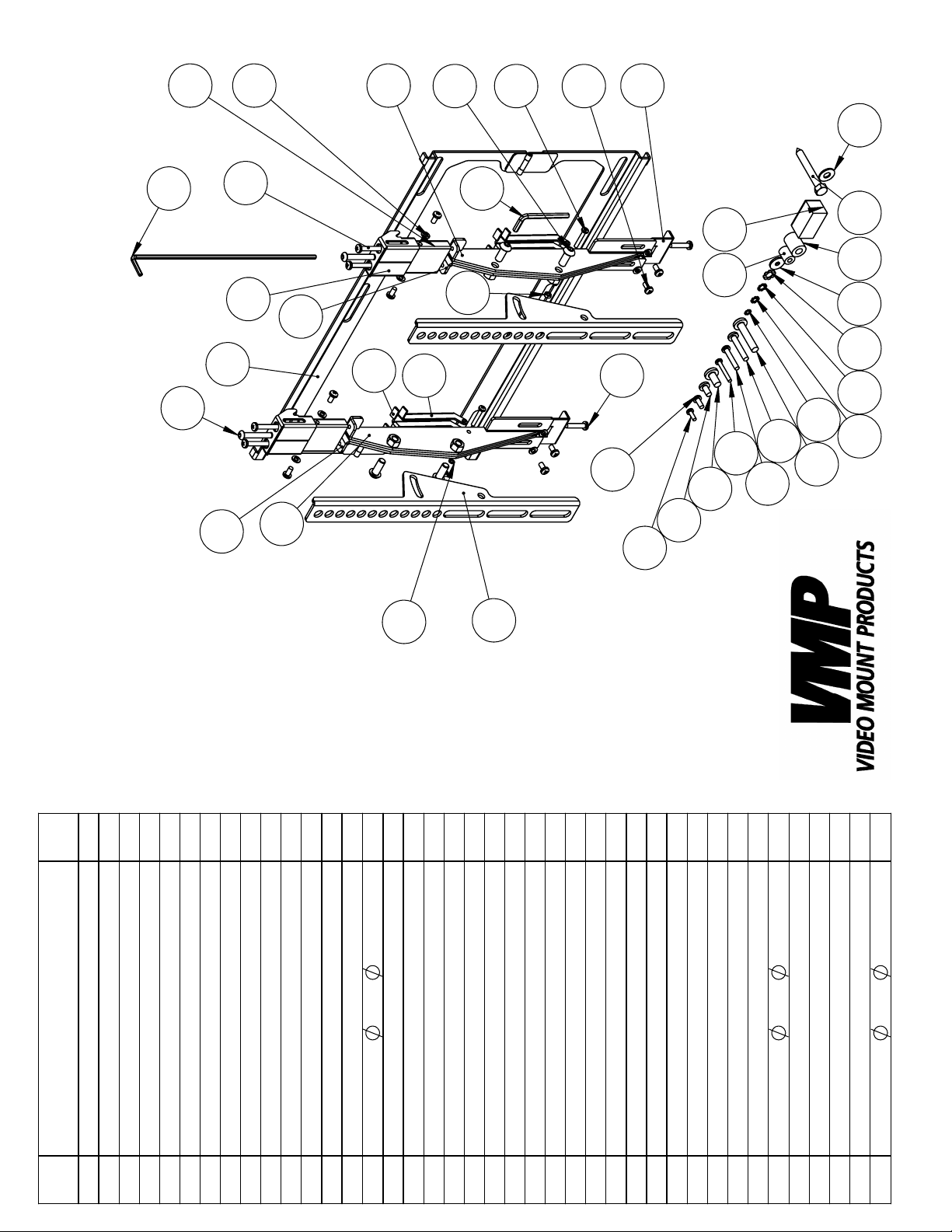
FP-MFTB
21
12
13
7
4
1
2
3
20
10
18
19
22
38
37
36
35
3432
16
33 39 40
31
29
27
24
26
25
23
6
28
30
1
1
1
Qty
Wall Plate
DESCRIPTION
1
NO.
ITEM
1
Side Wall B
Side Wall A
Side Wall C
2
3
4
1
2
2
2
2
Leveler
Top Hook
Tilt Bracket
Side Wall D
Securement Bracket
5
6
7
8
9
8
2
2
2
2
4
2
4
2
4
8
10*T1.0
5.3*
Kick Stand
Screw M5*P0.8*L25
Screw M5*P0.8*L60
Screw M5*P0.8*L10
Socket Screw M6*P1.0*L40
Socket Screw M8*P1.25*L20
10
11
12
13
14
Screw M4*P0.7*L25
Washer
15
Spring Lock Washer M4
16
17
18
1
Pad
Hex Nut M4*P0.7
Long Allen Key M4
19
20
21
1
4
4
4
4
4
4
4
M5 Allen Key
Screw M4*P0.7*L12
Screw M5*P0.8*L12
Screw M6*P1.0*L12
Screw M4*P0.7*L30
Screw M5*P0.8*L30
Screw M6*P1.0*L35
27
28
29
22
23
Screw M8*P1.25*L16.5
24
25
26
4
4
4
1
4
4
4
4
4
18*T2.0
5.5*
Spacer M6
Lock Washer M4
Lock Washer M5
Lock Washer M6
Lock Washer M8
Screw M8*P1.25*L40
Washer
30
31
32
33
34
35
36
4
Spacer M8
Magnetic Level
Lag Screw 5/16"*L2.5"
37
38
39
4
19*T1.6
8.3*
Washer
40
Page 3

Step 2: Starting adjustments
Step 3: Attaching the wall plate to
the wall
Step 1
Lay out all parts to your mount and match them to the parts list
provided. Verify that you have all your parts before attempting to
assemble the mount.
Step 2
Before starting, make sure to tighten the socket screw at the top of
the tilt brackets as far as it will go to raise the brackets to the
maximum height. Also take this time to make sure the screws )
on the side of the top hook and the screws that attach
the securement bracket are just loose enough to slide freely
12
14
7
14
9
in their respective slots.
Step 3
Mark the wall or desired mounting surface in preparation of installation of wall plate . If mounting to wooden studs, pre drill
pilot holes using a 7/32” drill bit. Attach the wall plate to the
wooden stud using the 5/16” by 2.5” long lag screw and
washer (#40) making sure the folded tabs on the wall plate as-
40
1
1
39
sembly are towards the top. WARNING: Please verify that your
mounting surface will support the combined weight of your mount,
mounting hardware, and at panel. Also verify that the mounting
surface is safe to drill through. Please note only mounting hardware for mounting to wooden studs will be provided with the unit.
If mounting to a surface other than wooden studs then other hard-
ware will be required. If in doubt or uncertain about any of the
above, please contact a professional installer.
Step 4A: Attaching the at panel to
the tilt brackets (spacers not needed)
Step 4B: Attaching the at panel to
the tilt brackets (spacers used due
to recessed hole pattern)
Step 4
Determine the correct screw size and if you need to use washers,
lock washers, or spacers. Note: Spacers are used for TVs with re-
cessed hole patterns. Secure the display to the tilt brackets (#6)
using the appropriate hardware (#23 through #37). Note: The
23
37
6
brackets have to be level with each other to work properly. Note:
The socket screws (#11) on each bracket should be pointed to-
11
wards the outside of the at panel when attached to allow adjustment of the tilt tension post installation.
Page 4

Step 5: Securing the mounting
brackets
Step 6: Engaging the securement
brackets
Step 5
To wire the at panel, pull the bottom of the at panel up
and lower the kick stand (#10on both tilt brackets. Attach
any cables and wires at this time to the at panel display.
When nished fold the kick stand (#10back up against the
tilt brackets to lower the at panel back to the wall plate
Step 6
Check the securement brackets (#9) and make sure the
bottom lip of the wall plate (#1) is between the two metal
anges on the securement brackets. If not adjust the securement brackets (#9) until this is true. Tighten the screw
(#16) in the bottom of the securement bracket (#9) until
16
the bracket is pressed rmly against the bottom lip of the
wall plate (#1). This step secures the tilt brackets to the wall
plate (#1).
Step 7
To adjust the vertical height of the unit unscrew the socket
screw (#12) at the top of the tilt brackets. To adjust the roll
of the unit for leveling purposes simply unscrew the same
screw (#12) on the side which you wish to lower until you
have achieved the desired height. Note: The further out of
level the two tilt brackets are the harder it will be to adjust
the higher side. If you nd it difcult to turn the higher side,
simply press up on the at panel on the higher side to relieve
the pressure to allow you to turn the screw easier.
1
1
12
12
9
10
10
.
1
9
1
9
Step 7: Adjusting the height or roll of
the at panel
Step 8: Adjusting the tilt tension
on the tilt brackets
Step 8
To adjust the tilt tension of the of the tilt brackets loosen or
tighten the socket screws (#11) on the side of the tilt brackets until you have achieved desire tension.
Please verify that all nuts and screws are securely tightened.
11
Enjoy Your Mount!
WARNING: The installer of these products must verify that
the mount surface, ceiling or wall, will safely support the
combined weight of all attached equipment and hard-
ware. Video Mount Products will not be held liable for the
improper use or installation of its products.
 Loading...