

Page 1
Instruction Sheet For:
FP-LFV & FP-LFVB
For more information, please contact us at:
345 Log Canoe Circle, Stevensville, Maryland 21666
Toll Free: 877.281.2169 Phone: 410.643.6390 Fax: 410.643.6615
www.videomount.com
Page 2
1
6
3
24
23201918171615
FP-LFV
2
2
2
2
6
2
1
4
QTY.
22
10
9
4
4
4
4
4
4
5
4
4
7 8
11
12
13
4
4
4
1
6
4
4
4
4
6
21
14
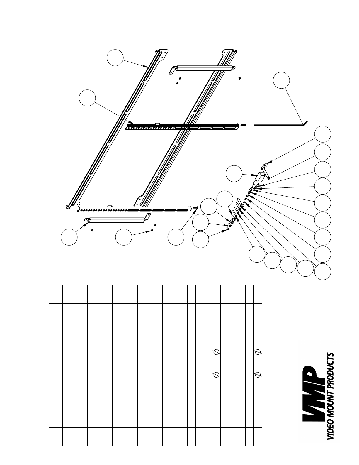
Wall Plate
DESCRIPTION
ITEM
Vertical Support
Cross Screw M4*P0.7*L5
Screen Mounting Bracket
1
2
3
NO.
4
Lock Washer M4
Long Allen Key M4
Cross Screw M4*P0.7*L12
Cross Screw M5*P0.8*L12
Cross Screw M6*P1.0*L12
Cross Screw M4*P0.7*L30
Cross Screw M5*P0.8*L30
Security Screw M5*P0.8*L20
5
6
7
Cross Screw M8*P1.25*L16
8
9
10
Cross Screw M6*P1.0*L35
11
12
13
Lock Washer M5
Cross Screw M8*P1.25*L40
14
15
16
18*T2.0
5.5*
Spacer M5
Spacer M8
Lock Washer M6
Lock Washer M8
Washer
17
18
19
Magnetic Level
Lag Screw 5/16"*2.5"
20
21
22
23
19*T1.6
8.3*
Washer
24
Page 3

Step 2: Assembling the wall plate
Step 1
Before starting, lay out all parts to your mount and match them to
the parts list provided. Verify that you have all your parts before
attempting to assemble the mount.
Step 2
Assemble the wall plate by attaching the two horizontal wall plates
using the vertical supports and short M4 screws . You can
1
2
4
identify the difference between the top and bottom rail by the
fact that the top rail is the one with the stopper fl aps on either end.
Step 3
Mark the wall or desired mounting surface in preparation of installation of wall plate assembly and . If mounting to wooden
1
2
studs, pre drill pilot holes using a 7/32” drill bit. Attach the wall
23
2
24
plate assembly and to the wooden stud using the 5/16” by
1
2.5” long lag screw and washer making sure the folded
tabs on the wall plate assembly are towards the top. WARNING:
Please verify that your mounting surface will support the combined
weight of your mount, mounting hardware, and fl at panel. Also
verify that the mounting surface is safe to drill through. Please note
only mounting hardware for mounting to wooden studs will be provided with the unit. If mounting to a surface other than wooden
studs then other hardware will be required. If in doubt or uncertain
about any of the above, please contact a professional installer.
Step 4
Determine the correct screw size and if you need to use washers,
lock washers, or spacers. Note: Spacers are used for TVs with re-
Step 3: Mounting the wall plate
cessed hole patterns. Secure the TV to the mounting rails using
the appropriate hardware through . Note: The brackets
have to be level with each other to work properly.
Step 4A: Attaching the mounting brackets to the
fl at panel (spacers not needed)
3
7
Step 4B: Attaching the mounting brackets to
the fl at panel (spacers needed)
21
Page 4

Step 5: Securing the mounting brackets
Step 5
Use the hooks in the mounting rails to hook on the top rail
of the wall plate assembly . Use security screws and
the long allen key to secure the TVs to the bottom rail
and to secure its horizontal position.
1
Please verify that all nuts and screws are securely tightened.
5
1
3
6
Enjoy Your Mount!
WARNING: The installer of these products must verify that the mount surface, ceiling or wall, will safely
support the combined weight of all attached equipment and hardware. Video Mount Products will not
be held liable for the improper use or installation of its products.
 Loading...