

Page 1
Instruction Sheet For:
FP-LDSB
For more information, please contact us at:
345 Log Canoe Circle, Stevensville, Maryland 21666
Toll Free: 877.281.2169 Phone: 410.643.6390 Fax: 410.643.6615
www.videomount.com
Page 2
17
5
9
11
2
15
1
FP-LDSB
7
3
14
11
4
13
36
7
19
35
33
8
16
6
29
22
27
20
21
23
26
28
25
24
34
32
31
30
18
3
3
2
2
2
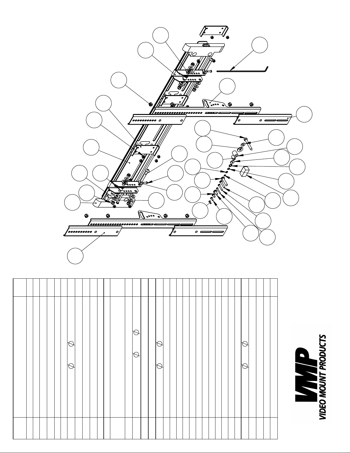
QTY.
Tilt Plate
End Cap
Wall Plate
DESCRIPTION
Connector Plate
Screen Mounting Bracket
12
2
2
Cross Screw M6*P1.0*L60
1
2
2
6+6
19*T1.6
8.3*
Washer
14
Long Allen Key M4
Nylon Nut M8*P1.25
Security Screw M5*P0.8*L20
4
Extension B
Extension A
Square Neck Screw
4
4
16
20*T2.0
8.5*
M8*P1.25*L20
Tilt Bushing
Nylon Nut M6*P1.0
Nylon Washer
2
4
4
4
4
4
1
20*T2.0
8.5*
Magnetic Level
Screw M4*P0.7*L12
Screw M5*P0.8*L12
Screw M6*P1.0*L12
Washer
4
Screw M4*P0.7*L30
Screw M5*P0.8*L30
Screw M8*P1.25*L16
4
4
4
4
4
Lock Washer M4
Lock Washer M5
Screw M6*P1.0*L35
Screw M8*P1.25*L40
Lock Washer M6
4
4
4
4+2
18*T2.0
5.5*
Lock Washer M8
Washer
2
Spacer M5
Spacer M8
Cross Screw M8*P1.25*L65
6
Lag Screw 5/16"*L2.5"
NO.
ITEM
1
2
3
4
5
8
6
9
7
11
12
13
14
15
16
17
18
19
20
21
22
23
24
25
26
27
28
29
30
31
32
33
34
35
36
Page 3

Step 2: Connect the wall plates
together
Step 3: Mounting the wall plates
Step 1
Before starting, lay out all parts to your mount and match them to the
parts list provided. Verify that you have all your parts before attempting to assemble the mount.
Step 2
Connect the desired amount of wall plates together using the
connector plates and nylon nuts .
2
15
1
Step 3
Mark the wall or desired mounting surface in preparation of installation of wall plate
using a 7/32” drill bit. Attach the wall plate
using the 5/16” by 2.5” long lag screw
ing sure the small ear fl aps are on the top rail of the wall plate
(#1). If mounting to wooden studs, pre drill pilot holes
1
(#1) to the wooden stud
1
36
(#36) and washer (#7) mak-
7
1
(#1).
WARNING: Please verify that your mounting surface will support the
combined weight of your mount, mounting hardware, and fl at panel.
Also verify that the mounting surface is safe to drill through. Please
note only mounting hardware for mounting to wooden studs will be
provided with the unit. If mounting to a surface other than wooden
studs then other hardware will be required. If in doubt or uncertain
about any of the above, please contact a professional installer.
Step 4: Attaching the end caps
Step 4
Attach the end caps to the ends of the wall plates using the
nylon nuts .
15
3
1
Step 5
If you need to extend the rails for mounting the fl at panel display in
portrait then proceed with the following step. Otherwise proceed to
the next step.
Attach extension A and extension B using the nylon nuts .
12
13
11
Step 5: Attaching the extensions
Page 4

Step 6: Locking the tilt in place
Step 7A: Attaching the mount-
ing brackets to the monitor
(spacers not needed)
Step 6
If you wish to specify a tilt angle for the tilt brackets then proceed
with the following step. Otherwise proceed to the next step.
The tilt is lockable at 0°, 5°, 10° and 15°. The way you do this is for
0° line up the hole closest to the tilt arc on the screen mounting
bracket with the hole closest to the top square in the tilt plate
. Then insert the M6 screw through both the tilt plate and
5
the screen mounting bracket and use the nylon nut to lock
4
6
4
5
15
the tilt in place. For 5 degrees do the same, but with the next set of
holes down and so on for 10 and 15 degrees.
Step 7
Determine the correct screw size and if you need to use washers, lock
washers, or spacers. Note: Spacers are used for TVs with recessed
hole patterns. Secure the TV to the screen mounting bracket
4
using the appropriate hardware ( through ). Note: The
20
34
brackets have to be level with each other to work properly.
Step 8
Hook the tilt plate onto the wall plates . Note: Make sure that
the wall plate that the tilt plate is hooked onto is secured into
5
1
5
the mounting surface. To secure the tilt plate to the wall plate
1
, tighten security screws in the threaded hole in the bottom
of the tilt plate using the long allen key . This will also secure
5
8
1
5
9
your horizontal positioning for the fl at panel.
Step 7B: Attaching the
mounting brackets to the
monitor (spacers used due to
recessed hole patterns)
Step 8: Securing the mounting
brackets to the wall plate
Step 9
To adjust the tension in the tilt mechanism to the desired level,
tighten/loosen the nylon nuts on the tilt arc.
11
Please verify that all nuts and screws are securely tightened.
Enjoy Your Mount!
WARNING: The installer of these products must verify that the
mount surface, ceiling or wall, will safely support the combined weight of all attached equipment and hardware. Video Mount Products will not be held liable for the improper use
or installation of its products
 Loading...