

Page 1
VIDEO MOUNT PRODUCTS
For more information, please contact us at:
345 Log Canoe Circle, Stevensville, Maryland 21666
Toll Free: 877.281.2169 Phone: 410.643.6390 Fax: 410.643.6615
www.videomount.com
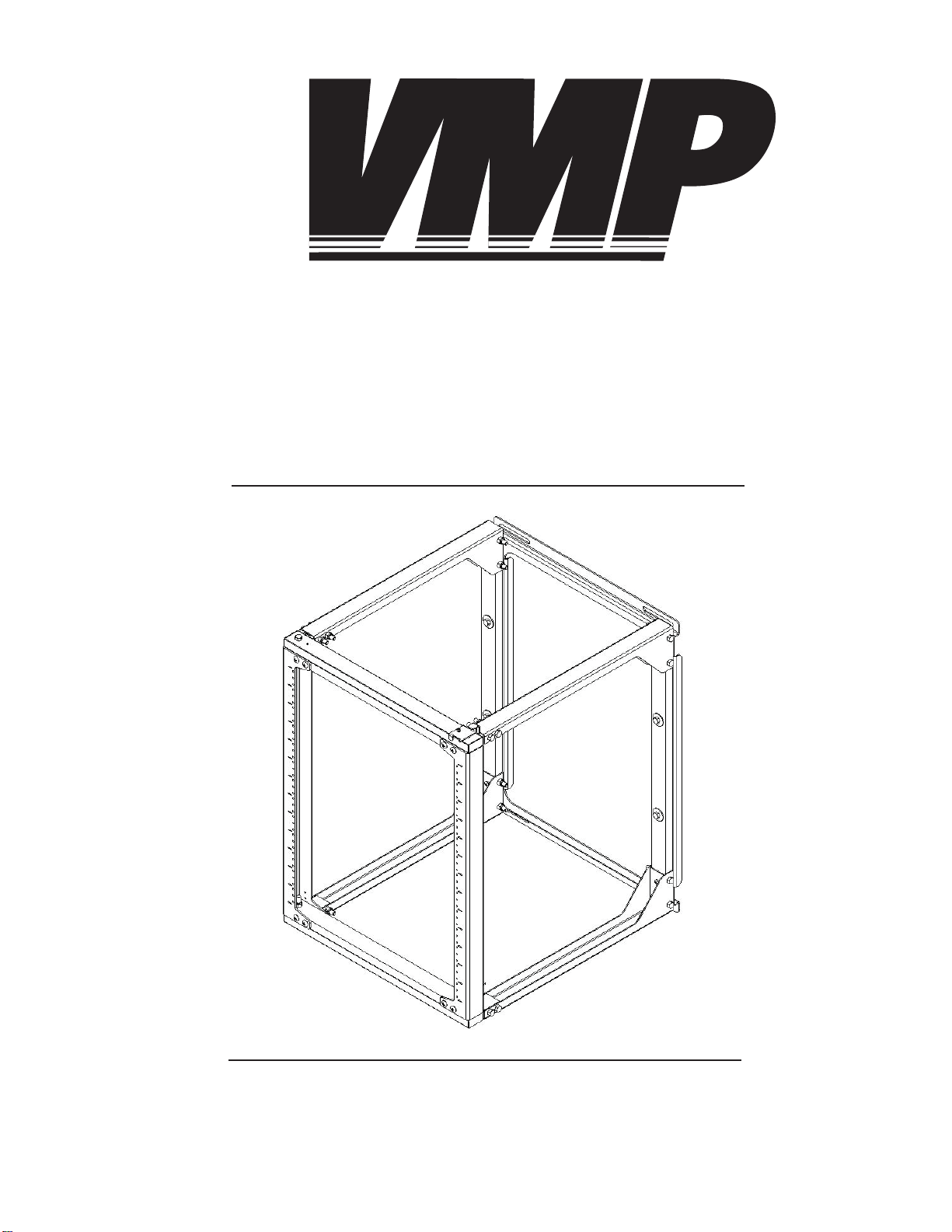
Instruction Sheet For:
ER-W24
Page 2
2
2
2
4
1
8
8
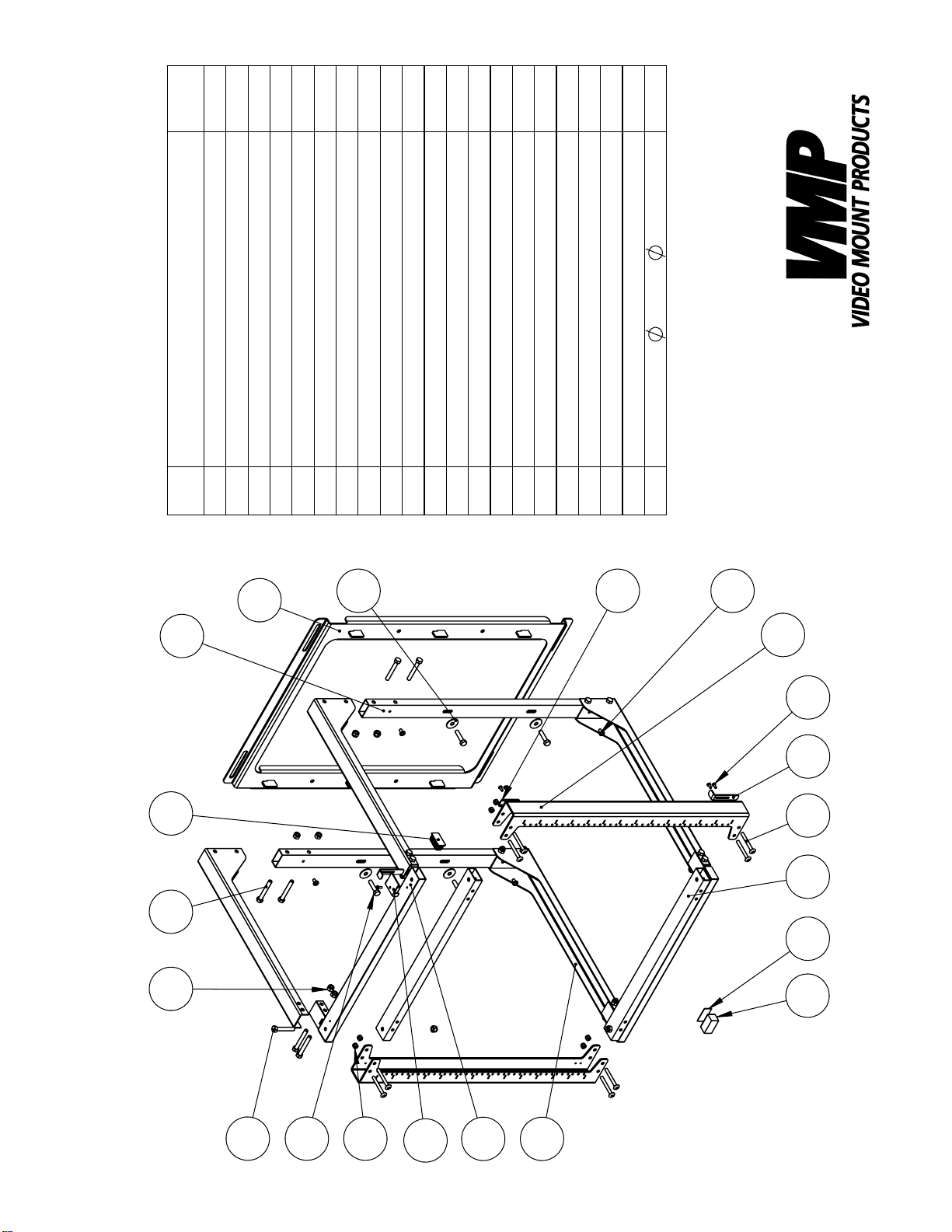
QTY.
Rack Rail
Support Bar
DESCRIPTION
Wall Plate
Vertical Supports
Wall Arm Support
ER-W24
1
2
4
5
NO.
ITEM
6
18
Nylon Nut 1/4" - 20UNC
Nylon Nut 5/16" - 18UNC
Screw 1/4" - 20UNC*L2.25"
10
12
13
2
5
2
4
1
1
2
1
1
4
4
16
End Plug
Slide Lock
Screw M4*P0.7*L10
Hex Screw 5/16" - 18UNC*2"
15
17
18
Top Stop
Top Catch
Horizontal Support
19
22
23
25
Magnetic Pad
Magnetic Level
Screw M6*P1.0*L10
Hex Screw 5/16" - 18UNC*L2.5"
Hex Screw 5/16" - 18UNC*L35mm
26
27
28
29
30
4
29*T1.6
5/16"*
Washer
31
19
28
13
6
4
31
22
29
2
171810
25
27
26
15
30
12
23
1
5
Page 3
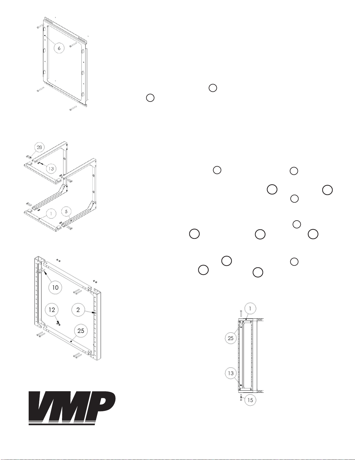
Step1
Before starting, lay out all parts to your mount and match them to
the parts list provided. Verify that you have all your parts before attempting to assemble the mount.
Step 2
Mark the wall or desired mounting surface in preparation of installation
of wall mounting plate . Pre-drill if necessary and mount wall plate
to desired surface.
6
6
Step 2: Mounting the wall plate
(Lag screws are not included)
Step 3: Attaching the support bars
Warning: Please verify that your mounting surface will support the
combined weight of your equipment, equipment rack and mounting
hardware. Also verify that the mounting surface is safe to drill through.
If in doubt, please contact a professional installer.
Step 3
Attach the support bars to the wall arm supports making sure
the threaded holes in the support bars are point out from the center
of the rack. Use the 2.25” long 5/16” screws and nylon nuts )
to attach the support bars to the wall arm supports .
1
28
5
13
5
Step 4
Create the rack rail frame by attaching the rack rails to the horizontal supports using the ¼” screws and nylon nuts .
25
10
2
12
Step 5
Attach the rack rail frame to the support bars using the 2”
long 5/16” screws and nylon nuts .
15
25
1
13
Step 4: Creating the rack rail frame
VIDEO MOUNT PRODUCTS
Step 5: Attaching the rack rail
frame to the support bars
Page 4
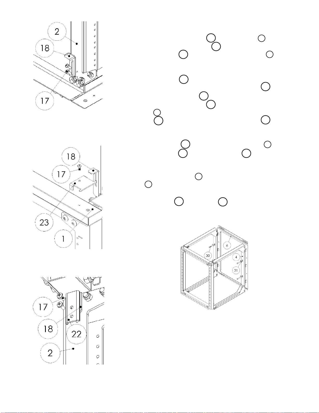
Step 6 : Attaching the bottom
slide lock
Step 6
Attach the bottom slide lock to the rack rail opposite the
pivot point using the M4 screws . To lock the bottom lock simply
slide the slide lock into the slot in the support bar .
18
18
2
17
1
Step 7
Take the top stop and point it so the side with the downward
ears is closest to the pivot point. Take the slide lock and place
the fl at ear on the top stop closest to the wall into the slot in the
slide lock. Slide the slide lock into the slot cut into the top support bar on the side opposite of the pivot point and secure the
top stop to the support bar using the M4 screw .
1
23
23
18
23
18
17
Step 8
Take the top catch and attach it to the rack rail on the side
with the slide lock using the M4 screws .
22
18 17
2
Step 9
Lift the vertical supports onto the tabs coming out of the wall
6
plate . Pull the vertical supports down onto the tabs as far as possible. Secure the vertical supports to the wall plate using the short
5/16” hex screws and washers .
30
4
31
Step 7: Attaching the top slide lock
Step 8: Attaching the top catch
Please verify that all nuts and screws are securely tightend.
Step 9: Attaching the vertical sup-
ports to the wall plate
Enjoy Your Mount!
WARNING: The installer of these products must verify that the mount-
ing surface, ceiling or wall, will safely support the combined weight
of all attached equipment and hardware. Video Mount roducts will
not be held liable for the improper use or installation of its products.
 Loading...