

Page 1
Instruction Sheet For:
ERVWC-5U20 / ERVWC-5U36
5U Vertical Wall Mount Rack Instruction Manual
For more information, please contact us at:
345 Log Canoe Circle, Stevensville, Maryland 21666
Toll Free: 877.281.2169 Phone: 410.643.6390 Fax: 410.643.6615
www.videomount.com
tech@videomount.com
Page 2
2
1
6
5
(Adjustable)
3
4
11
1
1
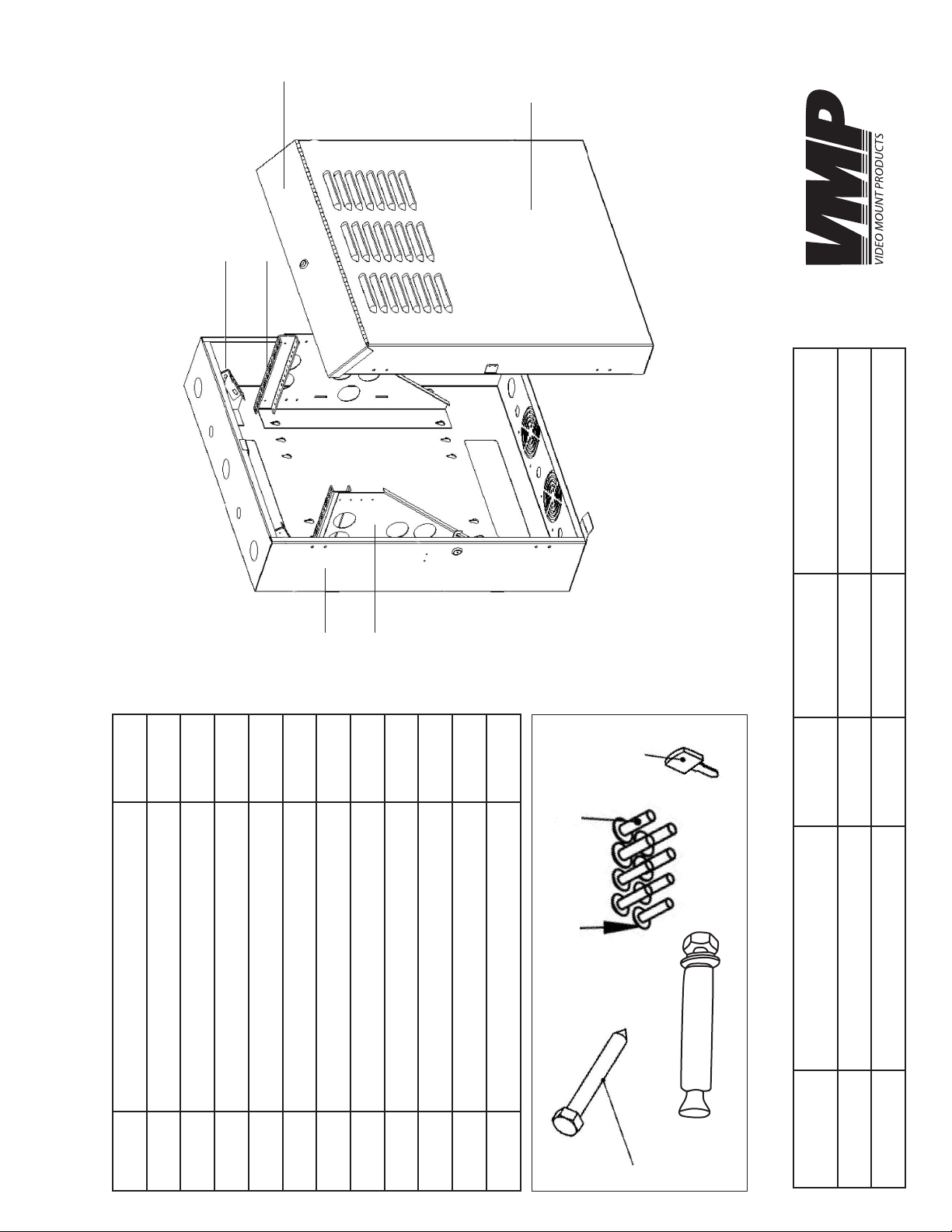
45 lbs 150 lbs 17” to 20”
10
55 lbs 150 lbs 33” to 36”
9
8
Part No. Part Name Quantity
1 Front Door
** ERVWC-5U20/ERVWC-5U36 **
2 Top Panel Door
3 Rear Cabinet Panel14 Vertical Mounting Bracket25 Vertical Mounting Rails 2
6 Patch Panel Mounting Bracket 2
7 Lag Screw - 6M x L70mm 4
8 Wall Anchor 4
9 M6 * 1/2” Screw 12
10 12-24 * 5/8” Rack Screw 12
11 Cabinet Keys 2
7
Model No. Dimensions (HxWxD) Unit Weight Load Capacity Mounting Depth
SPECIFICATIONS
ERVWC-5U20 28.8” x 25.6” x 9.75”
ERVWC-5U36 42.75” x 25.6” x 9.75”
2
Page 3

Safety First
- These enclosures are heavy and you should always have at least 2 people involved with moving,
unpacking and mounting them.
- Please verify that your mounting surface will safely support the combined weight of the enclosure,
mountinghardwareandequipmentinstalledinthecabinet.Conrmthatthemountingsurfaceis
safe to drill through. Please note that only mounting hardware for mounting to wooden studs is
provided with the unit. If mounting to a surface other than wooden studs, then other hardware
will be required. This product should be installed by professionals or professionally installed.
*Video Mount Products will not be held liable for the improper use or installation of their products.*
- You are working with equipment that requires proper ventilation. Do not block or cover external
ventilation openings or, if you are using fans, the fan intake area at the bottom of the enclosure.
- Keep the enclosure and the related equipment in a clean dry area for best results.
Get Familiar
- Take a few minutes to familiarize yourself with your enclosure as you unpack it, and also spend
some time planning for your mounting location, as well as how you are going to populate your
equipment into the enclosure. While the enclosure ships fully assembled, you still have the option
of reversing the door and adjusting the vertical mounting brackets. Consider making whatever
adjustments to the door and the vertical rails that you need to, before installing the enclosure on
the wall.
LATCH
LOCK
HINGE
HINGE
HINGE
HINGE
LATCH
LOCK
Section 1 - Reversing the Front Door
You will encounter a wide variety of installation applications
and it may be necessary from time to time to have to reverse
the swing direction of the door. The front door can be
reversed by switching the conguration of the hinges, latch
and lock from one side to the other. Simply remove the
hinges, latch and lock from one side and move all of the
pieces to the corresponding holes on the opposite side. You
will have the 2 hinges on one side (1 – Top and 1 – Bottom)
and the latch and lock on the other side.
Note: You will nd that the unused screw holes are lled
with a small rubber ll plug. These plugs are easily removed.
Please retain them and replace them into the unused holes
on the opposite side.
3
Page 4

Section 2 - Vertical Mounting Rails
Your enclosure provides 2 threading options based upon your
preference and the equipment you are using. One side of the rail
is threaded for M6 hardware and the other side is threaded for 12-
24. The rails are visibly labeled with both options. Position the rails
with the desired thread pattern on top. To install your equipment,
use the included M6 or 12-24 hardware, or the hardware provided
with your equipment to secure equipment to the rails.
Section 3 - Adjusting the Mounting Rail Depth
Note: Do not use the mounting rails without both screws installed
and attached to the vertical mounting bracket. Do not adjust
the rails while equipment is installed in the enclosure.
The two horizontal mounting rails are factory-installed with a
mounting depth of 20” for ERVWC-5U20 and 36” for ERVWC-5U36
The rails can be adjusted in 1-inch increments for mounting
depths between 17-20 inches for ER-VWC5U20 and 33-36 inches
for ER-VWC5U36. It is not necessary to adjust the mounting rails
unless your equipment requires a different mounting depth.
.
To adjust the height of the rails, simply remove the 2 screws,
position the rails vertically to the desired depth and reattach
using the 2 screws. Make sure to adjust both rails equally.
Section 4 - Mounting your Enclosure
The alignment of the keyhole cutouts in the back of the cabinet
provides multiple mounting options for your convenience. There
are 4 sets of 5 keyholes, which allows for 5 mounting options on
16” center. Each set of keyholes are spaced in 2” intervals.
For optimal results, use a level and measure to position your
mounting areas precisely. Always use appropriate mounting
hardware to secure the enclosure to the wall.
Please verify that your mounting surface will safely support the
combined weight of the enclosure, mounting hardware and
equipmentinstalledinthecabinet.Conrmthatthemounting
surface is safe to drill through. Please note that only mounting
hardware for mounting to wooden studs is provided with the unit.
If mounting to a surface other than wooden studs, then other
hardware will be required. This product should be installed by
professionals or professionally installed. *Video Mount Products
will not be held liable for the improper use or installation of their
products.*
4
Page 5

Section 5 - Installing your Equipment
NOTE: The enclosure must be mounted and stabilized prior to installing your equipment. If you are using
sliding equipment rails, be careful when extending the rails. Do not extend more than one set of sliding
equipment rails at one time. Avoid extending sliding equipment rails near the top of the enclosure.
Each rack unit is marked on the rail for your convenience. To install your equipment, lower it into the
enclosure and set it on the mounting rails. Line up the mounting holes on the equipment with the
mounting holes on the mounting rails making sure to stay aligned in the rail markings. Using the
included hardware or the compatible hardware included with your component, secure your
equipment to the rack rails.
Section 6 - Patch Panel Installation (Optional)
Your enclosure also comes with an integrated, slide-out patch
panel mounting bracket. These brackets are located at the top
of the enclosure, above the vertical mounting rails and allows for
the convenient installation of a patch panel to the enclosure. For
added accessibility, the brackets partially slide out to provide
easier cable access.
To install a patch panel on the patch panel mounting bracket, use
the included mounting screws or compatible hardware provided
with your equipment, to secure your equipment to the rack rail.
Please verify that your mounting surface will safely support the
combined weight of the enclosure, mounting hardware and
equipment installed in the cabinet. Conrm that the mounting
surface is safe to drill through. Please note that only mounting
hardware for mounting to wooden studs is provided with the unit.
If mounting to a surface other than wooden studs, then other
hardware will be required. This product should be installed by
professionals or professionally installed.
*Video Mount Products will not be held liable for the improper use
or installation of their products.*
Enjoy Your Cabinet!
5
 Loading...