

Page 1

VIDEO MOUNT PRODUCTS
For more information, please contact us at:
345 Log Canoe Circle, Stevensville, Maryland 21666
Toll Free: 877.281.2169 Phone: 410.643.6390 Fax: 410.643.6615
www.videomount.com
Instruction Sheet For:
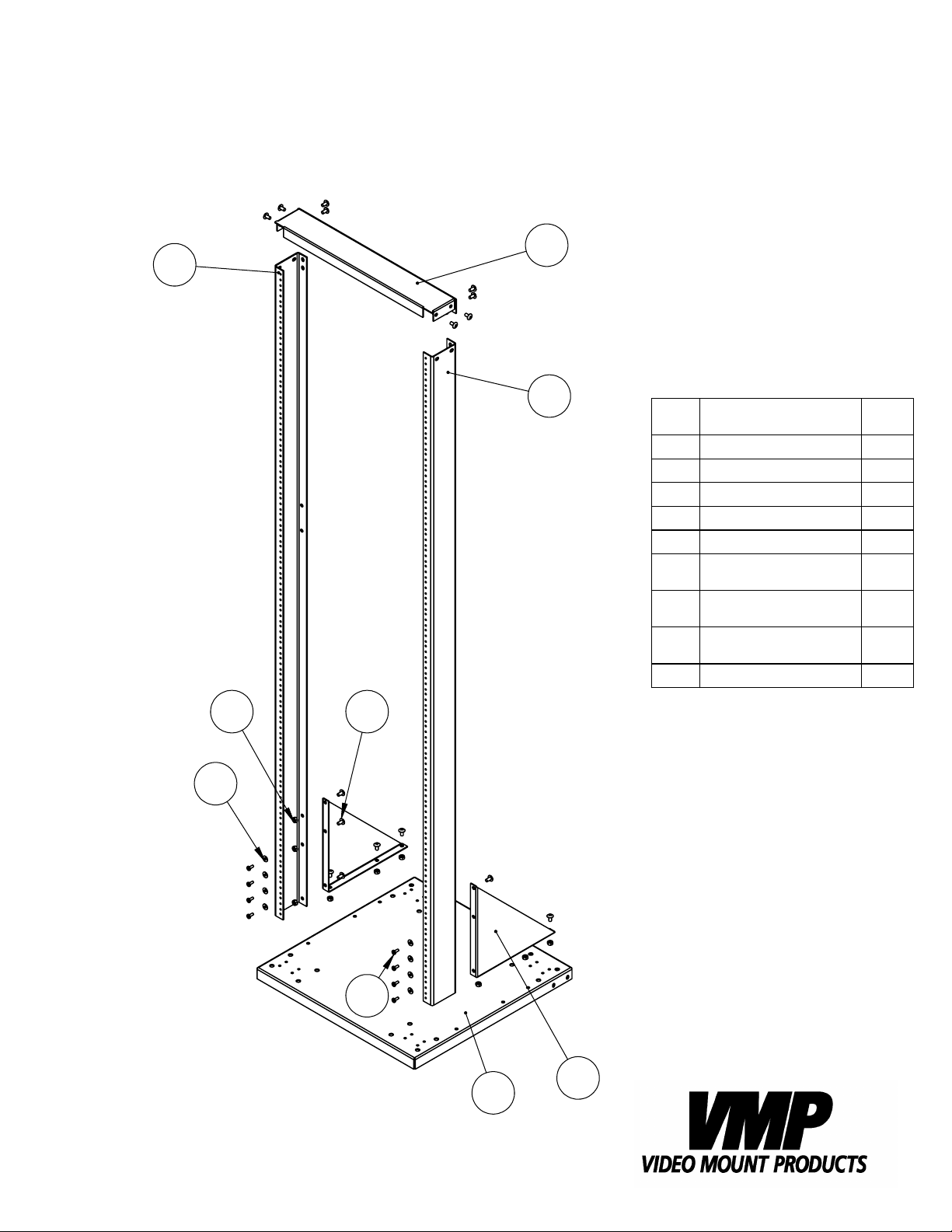
ER-1, ER-148, ER-184
Page 2
1A
ER-1
3
7 6
8
1B
ITEM
NO.
1A
1B
2
3
4
5
6
7
8
DESCRIPTION
Left Support
Right Support
Plate
Support Plate
Triangle Plate
Screw #10 -
32UNC
Screw 1/4" -
20UNC*L1/2"
Nut 1/4" -
20UNC
Plastic Washer
QTY.
1
1
1
1
2
32
20
16
32
5
2
4
Page 3

3
6
8
*** ER-148 ***
5
1B
1A
NO. Part Name QTY.
1A Left Support 1
1B Right Support 1
2 Base Plate 1
3 Top Plate 1
4 Triangle Plate 2
5 Screw 10#-32UNFx5/8" 32
6 Cross Screw 1/4"-20UNCx1/2" 16
7 Nut 1/4"-20UNC 12
8 Plastic Washer
4.6x 11.2xT0.8 32
4
6
7
2
Page 4

1A
4B
1B
7
9
6
*** ER-184 ***
NO. PART NAME QTY.
1A Left Support 1
1B Right Support 1
3 Base Plate 1
4B Top Plate 1
5 Triangle Plate 2
6 Screw 10#-32UNFx1/2'' 32
7 Cross Screw 1/4"-20UNCx1/2" 20
8 Nut 1/4"-20UNC 16
9 Plastic Washer
4.6x 11.2xT0.8 32
5
7
3
8
Page 5

Step 2: Attaching the triangle plates
Step 1
Before starting lay out all parts to your mount and match them to
the parts list provided. Verify that you have all your parts before attempting to assemble the mount.
Note: For the example images the ER-184 is shown.
Step 2
Attach the triangle plates for ER-1 and ER-148, for ER-184 to
the base plate for ER-1 and ER-148, for ER-184 using ¼” – 20
screws for ER-1 and ER-148, for ER-184 and nuts for ER-1
and ER-148, for ER-184.
6
2
8
4
3
7
5
7
Step 3
Attach the left and right supports to the triangle plates
4
for ER-1 and ER-148, for ER-184 using ¼” – 20 screws for
ER-1 and ER-148, for ER-184 and nuts for ER-1 and ER-148,
8
for ER-184.
1A
5
7
1B
6
7
Step 3 : Attaching the left and
right supports
Step 4
Attach the support plate for ER-1 and ER-148, for ER-184 to
the left and right supports using ¼” – 20 screws for ER-1
and ER-148, for ER-184 and nuts for ER-1 and ER-148, for
ER-184.
Please verify that all nuts and screws are securely tightened.
1A 1B
7
3
7
4B
6
8
Enjoy Your Mount!
WARNING: The installer of these products must verify that the mounting surface, ceiling or wall, will safely support the combined weight
of all attached equipment and hardware. Video Mount roducts will
not be held liable for the improper use or installation of its products.
Step 4 : Attaching the support plate
VIDEO MOUNT PRODUCTS
 Loading...