

Page 1

Instruction Sheet For:
DVR-MB1
For more information, please contact us at:
345 Log Canoe Circle, Stevensville, Maryland 21666
Toll Free: 877.281.2169 Phone: 410.643.6390 Fax: 410.643.6615
www.videomount.com
Page 2
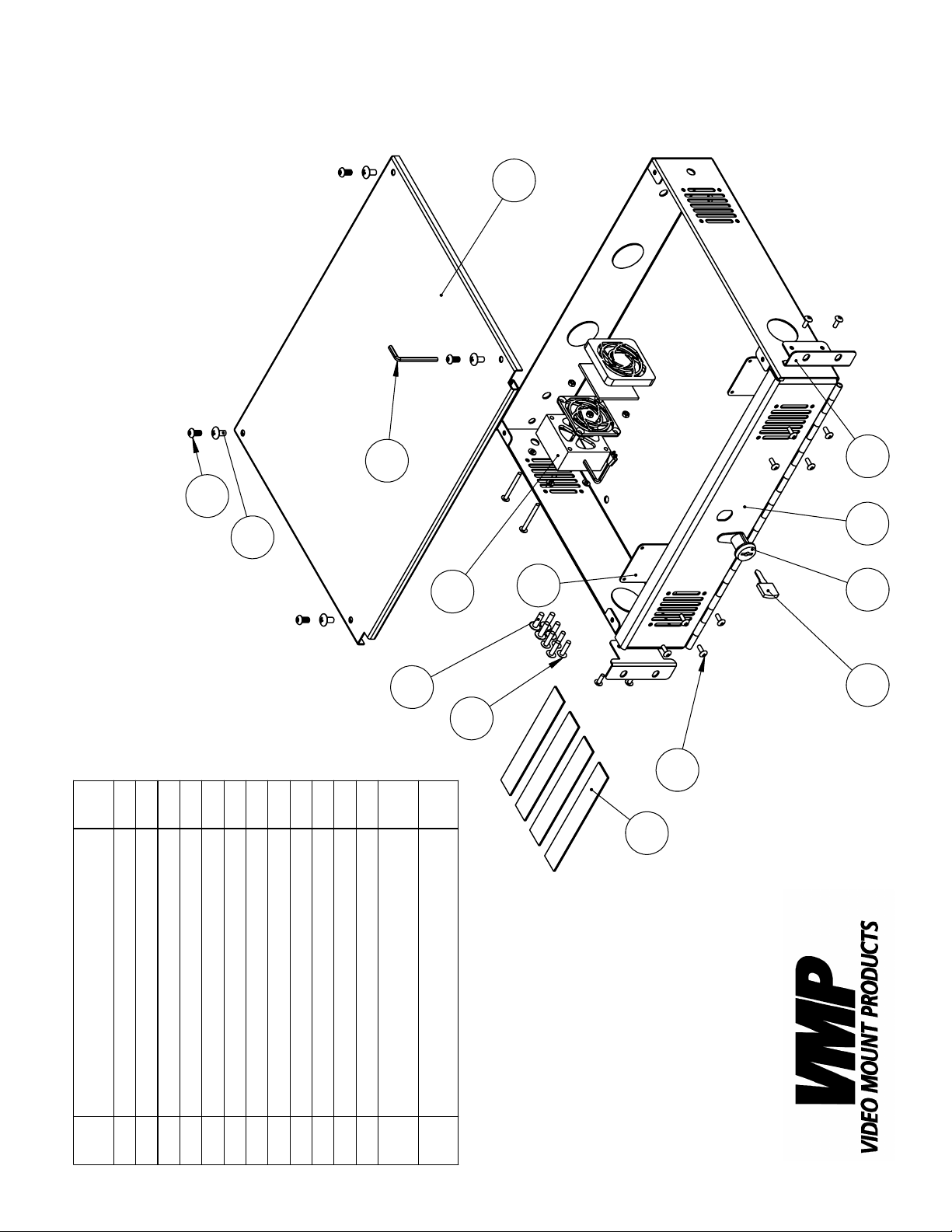
2
10
7
DVR-MB1
1
Qty
1
2
2
4
1
4
12
1
4
1
1
11
4
20
4
1
12
19
4
3
6
5
98
Top Lid
Bottom Box
DESCRIPTION
NO.
ITEM
Vent Blocker
1
2
3
Key
Velcro
Rack Mount Ear
Phillips Screw M4*P0.7*L12
4
5
6
Lock
Fan Assembly
Security Allen Key
Phillips Screw #10-
Phillips Screw M6*P1.0*L12
7
Security Screw M6*P1.0*L12
8
9
10
11
12
32UNF*L3/4"
24UNC*L3/4"
Phillips Screw #12-
19
20
Page 3
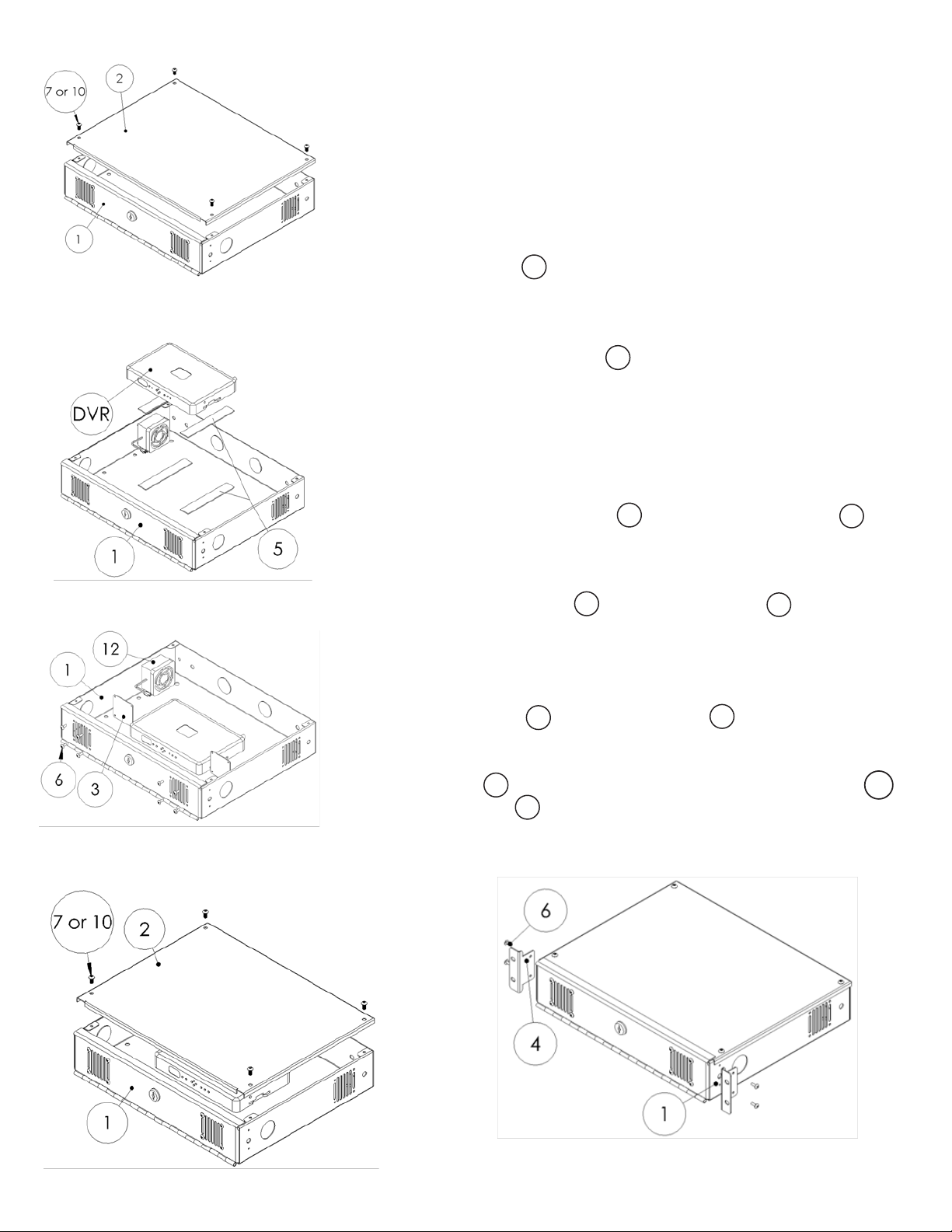
Step 2: Removing the Top Lid
Step 3: Attaching the Velcro
Step 1
Before starting, lay out all parts to your mount and match them to the
parts list provided. Verify that you have all your parts before attempting to assemble the mount.
If you are rack mounting the DVR-MB1, proceed to the next step. If
you are surface mounting the DVR-MB1 then proceed to step 8.
Step 2
Remove the Top Lid (#2) to provide better access to the inside of the
2
box.
Step 3
Apply the adhesive Velcro strip (#5) to the bottom of the DVR and to
5
the bottom of the box where you want the DVR to sit. Place the DVR
into the box making sure the Velcro attaches properly. Wire the DVR
through the knockouts as needed.
Step 4
If you wish to adjust how the air is channeled through the DVR-MB1
you can shift the Vent Blockers (#3) and/or Fan Assembly (#12) to
3
12
any of the four attachment points in the DVR-MB1. Note: The one
attachment point is on the left and right side towards the back of
the box and there are two attachment points on the front door of
the box. The Vent Blockers and Fan Assembly can also be
3
12
completely removed if so desired without compromising the security
of the box.
Step 4: Adjusting the Vent
Blockers and Fan
Step 5
Reattach the Top Lid to the Bottom Box .
2
1
Step 6
Attach the Ears to the left and right sides of the Bottom Box
using the M4 screws .
4
6
1
Step 5: Reattaching the Top Lid
Step 6: Attaching the Ears to
the Bottom Box
Page 4
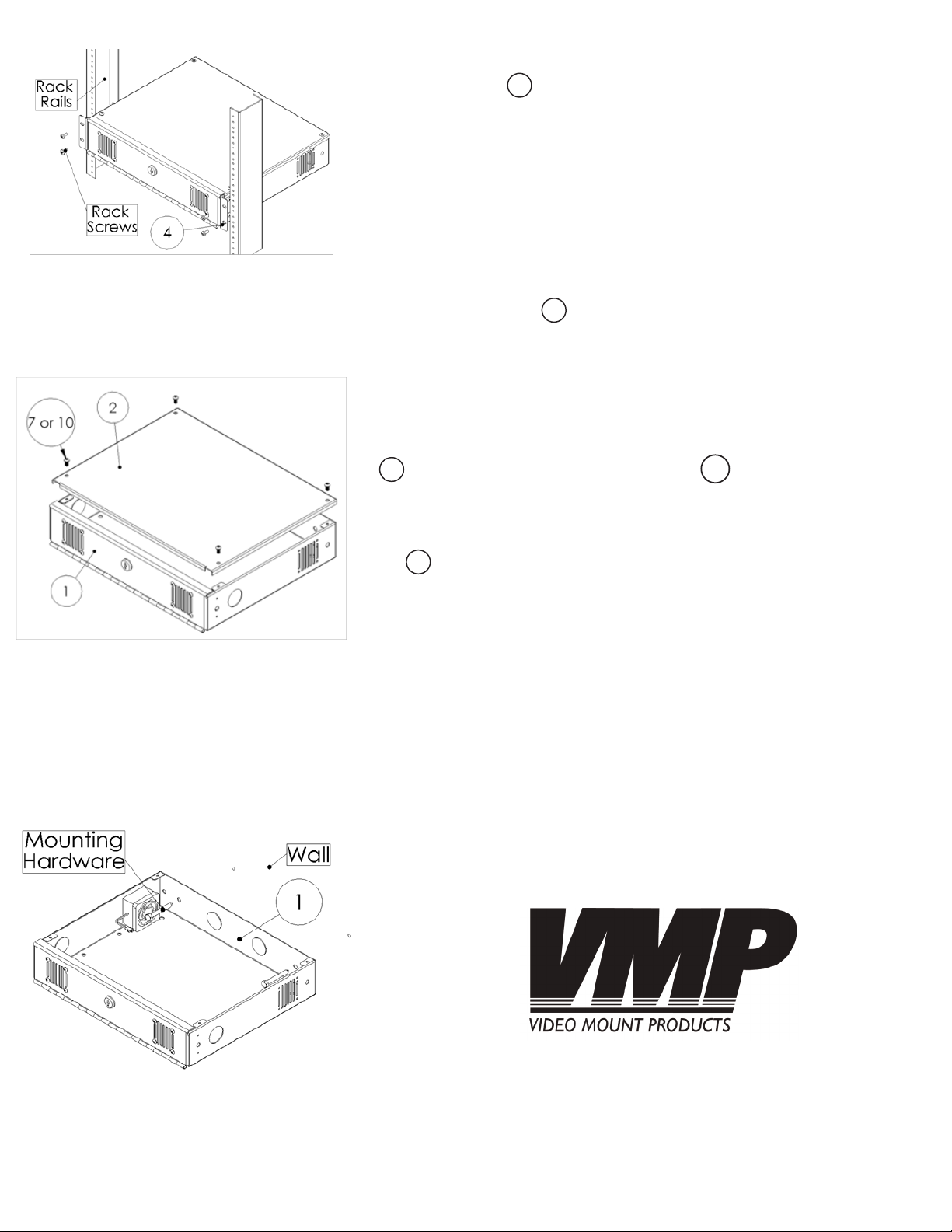
Step 7
Attach the Ears to the equipment rack using the appropriate
hardware for that particular equipment rack. Finish any wiring you
have to do.
4
Enjoy Your Mount!
If you are surface mounting the DVR-MB1...
Step 7
Step 8: Removing the Top Lid
Step 8
Remove the Top Lid to provide better access to the inside of
the box.
Step 9
Choose which side you wish to mount the DVR-MB1. The DVR-MB1
can be mounted on the left, right, rear and bottom sides. Note:
The only two sides which it cannot be mounted on are the Top Lid
2
and the front door of the Bottom Box . Pre-drill the mounting surface if necessary and mount the DVR-MB1 to the desired surface using appropriate hardware. Note: If mounting on the rear,
left or right sides some excess space is needed to reattach the Top
Lid when done. WARNING: Please verify that your mounting
2
surface will support the combined weight of your mount, mounting
hardware, and DVR. Also verify that the mounting surface is safe to
drill through. Please verify the mounting hardware used is the correct type of mounting hardware for your mounting surface before
installing. If in doubt or uncertain about any of the above, please
contact a professional installer.
2
1
Step 9: Mounting the Bottom Box
Step 10
Proceed to follow steps 3 through 5 written earlier in the instruc-
tions. Once nished those steps, make sure to nish any wiring still
necessary.
Please verify that all nuts and screws are securely tightened.
Enjoy Your Mount!
WARNING: The installer of these products must verify that the
mount surface, ceiling or wall, will safely support the combined weight of all attached equipment and hardware. Video Mount Products will not be held liable for the improper use
or installation of its products
 Loading...