

VMIC VMIVME-7740 Product Manual

VMIVME-7740
StockCheck.com
Single Board Pentium III Processor-Based VMEbus SBC
Product Manual
12090 South Memorial Parkway
Huntsville, Alabama 35803-3308, USA
(256) 880-0444
w (800) 322-3616 w Fax: (256) 882-0859
500-007740-000 Rev. A

12090 South Memorial Parkway
StockCheck.com
Huntsville, Alabama 35803-3308, USA
(256) 880-0444
w (800) 322-3616 w Fax: (256) 882-0859

COPYRIGHT AND TRADEMARKS
StockCheck.com
© Copyright 2000. The information in this document has been carefully checked and is believed to be entirely reliable.
While all reasonable efforts to ensure accuracy have been taken in the preparation of this manual, VMIC assumes no
responsibility resulting from omissions or errors in this manual, or from the use of information contained herein.
VMIC reserves the right to make any changes, without notice, to this or any of VMIC’s products to improve reliability,
performance, function, or design.
VMIC does not assume any liability arising out of the application or use of any product or circuit described herein; nor
does VMIC convey any license under its patent rights or the rights of others.
For warranty and repair policies, refer to VMIC’s Standard Conditions of Sale.
AMXbus, BITMODULE, COSMODULE, DMAbus, IOMax
MAGICWARE, MEGAMODULE, PLC ACCELERATOR (ACCELERATION), Quick Link, RTnet, Soft Logic Link, SRTbus,
TESTCAL, “The Next Generation PLC”, The PLC Connection, TURBOMODULE, UCLIO, UIOD, UPLC, Visual Soft Logic
Control(ler),
trademarks and The I/O Experts, The I/O Systems Experts, The Soft Logic Experts, and The Total Solutions Provider are
service marks of VMIC.
The I/O man figure, IOWorks, IOWorks man figure, UIOC, Visual IOWorks, the VMIC logo, and
registered trademarks of VMIC.
ActiveX, Microsoft, Microsoft Access, MS-DOS, Visual Basic, Visual C++, Win32, Windows, Windows NT, and XENIX
are registered trademarks of Microsoft Corporation.
Celeron and MMX are trademarks, and Intel and Pentium are registered trademarks of Intel Corporation.
PICMG and CompactPCI are registered trademarks of PCI Industrial Computer Manufacturers’ Group.
Other registered trademarks are the property of their respective owners.
VMEaccess
(I/O man figure)
, VMEbus Access
, VMEmanager, VMEmonitor
(IOWorks man figure)
, IOWorks Foundation, IOWorks Manager, IOWorks Server,
, VMEnet, VMEnet II, and
VMEprobe
WinUIOC
are
are
VMIC
All Rights Reserved
This document shall not be duplicated, nor its contents used for any
purpose, unless granted express written permission from VMIC.

12090 South Memorial Parkway
StockCheck.com
Huntsville, Alabama 35803-3308, USA
(256) 880-0444
w (800) 322-3616 w Fax: (256) 882-0859

Table of Contents
StockCheck.com
Overview
Organization of the Manual
References
Safety Summary
Safety Symbols Used in This Manual
Notation and Terminology
Chapter 1 - VMIVME-7740 Features and Options
VMEbus Features
Chapter 2 - Installation and Setup
Unpacking Procedures
Hardware Setup
Installation
. . . . . . . . . . . . . . . . . . . . . . . . . . . . . . . . . . . . . . . . . . . . . . . . . . . . . . . . . . . . . . . . . . . . . . . . . . . . . . . . . . . . . 15
. . . . . . . . . . . . . . . . . . . . . . . . . . . . . . . . . . . . . . . . . . . . . . . . . . . . . . . . . . . . . . . . . . 16
. . . . . . . . . . . . . . . . . . . . . . . . . . . . . . . . . . . . . . . . . . . . . . . . . . . . . . . . . . . . . . . . . . . . . . . . . . . . . . . . . 17
. . . . . . . . . . . . . . . . . . . . . . . . . . . . . . . . . . . . . . . . . . . . . . . . . . . . . . . . . . . . . . . . . . . . . . . . . . . . 19
. . . . . . . . . . . . . . . . . . . . . . . . . . . . . . . . . . . . . . . . . . . . . . . . . . . . . . . . . 20
. . . . . . . . . . . . . . . . . . . . . . . . . . . . . . . . . . . . . . . . . . . . . . . . . . . . . . . . . . . . . . . . . . . 21
. . . . . . . . . . . . . . . . . . . . . . . . . . . . . . . . . . . . . . . . . . . . . . . . . . . . . . . . . . . . . . . . . . . . . . . . . . . 26
VMIVME-7740 Product Options
. . . . . . . . . . . . . . . . . . . . . . . . . . . . . . . . . . . . . . . . . . . . . . . . . . . . . . . . . . . . . . . . . . . . . . 29
. . . . . . . . . . . . . . . . . . . . . . . . . . . . . . . . . . . . . . . . . . . . . . . . . . . . . . . . . . . . . . . . . . . . . . . . . . . . . 30
. . . . . . . . . . . . . . . . . . . . . . . . . . . . . . . . . . . . . . . . . . . . . . . . . . . . . . . . . . . . . . . . . . . . . . . . . . . . . . . . . . 35
BIOS Setup
Front Panel Connectors
PMC Expansion Site Connectors
LED Definition
. . . . . . . . . . . . . . . . . . . . . . . . . . . . . . . . . . . . . . . . . . . . . . . . . . . . . . . . . . . . . . . . . . . . . . . . . . . . . 36
. . . . . . . . . . . . . . . . . . . . . . . . . . . . . . . . . . . . . . . . . . . . . . . . . . . . . . . . . . . . . . . . . 36
. . . . . . . . . . . . . . . . . . . . . . . . . . . . . . . . . . . . . . . . . . . . . . . . . . . . . . . . . . . . . . . . . . . . . . . . . . . 37
. . . . . . . . . . . . . . . . . . . . . . . . . . . . . . . . . . . . . . . . . . . . . . . . . . . . . . . . . . 27
. . . . . . . . . . . . . . . . . . . . . . . . . . . . . . . . . . . . . . . . . . . . . . . . . . . . . . 29
. . . . . . . . . . . . . . . . . . . . . . . . . . . . . . . . . . . . . . . . . . . . . . . . . . . . . . . . . 36
. . . . . . . . . . . . . . . . . . . . . . . . . . . . . . . . . . . . . 23
Chapter 3 - PC/AT Functions
CPU Socket
Physical Memory
Memory and Port Maps
Memory Map
I/O Port Map
PC/AT Interrupts
. . . . . . . . . . . . . . . . . . . . . . . . . . . . . . . . . . . . . . . . . . . . . . . . . . . . . . . . . . . . . . . . . . . . . . . . . . . . . . . . . 40
. . . . . . . . . . . . . . . . . . . . . . . . . . . . . . . . . . . . . . . . . . . . . . . . . . . . . . . . . . . . . . . . . . . . . . . . . . . . 40
. . . . . . . . . . . . . . . . . . . . . . . . . . . . . . . . . . . . . . . . . . . . . . . . . . . . . . . . . . . . . . . . . . . . . . 41
. . . . . . . . . . . . . . . . . . . . . . . . . . . . . . . . . . . . . . . . . . . . . . . . . . . . . . . . . . . . . . . . . . . . . . . . . . . . 41
. . . . . . . . . . . . . . . . . . . . . . . . . . . . . . . . . . . . . . . . . . . . . . . . . . . . . . . . . . . . . . . . . . . . . . . . . . . . 42
. . . . . . . . . . . . . . . . . . . . . . . . . . . . . . . . . . . . . . . . . . . . . . . . . . . . . . . . . . . . . . . . . . . . . . . . . . . . 44
. . . . . . . . . . . . . . . . . . . . . . . . . . . . . . . . . . . . . . . . . . . . . . . . . . . . . . . . . . . . . 39
5

VMIVME-7740 Product Manual
StockCheck.com
PCI Interrupts
I/O Ports
Video Graphics Adapter
Ethernet Controllers
10BaseT
100BaseTx
LANWorks
. . . . . . . . . . . . . . . . . . . . . . . . . . . . . . . . . . . . . . . . . . . . . . . . . . . . . . . . . . . . . . . . . . . . . . . . . . . . . . . . 48
. . . . . . . . . . . . . . . . . . . . . . . . . . . . . . . . . . . . . . . . . . . . . . . . . . . . . . . . . . . . . . . . . . . . . . . . . . . . . . . . . . . . . 49
. . . . . . . . . . . . . . . . . . . . . . . . . . . . . . . . . . . . . . . . . . . . . . . . . . . . . . . . . . . . . . . . . . . . . . 50
. . . . . . . . . . . . . . . . . . . . . . . . . . . . . . . . . . . . . . . . . . . . . . . . . . . . . . . . . . . . . . . . . . . . . . . . . . 51
. . . . . . . . . . . . . . . . . . . . . . . . . . . . . . . . . . . . . . . . . . . . . . . . . . . . . . . . . . . . . . . . . . . . . . . . . . . . . . . . . 51
. . . . . . . . . . . . . . . . . . . . . . . . . . . . . . . . . . . . . . . . . . . . . . . . . . . . . . . . . . . . . . . . . . . . . . . . . . . . . . 51
. . . . . . . . . . . . . . . . . . . . . . . . . . . . . . . . . . . . . . . . . . . . . . . . . . . . . . . . . . . . . . . . . . . . . . . . . . . . . . . 51
Chapter 4 - Embedded PC/RTOS Features
Timers
Flash Disk
Watchdog Timer
NVRAM
. . . . . . . . . . . . . . . . . . . . . . . . . . . . . . . . . . . . . . . . . . . . . . . . . . . . . . . . . . . . . . . . . . . . . . . . . . . . . . . . . . . . . . . 54
General
Timer Interrupt Status
Clearing the Interrupt
Timer Programming
Mode Definitions
Configuration
Functionality
Advanced Configuration
Time of Day Registers
Time of Day Alarm Registers
Watchdog Alarm Registers
Command Register
. . . . . . . . . . . . . . . . . . . . . . . . . . . . . . . . . . . . . . . . . . . . . . . . . . . . . . . . . . . . . . . . . . . . . . . . . . . . . . . . . . 54
. . . . . . . . . . . . . . . . . . . . . . . . . . . . . . . . . . . . . . . . . . . . . . . . . . . . . . . . . . . . . . . . . . . . 54
. . . . . . . . . . . . . . . . . . . . . . . . . . . . . . . . . . . . . . . . . . . . . . . . . . . . . . . . . . . . . . . . . . . . . 55
. . . . . . . . . . . . . . . . . . . . . . . . . . . . . . . . . . . . . . . . . . . . . . . . . . . . . . . . . . . . . . . . . . . . . . 55
Architecture
Writing
Reading
. . . . . . . . . . . . . . . . . . . . . . . . . . . . . . . . . . . . . . . . . . . . . . . . . . . . . . . . . . . . . . . . . . . . . . . . . . . . . . . . . . . 63
. . . . . . . . . . . . . . . . . . . . . . . . . . . . . . . . . . . . . . . . . . . . . . . . . . . . . . . . . . . . . . . . . . . . . . . . . . . . . . . . . . . . . . 73
. . . . . . . . . . . . . . . . . . . . . . . . . . . . . . . . . . . . . . . . . . . . . . . . . . . . . . . . . . . . . . . . . . . . . . . . . . 55
. . . . . . . . . . . . . . . . . . . . . . . . . . . . . . . . . . . . . . . . . . . . . . . . . . . . . . . . . . . . . . . . . . . . . . . . . . . . . . . 57
. . . . . . . . . . . . . . . . . . . . . . . . . . . . . . . . . . . . . . . . . . . . . . . . . . . . . . . . . . . . . . . . . . . . . . . . . . . . . 59
. . . . . . . . . . . . . . . . . . . . . . . . . . . . . . . . . . . . . . . . . . . . . . . . . . . . . . . . . . . . . . . . . . . . . . . . . 62
. . . . . . . . . . . . . . . . . . . . . . . . . . . . . . . . . . . . . . . . . . . . . . . . . . . . . . . . . . . . . . . . . . . . . . . . . . . . 63
. . . . . . . . . . . . . . . . . . . . . . . . . . . . . . . . . . . . . . . . . . . . . . . . . . . . . . . . . . . . . . . . . . . . . . . . . . . . . 64
. . . . . . . . . . . . . . . . . . . . . . . . . . . . . . . . . . . . . . . . . . . . . . . . . . . . . . . . . . . . . . . . . . 64
. . . . . . . . . . . . . . . . . . . . . . . . . . . . . . . . . . . . . . . . . . . . . . . . . . . . . . . . . . . . . . . . . . . . . . . . . . . . . 67
. . . . . . . . . . . . . . . . . . . . . . . . . . . . . . . . . . . . . . . . . . . . . . . . . . . . . . . . . . . . . . . . . . . . 69
. . . . . . . . . . . . . . . . . . . . . . . . . . . . . . . . . . . . . . . . . . . . . . . . . . . . . . . . . . . . . . 70
. . . . . . . . . . . . . . . . . . . . . . . . . . . . . . . . . . . . . . . . . . . . . . . . . . . . . . . . . . . . . . . 71
. . . . . . . . . . . . . . . . . . . . . . . . . . . . . . . . . . . . . . . . . . . . . . . . . . . . . . . . . . . . . . . . . . . . . . . 71
. . . . . . . . . . . . . . . . . . . . . . . . . . . . . . . . . . . . . . . . . . . . . 53
Chapter 5 - Maintenance
Maintenance Prints
. . . . . . . . . . . . . . . . . . . . . . . . . . . . . . . . . . . . . . . . . . . . . . . . . . . . . . . . . . . . . . . . . . . . . . . . . . . 75
Appendix A - Connector Pinouts
Dual Ethernet Connectors Pinout (J1, J7)
Video Connector Pinout (J3)
Serial Connector Pinout (P3)
USB Connector (J8)
Keyboard/Mouse Connector Pinout
6
. . . . . . . . . . . . . . . . . . . . . . . . . . . . . . . . . . . . . . . . . . . . . . . . . . . . . . . . . . . . . . . . . . . . . . . . . . 82
. . . . . . . . . . . . . . . . . . . . . . . . . . . . . . . . . . . . . . . . . . . . . . . . . . . . . . . . . . . . . . . . . . . 75
. . . . . . . . . . . . . . . . . . . . . . . . . . . . . . . . . . . . . . . . . . . . . . . . . . . . . . . . . 77
. . . . . . . . . . . . . . . . . . . . . . . . . . . . . . . . . . . . . . . . . . . . . . . . . . . . . . 79
. . . . . . . . . . . . . . . . . . . . . . . . . . . . . . . . . . . . . . . . . . . . . . . . . . . . . . . . . . . . . . . . . . 80
. . . . . . . . . . . . . . . . . . . . . . . . . . . . . . . . . . . . . . . . . . . . . . . . . . . . . . . . . . . . . . . . . . 81
. . . . . . . . . . . . . . . . . . . . . . . . . . . . . . . . . . . . . . . . . . . . . . . . . . . . . . . . . . . 83

Table of Contents
StockCheck.com
VMEbus Connector Pinout
. . . . . . . . . . . . . . . . . . . . . . . . . . . . . . . . . . . . . . . . . . . . . . . . . . . . . . . . . . . . . . . . . . . 84
Appendix B - System Driver Software
Driver Software Installation
Windows 98 SE (Second Edition)
Manual Installation of the 8255X Driver
Intel 69030 Video Driver
Windows NT (Version 4.0)
Appendix C - Phoenix BIOS
System BIOS Setup Utility
Help Window
Main Menu
QuickBoot
Setting The Time
Setting The Date
Legacy Diskette
Floppy Drive A
Floppy Drive B
Primary Master/Slave
Secondary Master
Keyboard Features
NumLock
Key Click
Keyboard Auto-Repeat Rate (Chars/Sec)
Keyboard Auto-Repeat Delay (sec)
Keyboard Test
System Memory
Extended Memory
Extended Memory
Console Redirection
Com Port Address
Baud Rate
Console Type
Flow Control
Console Connection
Console Redirection After POST
Advanced Menu
. . . . . . . . . . . . . . . . . . . . . . . . . . . . . . . . . . . . . . . . . . . . . . . . . . . . . . . . . . . . . . . . . . . . . . . . . . . . 93
. . . . . . . . . . . . . . . . . . . . . . . . . . . . . . . . . . . . . . . . . . . . . . . . . . . . . . . . . . . . . . . . . . . . . . . . . . . . . . . . . . 94
. . . . . . . . . . . . . . . . . . . . . . . . . . . . . . . . . . . . . . . . . . . . . . . . . . . . . . . . . . . . . . . . . . . . . . . . . . . . . . . 94
. . . . . . . . . . . . . . . . . . . . . . . . . . . . . . . . . . . . . . . . . . . . . . . . . . . . . . . . . . . . . . . . . . . . . . . . . 95
. . . . . . . . . . . . . . . . . . . . . . . . . . . . . . . . . . . . . . . . . . . . . . . . . . . . . . . . . . . . . . . . . . . . . . . . . . . 96
. . . . . . . . . . . . . . . . . . . . . . . . . . . . . . . . . . . . . . . . . . . . . . . . . . . . . . . . . . . . . . . . . . . . . . . . . . . . 96
. . . . . . . . . . . . . . . . . . . . . . . . . . . . . . . . . . . . . . . . . . . . . . . . . . . . . . . . . . . . . . . . . . . . . . . . . . 98
. . . . . . . . . . . . . . . . . . . . . . . . . . . . . . . . . . . . . . . . . . . . . . . . . . . . . . . . . . . . . . . . . . . . . . . . . . . . . 99
. . . . . . . . . . . . . . . . . . . . . . . . . . . . . . . . . . . . . . . . . . . . . . . . . . . . . . . . . . . . . . . . . . 89
. . . . . . . . . . . . . . . . . . . . . . . . . . . . . . . . . . . . . . . . . . . . . . . . . . . . . . . . . . . . 90
. . . . . . . . . . . . . . . . . . . . . . . . . . . . . . . . . . . . . . . . . . . . . . . . . . . . . . . . . . . . . . . . . 90
. . . . . . . . . . . . . . . . . . . . . . . . . . . . . . . . . . . . . . . . . . . . . . . . . . . . . . . . . . . . . . . . . . . 91
. . . . . . . . . . . . . . . . . . . . . . . . . . . . . . . . . . . . . . . . . . . . . . . . . . . . . . . . . . . . . . 93
. . . . . . . . . . . . . . . . . . . . . . . . . . . . . . . . . . . . . . . . . . . . . . . . . . . . . . . . . . . . . . . 93
. . . . . . . . . . . . . . . . . . . . . . . . . . . . . . . . . . . . . . . . . . . . . . . . . . . . . . . . . . . . . . . . . . . . . . . . 94
. . . . . . . . . . . . . . . . . . . . . . . . . . . . . . . . . . . . . . . . . . . . . . . . . . . . . . . . . . . . . . . . . . . . . . . . 94
. . . . . . . . . . . . . . . . . . . . . . . . . . . . . . . . . . . . . . . . . . . . . . . . . . . . . . . . . . . . . . . . . . . . . . 95
. . . . . . . . . . . . . . . . . . . . . . . . . . . . . . . . . . . . . . . . . . . . . . . . . . . . . . . . . . . . . . . . . . . . . . 95
. . . . . . . . . . . . . . . . . . . . . . . . . . . . . . . . . . . . . . . . . . . . . . . . . . . . . . . . . . . . . . . . . . . . 95
. . . . . . . . . . . . . . . . . . . . . . . . . . . . . . . . . . . . . . . . . . . . . . . . . . . . . . . . . . . . . . . . . . . . . . . 96
. . . . . . . . . . . . . . . . . . . . . . . . . . . . . . . . . . . . . . . . . . . . . . . . . . . . . . . . . . . . . . . . . . . . . . 96
. . . . . . . . . . . . . . . . . . . . . . . . . . . . . . . . . . . . . . . . . . . . . . . . . . . . . . . . . . . . . . . . . . . . . . 97
. . . . . . . . . . . . . . . . . . . . . . . . . . . . . . . . . . . . . . . . . . . . . . . . . . . . . . . . . . . . . . . . . . . . . . . . . 97
. . . . . . . . . . . . . . . . . . . . . . . . . . . . . . . . . . . . . . . . . . . . . . . . . . . . . . . . . . . . . . . . . . . . . . . 97
. . . . . . . . . . . . . . . . . . . . . . . . . . . . . . . . . . . . . . . . . . . . . . . . . . . . . . . . . . . . . . . . . . . . . . . 97
. . . . . . . . . . . . . . . . . . . . . . . . . . . . . . . . . . . . . . . . . . . . . . . . . . . . . . . . . . . . . . . . . . . . . 97
. . . . . . . . . . . . . . . . . . . . . . . . . . . . . . . . . . . . . . . . . . . . . . . . . . . . . . . . . . . . . . . . . . . 98
. . . . . . . . . . . . . . . . . . . . . . . . . . . . . . . . . . . . . . . . . . . . . . . . . . . . . . . . . . . . . . . . . . . . . . . 98
. . . . . . . . . . . . . . . . . . . . . . . . . . . . . . . . . . . . . . . . . . . . . . . . . . . . . . . . . . . . . . . . . . . . . . . . 98
. . . . . . . . . . . . . . . . . . . . . . . . . . . . . . . . . . . . . . . . . . . . . . . . . . . . . . . . . . . . . . . . . 98
. . . . . . . . . . . . . . . . . . . . . . . . . . . . . . . . . . . . . . . . . . . . . . . . . . . . . 98
. . . . . . . . . . . . . . . . . . . . . . . . . . . . . . . . . . . . . . . . . . . . . . . . . . 89
. . . . . . . . . . . . . . . . . . . . . . . . . . . . . . . . . . . . . . . . . . . . . . . . . . . 90
. . . . . . . . . . . . . . . . . . . . . . . . . . . . . . . . . . . . . . . . . . . . . 96
. . . . . . . . . . . . . . . . . . . . . . . . . . . . . . . . . . . . . . . . . . . . . . . . . . . 97
7

VMIVME-7740 Product Manual
StockCheck.com
Installed O/S
Reset Configuration Data
Cache Memory
I/O Device Configuration
Large Disk Access Mode
Local Bus IDE Adapter
Advanced Chipset Control
Graphics Aperture
Enable Memory Map
ECC Config
SERR Signal Configuration
Clear Watch Dog Timer Reset
Assign Interrupt to USB
Legacy USB Support
Power
Security
Boot Menu
Exit Menu
. . . . . . . . . . . . . . . . . . . . . . . . . . . . . . . . . . . . . . . . . . . . . . . . . . . . . . . . . . . . . . . . . . . . . . . . . . . . . . . . . . . . . . . 103
. . . . . . . . . . . . . . . . . . . . . . . . . . . . . . . . . . . . . . . . . . . . . . . . . . . . . . . . . . . . . . . . . . . . . . . . . . . . . . . . . . . . . . 104
. . . . . . . . . . . . . . . . . . . . . . . . . . . . . . . . . . . . . . . . . . . . . . . . . . . . . . . . . . . . . . . . . . . . . . . . . . . . . . . . . . . . 106
Exit Saving Changes
Exit Discarding Changes
Load Setup Defaults
Discard Changes
Save Changes
. . . . . . . . . . . . . . . . . . . . . . . . . . . . . . . . . . . . . . . . . . . . . . . . . . . . . . . . . . . . . . . . . . . . . . . . . . . . . 99
. . . . . . . . . . . . . . . . . . . . . . . . . . . . . . . . . . . . . . . . . . . . . . . . . . . . . . . . . . . . . . . . . . . . . . . . . . . 99
. . . . . . . . . . . . . . . . . . . . . . . . . . . . . . . . . . . . . . . . . . . . . . . . . . . . . . . . . . . . . . . . . . . . . . . . . . 102
. . . . . . . . . . . . . . . . . . . . . . . . . . . . . . . . . . . . . . . . . . . . . . . . . . . . . . . . . . . . . . . . . . . . . . . . . . . . . . . . . . . 105
. . . . . . . . . . . . . . . . . . . . . . . . . . . . . . . . . . . . . . . . . . . . . . . . . . . . . . . . . . . . . . . . . . . . . . . . . 106
. . . . . . . . . . . . . . . . . . . . . . . . . . . . . . . . . . . . . . . . . . . . . . . . . . . . . . . . . . . . . . . . . . . . . . . . . . . 106
. . . . . . . . . . . . . . . . . . . . . . . . . . . . . . . . . . . . . . . . . . . . . . . . . . . . . . . . . . . . . . . . . 99
. . . . . . . . . . . . . . . . . . . . . . . . . . . . . . . . . . . . . . . . . . . . . . . . . . . . . . . . . . . . . . . . . . 100
. . . . . . . . . . . . . . . . . . . . . . . . . . . . . . . . . . . . . . . . . . . . . . . . . . . . . . . . . . . . . . . . . 101
. . . . . . . . . . . . . . . . . . . . . . . . . . . . . . . . . . . . . . . . . . . . . . . . . . . . . . . . . . . . . . . . . . . 101
. . . . . . . . . . . . . . . . . . . . . . . . . . . . . . . . . . . . . . . . . . . . . . . . . . . . . . . . . . . . . . . . 101
. . . . . . . . . . . . . . . . . . . . . . . . . . . . . . . . . . . . . . . . . . . . . . . . . . . . . . . . . . . . . . . . . . . . 101
. . . . . . . . . . . . . . . . . . . . . . . . . . . . . . . . . . . . . . . . . . . . . . . . . . . . . . . . . . . . . . . . . 102
. . . . . . . . . . . . . . . . . . . . . . . . . . . . . . . . . . . . . . . . . . . . . . . . . . . . . . . . . . . 102
. . . . . . . . . . . . . . . . . . . . . . . . . . . . . . . . . . . . . . . . . . . . . . . . . . . . . . . . . . . . 102
. . . . . . . . . . . . . . . . . . . . . . . . . . . . . . . . . . . . . . . . . . . . . . . . . . . . . . . . . . . . . . . . . . . 102
. . . . . . . . . . . . . . . . . . . . . . . . . . . . . . . . . . . . . . . . . . . . . . . . . . . . . . . . . . . . . . . . . . . . . 102
. . . . . . . . . . . . . . . . . . . . . . . . . . . . . . . . . . . . . . . . . . . . . . . . . . . . . . . . . . . . . . . . . . . . . 106
. . . . . . . . . . . . . . . . . . . . . . . . . . . . . . . . . . . . . . . . . . . . . . . . . . . . . . . . . . . . . . . . . . 106
. . . . . . . . . . . . . . . . . . . . . . . . . . . . . . . . . . . . . . . . . . . . . . . . . . . . . . . . . . . . . . . . . . . . . . 106
Appendix D - LANWorks BIOS
Boot Menus
First Boot Menu
Boot Menu
BIOS Features Setup
RPL
TCP/IP
Netware
PXE
. . . . . . . . . . . . . . . . . . . . . . . . . . . . . . . . . . . . . . . . . . . . . . . . . . . . . . . . . . . . . . . . . . . . . . . . . . . . . . . . . . 108
. . . . . . . . . . . . . . . . . . . . . . . . . . . . . . . . . . . . . . . . . . . . . . . . . . . . . . . . . . . . . . . . . . . . . . . . . . 108
. . . . . . . . . . . . . . . . . . . . . . . . . . . . . . . . . . . . . . . . . . . . . . . . . . . . . . . . . . . . . . . . . . . . . . . . . . . . . . . 108
. . . . . . . . . . . . . . . . . . . . . . . . . . . . . . . . . . . . . . . . . . . . . . . . . . . . . . . . . . . . . . . . . . . . . . . . . 110
. . . . . . . . . . . . . . . . . . . . . . . . . . . . . . . . . . . . . . . . . . . . . . . . . . . . . . . . . . . . . . . . . . . . . . . . . . . . . . . . . . . . . 110
. . . . . . . . . . . . . . . . . . . . . . . . . . . . . . . . . . . . . . . . . . . . . . . . . . . . . . . . . . . . . . . . . . . . . . . . . . . . . . . . . . 110
. . . . . . . . . . . . . . . . . . . . . . . . . . . . . . . . . . . . . . . . . . . . . . . . . . . . . . . . . . . . . . . . . . . . . . . . . . . . . . . . . 111
. . . . . . . . . . . . . . . . . . . . . . . . . . . . . . . . . . . . . . . . . . . . . . . . . . . . . . . . . . . . . . . . . . . . . . . . . . . . . . . . . . . . . 111
Appendix E - Device Configuration: I/O and Interrupt Control
BIOS Operations
BIOS Control O v erview
Functional Overview
8
. . . . . . . . . . . . . . . . . . . . . . . . . . . . . . . . . . . . . . . . . . . . . . . . . . . . . . . . . . . . . . . . . . . . . . . . . . . . . 114
. . . . . . . . . . . . . . . . . . . . . . . . . . . . . . . . . . . . . . . . . . . . . . . . . . . . . . . . . . . . . . . . . . . 114
. . . . . . . . . . . . . . . . . . . . . . . . . . . . . . . . . . . . . . . . . . . . . . . . . . . . . . . . . . . . . . . . . . . . . . 114
. . . . . . . . . . . . . . . . . . . . . . . . . . . . . . . . . . . . . . . . . . . . . . . . . . . . . . . . . . . . 107
. . . . . . . . . . . . . . . . . . . . . . 113

Table of Contents
StockCheck.com
Data Book References
Device Address Definition
ISA Devices
PCI Devices
Device Interrupt Definition
PC/AT Interrupt Definition
ISA Device Interrupt Map
PCI Device Interrupt Map
. . . . . . . . . . . . . . . . . . . . . . . . . . . . . . . . . . . . . . . . . . . . . . . . . . . . . . . . . . . . . . . . . . . . . . . . . . . . . 118
. . . . . . . . . . . . . . . . . . . . . . . . . . . . . . . . . . . . . . . . . . . . . . . . . . . . . . . . . . . . . . . . . . . . . . . . . . . . . 119
. . . . . . . . . . . . . . . . . . . . . . . . . . . . . . . . . . . . . . . . . . . . . . . . . . . . . . . . . . . . . . . . . . . 116
. . . . . . . . . . . . . . . . . . . . . . . . . . . . . . . . . . . . . . . . . . . . . . . . . . . . . . . . . . . . . . . . . . . 118
. . . . . . . . . . . . . . . . . . . . . . . . . . . . . . . . . . . . . . . . . . . . . . . . . . . . . . . . . . . . . . . . . . . 120
. . . . . . . . . . . . . . . . . . . . . . . . . . . . . . . . . . . . . . . . . . . . . . . . . . . . . . . . . . . . . . . . 120
. . . . . . . . . . . . . . . . . . . . . . . . . . . . . . . . . . . . . . . . . . . . . . . . . . . . . . . . . . . . . . . . 120
. . . . . . . . . . . . . . . . . . . . . . . . . . . . . . . . . . . . . . . . . . . . . . . . . . . . . . . . . . . . . . . . 122
Appendix F - Sample C Software
Directory CPU
CPU.C
** FILE: CPU.H
** FILE: FLAT.C
** FILE: FLAT.H
** FILE: PCI.C
** FILE: PCI.H
** FILE: UNIVERSE.H
Directory SRAM
** FILE: TS.C
Directory Timers
CPU.H
** FILE: T_TIMERS.C
Directory WATCHDOG
** FILE: WATCHDOG.H
** FILE:WDTO.C
. . . . . . . . . . . . . . . . . . . . . . . . . . . . . . . . . . . . . . . . . . . . . . . . . . . . . . . . . . . . . . . . . . . . . . . . . . . . . . . 124
. . . . . . . . . . . . . . . . . . . . . . . . . . . . . . . . . . . . . . . . . . . . . . . . . . . . . . . . . . . . . . . . . . . . . . . . . . . . . . . . . . 124
. . . . . . . . . . . . . . . . . . . . . . . . . . . . . . . . . . . . . . . . . . . . . . . . . . . . . . . . . . . . . . . . . . . . . . . . . 134
. . . . . . . . . . . . . . . . . . . . . . . . . . . . . . . . . . . . . . . . . . . . . . . . . . . . . . . . . . . . . . . . . . . . . . . . 135
. . . . . . . . . . . . . . . . . . . . . . . . . . . . . . . . . . . . . . . . . . . . . . . . . . . . . . . . . . . . . . . . . . . . . . . 143
. . . . . . . . . . . . . . . . . . . . . . . . . . . . . . . . . . . . . . . . . . . . . . . . . . . . . . . . . . . . . . . . . . . . . . . . . . 145
. . . . . . . . . . . . . . . . . . . . . . . . . . . . . . . . . . . . . . . . . . . . . . . . . . . . . . . . . . . . . . . . . . . . . . . . . . 149
. . . . . . . . . . . . . . . . . . . . . . . . . . . . . . . . . . . . . . . . . . . . . . . . . . . . . . . . . . . . . . . . . . 151
. . . . . . . . . . . . . . . . . . . . . . . . . . . . . . . . . . . . . . . . . . . . . . . . . . . . . . . . . . . . . . . . . . . . . . . . . . . . . 191
. . . . . . . . . . . . . . . . . . . . . . . . . . . . . . . . . . . . . . . . . . . . . . . . . . . . . . . . . . . . . . . . . . . . . . . . . . . 191
. . . . . . . . . . . . . . . . . . . . . . . . . . . . . . . . . . . . . . . . . . . . . . . . . . . . . . . . . . . . . . . . . . . . . . . . . . . . . 195
. . . . . . . . . . . . . . . . . . . . . . . . . . . . . . . . . . . . . . . . . . . . . . . . . . . . . . . . . . . . . . . . . . . . . . . . . . . . . . . . . . 195
. . . . . . . . . . . . . . . . . . . . . . . . . . . . . . . . . . . . . . . . . . . . . . . . . . . . . . . . . . . . . . . . . . 197
. . . . . . . . . . . . . . . . . . . . . . . . . . . . . . . . . . . . . . . . . . . . . . . . . . . . . . . . . . . . . . . . . . . . . . 209
. . . . . . . . . . . . . . . . . . . . . . . . . . . . . . . . . . . . . . . . . . . . . . . . . . . . . . . . . . . . . . . . . 209
. . . . . . . . . . . . . . . . . . . . . . . . . . . . . . . . . . . . . . . . . . . . . . . . . . . . . . . . . . . . . . . . . . . . . . . . 210
. . . . . . . . . . . . . . . . . . . . . . . . . . . . . . . . . . . . . . . . . . . . . . . . . . . . . . . . 123
9

VMIVME-7740 Product Manual
StockCheck.com
10

List of Figures
StockCheck.com
Figure 1-1 VMIVME-7740 Block Diagram
Figure 1-2 VMIVME-7740 VMEbus Functions
Figure 2-1 VMIVME-7740 CPU Board, I/O Port,
Figure 2-2 PCI Expansion Site
Figure 2-3 LED Position on the Front Panel
Figure 3-1 Connections for the PC Interrupt Logic Controller
Figure 4-1 Timer Interrupt Status Register Read/Steps
Figure 4-2 Timer Interrupt Status Register
Figure 4-3 Clearing the Timer Interrupt Status Register
Figure 4-4 82C54 Diagram
Figure 4-5 Internal Timer Diagram
Figure 4-6 Typical System Configuration
Figure 4-7 Watchdog Alarm Block
Figure A-1 VMIVME-7740 Connector and Jumper Locations
Figure A-2 Ethernet Connector Pinout
Figure A-3 Video Connector Pinout
Figure A-4 Serial Connector Pinouts
Figure A-5 USB Connector and Pinout
Figure A-6 Keyboard Connector Pinout
Figure A-7 VME64 Connector Diagram
Figure E-1 VMIVME-7740 Block Diagram
115
Figure E-2 BIOS Default Connections for the PC Interrupt Logic Controller
121
and Jumper Locations
. . . . . . . . . . . . . . . . . . . . . . . . . . . . . . . . . . . . . . . . . . . . . . . . . . . . . . . . . . . . .
. . . . . . . . . . . . . . . . . . . . . . . . . . . . . . . . . . . . . . . . . . . . . . . . . . . . . . . . . . . . . . . .
. . . . . . . . . . . . . . . . . . . . . . . . . . . . . . . . . . . . . . . . . . . . . . . . . . . . . . . . . .
. . . . . . . . . . . . . . . . . . . . . . . . . . . . . . . . . . . . . . . . . . . . . . . . . . . . . . . . . .
. . . . . . . . . . . . . . . . . . . . . . . . . . . . . . . . . . . . . . . . . . . . . . . . . . .
. . . . . . . . . . . . . . . . . . . . . . . . . . . . . . . . . . . . . . . . . . . . . .
. . . . . . . . . . . . . . . . . . . . . . . . . . . . . . . . . . . . . . . . . . . . . . . .
. . . . . . . . . . . . . . . . . . . . . . . . . . . . . . . .
. . . . . . . . . . . . . . . . . . . . . . . . . . . . . . . . . . . . . .
. . . . . . . . . . . . . . . . . . . . . . . . . . . . . . . . . . . . . . . . . . . . . . . . . .
. . . . . . . . . . . . . . . . . . . . . . . . . . . . . . . . . . . . .
. . . . . . . . . . . . . . . . . . . . . . . . . . . . . . . . . . . . . . . . . . . . . . . . . . . . . . . . .
. . . . . . . . . . . . . . . . . . . . . . . . . . . . . . . . . . . . . . . . . . . . . . . . . . .
. . . . . . . . . . . . . . . . . . . . . . . . . . . . . . . . .
. . . . . . . . . . . . . . . . . . . . . . . . . . . . . . . . . . . . . . . . . . . . . . . . . . . . . .
. . . . . . . . . . . . . . . . . . . . . . . . . . . . . . . . . . . . . . . . . . . . . . . . . . . . . . . . .
. . . . . . . . . . . . . . . . . . . . . . . . . . . . . . . . . . . . . . . . . . . . . . . . . . . . . . .
. . . . . . . . . . . . . . . . . . . . . . . . . . . . . . . . . . . . . . . . . . . . . . . . . . . . .
. . . . . . . . . . . . . . . . . . . . . . . . . . . . . . . . . . . . . . . . . . . . . . . . . . . .
. . . . . . . . . . . . . . . . . . . . . . . . . . . . . . . . . . . . . . . . . . . . . . . . . . . . .
. . . . . . . . . . . . . . . . . . . . . . . . . . . . . . . . . . . . . . . . . . . . . . . . . . .
25
27
31
36
37
49
54
55
55
56
57
63
67
78
79
80
81
82
83
84
. . . . . . . . . . . . . . . . . . .
11

VMIVME-7740 Product Manual
StockCheck.com
12

List of Tables
StockCheck.com
Table 1-1 PC/AT I/O Features . . . . . . . . . . . . . . . . . . . . . . . . . . . . . . . . . . . . . . . . . . . . . . . . . . 24
Table 2-1 CPU Board Connectors . . . . . . . . . . . . . . . . . . . . . . . . . . . . . . . . . . . . . . . . . . . . . . . 32
Table 2-2 Timers and NVRAM Battery Select (User Configurable) - Jumper (E8) . . . . . . . . . . 32
Table 2-5 CMOS Battery Enable - Jumper (E10) . . . . . . . . . . . . . . . . . . . . . . . . . . . . . . . . . . . . 33
Table 2-3 BIOS Mode Option - Jumper (E15) . . . . . . . . . . . . . . . . . . . . . . . . . . . . . . . . . . . . . . 33
Table 2-4 Password Clear (User Configurable) - Jumper (E4) . . . . . . . . . . . . . . . . . . . . . . . . . 33
Table 2-6 VME Interface Jumper Options and Factory Settings (E13, E14) . . . . . . . . . . . . . . . 34
Table 3-1 VMIVME-7740, Universe II-Based Interface Memory Address Map . . . . . . . . . . . . . 41
Table 3-2 VMIVME-7740 I/O Address Map . . . . . . . . . . . . . . . . . . . . . . . . . . . . . . . . . . . . . . . . 42
Table 3-3 PC/AT Hardware Interrupt Line Assignments . . . . . . . . . . . . . . . . . . . . . . . . . . . . . . 44
Table 3-4 PC/AT Interrupt Vector Table . . . . . . . . . . . . . . . . . . . . . . . . . . . . . . . . . . . . . . . . . . 45
Table 3-5 NMI Register Bit Descriptions . . . . . . . . . . . . . . . . . . . . . . . . . . . . . . . . . . . . . . . . . . 48
Table 3-6 Supported Graphics Video Resolutions . . . . . . . . . . . . . . . . . . . . . . . . . . . . . . . . . . . 50
Table 4-1 I/O Address of the Control Word Register and Timers . . . . . . . . . . . . . . . . . . . . . . . . 55
Table 4-2 Control Word Format . . . . . . . . . . . . . . . . . . . . . . . . . . . . . . . . . . . . . . . . . . . . . . . . . 57
Table 4-3 ST - Select Timer . . . . . . . . . . . . . . . . . . . . . . . . . . . . . . . . . . . . . . . . . . . . . . . . . . . . 58
Table 4-4 RW - Read/Write . . . . . . . . . . . . . . . . . . . . . . . . . . . . . . . . . . . . . . . . . . . . . . . . . . . . 58
Table 4-5 M - Mode . . . . . . . . . . . . . . . . . . . . . . . . . . . . . . . . . . . . . . . . . . . . . . . . . . . . . . . . . . 58
Table 4-6 BCD . . . . . . . . . . . . . . . . . . . . . . . . . . . . . . . . . . . . . . . . . . . . . . . . . . . . . . . . . . . . . . 59
Table 4-7 Read-Back Command Format . . . . . . . . . . . . . . . . . . . . . . . . . . . . . . . . . . . . . . . . . . 60
Table 4-8 Read-Back Command Description . . . . . . . . . . . . . . . . . . . . . . . . . . . . . . . . . . . . . . . 60
Table 4-9 Status Byte . . . . . . . . . . . . . . . . . . . . . . . . . . . . . . . . . . . . . . . . . . . . . . . . . . . . . . . . . 60
Table 4-10 Status Byte Description . . . . . . . . . . . . . . . . . . . . . . . . . . . . . . . . . . . . . . . . . . . . . . . 61
Table 4-11 LOAD Bit Operation . . . . . . . . . . . . . . . . . . . . . . . . . . . . . . . . . . . . . . . . . . . . . . . . . . 61
Table 4-12 Watchdog Registers . . . . . . . . . . . . . . . . . . . . . . . . . . . . . . . . . . . . . . . . . . . . . . . . . . 68
Table 4-13 Time of Day Alarm Registers . . . . . . . . . . . . . . . . . . . . . . . . . . . . . . . . . . . . . . . . . . . 70
Table A-1 Keyboard/Mouse Y Splitter Cable . . . . . . . . . . . . . . . . . . . . . . . . . . . . . . . . . . . . . . . 83
Table A-2 P1 - VME64 Connector . . . . . . . . . . . . . . . . . . . . . . . . . . . . . . . . . . . . . . . . . . . . . . . 84
Table A-3 P2 - VME64 Connector . . . . . . . . . . . . . . . . . . . . . . . . . . . . . . . . . . . . . . . . . . . . . . . 86
Table E-1 ISA Device Mapping Configuration . . . . . . . . . . . . . . . . . . . . . . . . . . . . . . . . . . . . . .
118
Table E-2 PCI Device Mapping Configuration . . . . . . . . . . . . . . . . . . . . . . . . . . . . . . . . . . . . . .
119
Table E-3 Device PCI Interrupt Mapping by the BIOS . . . . . . . . . . . . . . . . . . . . . . . . . . . . . . . .
13

VMIVME-7740 Product Manual
StockCheck.com
122
14

Overview
StockCheck.com
Introduction
VMIC’s VMIVME-7740 is a complete Pentium III processor-based computer with the
additional benefits of single Eurocard construction and full compatibility with the
VMEbus Specification Rev. C.1. The VMIVME-7740, with advanced VMEbus interface
and RAM that is dual-ported to the VMEbus, is ideal for multiprocessor applications.
The single CPU board functions as a standard PC/AT, executing a PC/AT-type
power-on self-test, then boots up MS-DOS, Windows 95, Windows NT, or any other
PC compatible operating system. The standard PC features of the VMIVME-7740 are
discussed in Chapter 3 of this manual.
The VMIVME-7740 also operates as a VMEbus controller and interacts with other
VMEbus modules via the on-board PCI-to-VMEbus bridge and the Endian conversion
hardware.
The VMIVME-7740 may be accessed as a VMEbus slave board. The VMEbus functions
are available by programming the VMIVME-7740’s PCI-to-VMEbus bridge according
to the references defined in this volume and/or in the second volume dedicated to the
optional PCI-to-VMEbus interface board titled: VMIVME-7740 Tundra Univer se
™-Based VMEbus Interface Product Manual (document No. 500-007740-001).
II
Throughout this manual, all references to the Universe II refer to the Universe IIB.
The VMIVME-7740 programmer may quickly and easily control all the VMEbus
functions simply by linking to a libra ry of VMEbus interrupt and control functions.
This library is available with VMIC’s VMISFT-9420 IOWorks Access software for
Windows NT users.
The VMIVME-7740 also provides capabilities beyond the features of a typical
PC/AT-compatible SBC including general-purpose timers, a programmable
Watchdog Timer, a bootable flash disk system, and nonvolatile SRAM. These features
make the unit ideal for embedded applications. These nonstandard PC/AT functions
are discussed in Chapter 4 of this manual.
15

VMIVME-7740 Product Manual
StockCheck.com
Organization of the Manual
This manual is composed of the following chapters and appendices:
Chapter 1 - VMIVME-774 0 Features and Options describes the features of the base
unit followed by descriptions of the associated features of the unit in operation on a
VMEbus.
Chapter 2 - Installation and Setup describes unpacking, inspection, hardware jumper
settings, connector definitions, installation, system setup, and operation of the
VMIVME-7740.
Chapter 3 - PC/AT Functions describes the unit design in terms of the standard PC
memory and I/O maps, along with the standard interrupt architecture.
Chapter 4 - Embedded PC/RTOS Features describes the unit features that are beyond
standard PC/AT functions.
Chapter 5 - Maintenance provides information relative to the car e and maintena nce of
the unit.
Appendix A - Connector Pinouts illustrates and defines the connectors included in the
unit’s I/O ports.
Appendix B - System Driver Software includes detailed instructions for installation of
the drivers during installation of Windows 95, 98, 2000, or Windows NT (Version 4.0)
operating systems.
Appendix C - Phoenix BIOS describes the menus and options associated with the
Phoenix BIOS.
Appendix D - LANWorks BIOS describes the menus and options associated with the
LANWorks BIOS.
Appendix D - Device Configuration: I/O and Interrupt Control provides the user with
the information needed to develop custom applications such as the revision of the
current BIOS configuration to a user-specific configuration.
Appendix E - Sample C Software provides a library of sample code the programmers
may utilize to build the required application software for their system.
16

References
StockCheck.com
For the most up-to-date specifications for the VMIVME-7740, please refer to:
VMIC specification number 800-007740-000
The following books refer to the Tundra Universe II-based interface available in the
VMIVME-7740:
VMIVME-7740, Tundra Universe II™-Based VMEbus Interface Product Manual
VMIC Doc. No. 500-007740-001
VMEbus Interface Components Manual
Tundra Semiconductor Corporation
603 March Rd.
Kanata, Ontario
Canada, K2K 2M5
(613) 592-0714 FAX (613) 592-1320
www.tundra.com
Some reference sources helpful in using or programming the VMIVME-7740 include:
Pentium III Processors and Related Products
Intel Literature Sales
P.O. Box 7641
Mt. Prospect, IL 60056-7641
(800) 548-4752
www.intel.com
References
Intel 440GX PCIset
82443GX PCI and Memory Controller (PMC) 82443GX AGP set
Intel Corporation
P.O. Box 58119
Santa Clara, CA 95052-8119
(408) 765-8080
www.intel.com
PCI Special Interest Group
P.O. Box 14070
Portland, OR 97214
(800) 433-5177 (U.S.) (503) 797-4207 (International) FAX (503) 234-6762
www.pcisig.com
The VMEbus interrupt and control software library references included for
Windows NT:
VMISFT-9420 IOWorks Access User’s Guide
Doc. No. 520-009420-910
VMIC
12090 South Memorial Pkwy.
Huntsville, AL 35803-3308
(800) 322-3616 FAX: (256) 882-0859
www.vmic.com
17

VMIVME-7740 Product Manual
StockCheck.com
For a detailed description and specification of the VMEbus, please refer to:
VMEbus Specification Rev. C.1 and The VMEbus Handbook
The following is useful information related to remote Ethernet booting of the
VMIVME-7740:
VMEbus International Trade Association (VITA)
7825 East Gelding Dr.
Suite No. 104
Scottsdale, AZ 85260
(602) 951-8866 FAX: (602) 951-0720
www.vita.com
Microsoft Windows NT Server Resource Kit
Microsoft Corporation
ISBN: 1-57231-344-7
www.microsoft.com
18

Safety Summary
StockCheck.com
The following general safety precautions must be observed during all phases of the
operation, service, and repair of this product. Failure to comply with these
precautions or with specific warnings elsewhere in this manual violates safety
standards of design, manufacture, and intended use of this product.
VMIC assumes no liability for the customer’s failure to comply with these
requirements.
Ground the System
To minimize shock hazard, the chassis and system cabinet must be connected to an
electrical ground. A three-conductor AC power cable should be used. The power
cable must either be plugged into an approved three-contact electrical outlet or used
with a three-contact to two-contact adapter with the grounding wire (green) firmly
connected to an electrical ground (safety ground) at the power outlet.
Do Not Operate in an Explosive Atmosphere
Do not operate the system in the presence of flammable gases or fumes. Operation of
any electrical system in such an environment constitutes a definite safety hazard.
Safety Summary
Keep Away from Live Circuits
Operating personnel must not remove product covers. Component replacement and
internal adjustments must be made by qualified maintena nce personnel. Do not
replace components with power cable connected. Under certain conditions,
dangerous voltages may exist even with the power cable removed. To avoid injuries,
always disconnect power and discharge circuits before touching them.
Do Not Service or Adjust Alone
Do not attempt internal service or adjustment unless another person capable of
rendering first aid and resuscitation is present.
Do Not Substitute Parts or Modify System
Because of the danger of introducing additional hazards, do not install substitute
parts or perform any unauthorized modification to the product. Return the product to
VMIC for service and repair to ensure that safety features are maintained.
Dangerous Procedure Warnings
Warnings, such as the example below , pr ecede only po tentially danger ous procedur es
throughout this manual. Instructions contained in the warnings must be followed.
WARNING: Dangerous voltages, capable of causing death, are presen t in this system.
Use extreme caution when handling, testing, and adjusting.
19
VMIVME-7740 Product Manual
StockCheck.com
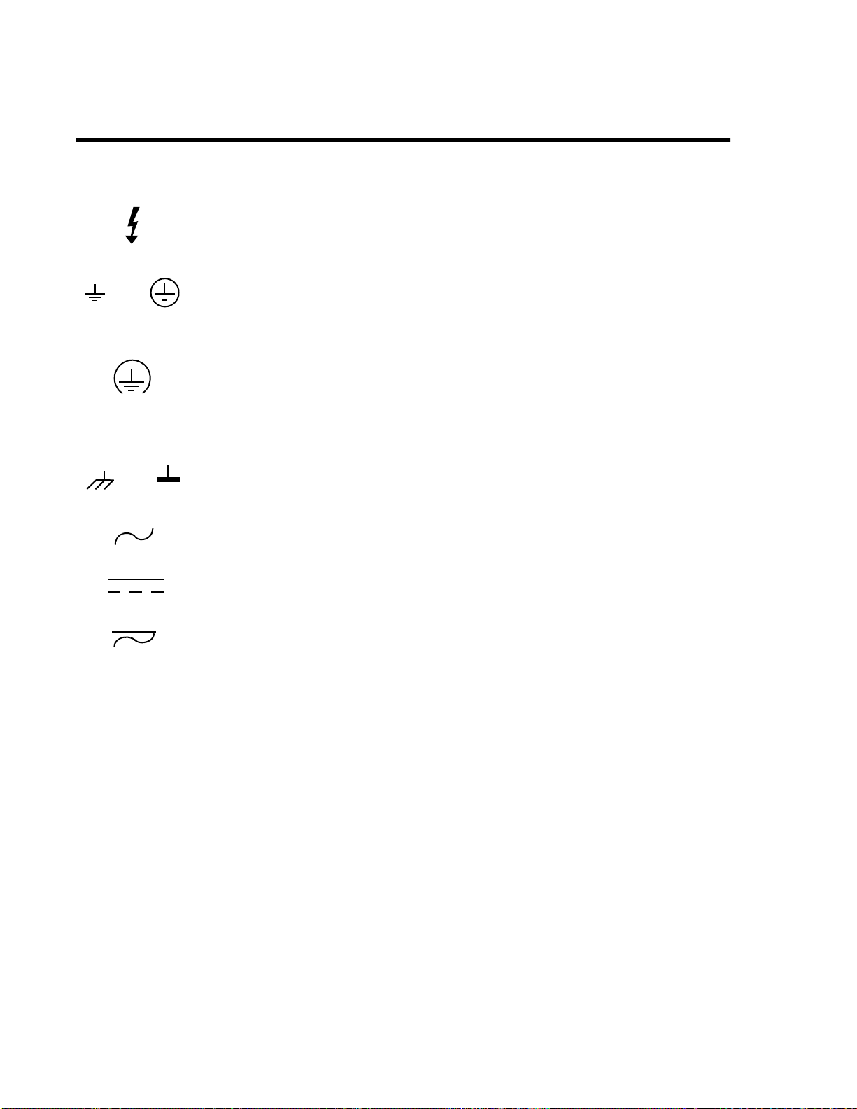
Safety Symbols Used in This Manual
Indicates dangerous voltage (terminals fed from the interior by voltage exceeding
1000 V are so marked).
OR
OR
Protective conductor terminal. For protection against electrical shock in case of a fault.
Used with field wiring terminals to indicate the terminal which must be connected to
ground before operating equipment.
Low-noise or noiseless, clean ground (earth) terminal. Used for a signal common, as
well as providing protection against electrical shock in case of a fault. Before
operating the equipment, terminal marked with this symbol must be connected to
ground in the manner described in the installation (operation) manual.
Frame or chassis terminal. A connection to the frame (chassis) of the equipment which
normally includes all exposed metal structures.
Alternating current (power line).
Direct current (power line).
Alternating or direct current (power line).
STOP informs the operator that the practice or procedure should not be performed.
Actions could result in injury or death to personnel, or could result in damage to or
destruction of part or all of the system.
WARNING denotes a hazard. It calls attention to a procedure, a practice, or
condition, which, if not correctly performed or adhered to, could result in injury or
death to personnel.
CAUTION denotes a hazard. It calls attention to an operating procedure, a practice,
or condition, which, if not correctly performed or adhered to, could result in damage
to or destruction of part or all of the system.
NOTE denotes important information. It calls attention to a procedure, a practice, a
condition or the like, which is essential to highlight.
20

Notation and Terminology
StockCheck.com
This product bridges the traditionally divergent worlds of Intel-based PC’s and
Motorola-based VMEbus controllers; therefore, some confusion over “conventional”
notation and terminology may exist. Every effort has been made to make this manual
consistent by adhering to conventions typical for the Motorola/VMEbus world;
nevertheless, users in both camps should review the following notes:
• Hexadecimal numbers are listed Motorola-style, prefixed with a dollar sign:
$F79, for example. By contrast, this same number would be signified 0F79H
according to the Intel convention, or 0xF79 by many programmers. Less
common are forms such as F79
• An 8-bit quantity is termed a “byte,” a 16-bit quantit y is termed a “wor d,” and a
32-bit quantity is termed a “longword.” The Intel convention is similar,
although their 32-bit quantity is more often called a “doubleword.”
• Motorola programmers should note that Intel processors have an I/O bus that
is completely independent from the memory bus. Every effort has been made in
the manual to clarify this by referring to registers and logical entities in I/O
space by prefixing I/O addresses as such. Thus, a register at “I/O $140” is not
the same as a register at “$140,” since the latter is on the memory bus while the
former is on the I/O bus.
• Intel programmers should note that addresses are listed in this manual using a
linear, “flat-memory” model rather than the old segment:offset model
associated with Intel Real Mo de programm ing. Thus, a ROM chip at a
segment:offset address of C000:0 will be listed in this manual as being at
address $C0000. For reference, here are some quick conversion formulas:
or the mathematician’s F7916.
h
Notation and Terminology
Segment:Offset to Linear Address
Linear Address = (Segment × 16) + Offset
Linear Address to Segment:Offset
Segment = ((Linear Address ÷ 65536) − remainder) × 4096
Offset = remainder × 65536
Where remainder = the fractional part of (Linear Address ÷ 65536)
Note that there are many possible segment:offset addresses for a single location. The
formula above will provide a unique segment:offset address by forcing the segment to
an even 64 Kbyte boundary, for example, $C000, $E000, etc. When using this formula,
make sure to round the offset calculation properly.
21

VMIVME-7740 Product Manual
StockCheck.com
22

VMIVME-7740 Features and
StockCheck.com
Options
Contents
Introduction . . . . . . . . . . . . . . . . . . . . . . . . . . . . . . . . . . . . . . . . . . . . . . . . . . . . . . . . 23
VMEbus Features. . . . . . . . . . . . . . . . . . . . . . . . . . . . . . . . . . . . . . . . . . . . . . . . . . . . 26
CHAPTER
1
Introduction
The VMIVME-7740 performs all the functions of a standard IBM PC/AT motherboard
with the following features:
• S ingle-slot VMEbus 6U size
• Includes a high-performance Intel Pentium III processor
• Up to 512 Mbyte of Synchronous DRAM
• 64-bit AGP SVGA video graphics accelerator
- 4 Mbyte SGRAM Video Memory
- Resolutions up to 1600x1200x56k colors
• Battery-backed clock/calendar
• Front pane l reset switch and miniature speaker
• On-board port for a keyboard and mouse, Ultra-IDE hard drive, floppy drive,
dual Ethernet, video, dual serial, and USB
• Front panel “vital sign” indicators (power, Ultra-IDE hard drive activity,
VMEbus SYSFAIL, and Ethernet status)
• Three general-purpose programmable 16-bit timers
• Software-controlled Watchdog Timer
• Up to 192 Mbyte of bootable flash on secondary IDE
• 32 Kbyte of non-volatile SRAM
•PMC
23
1
StockCheck.com
VMIVME-7740 Product Manual
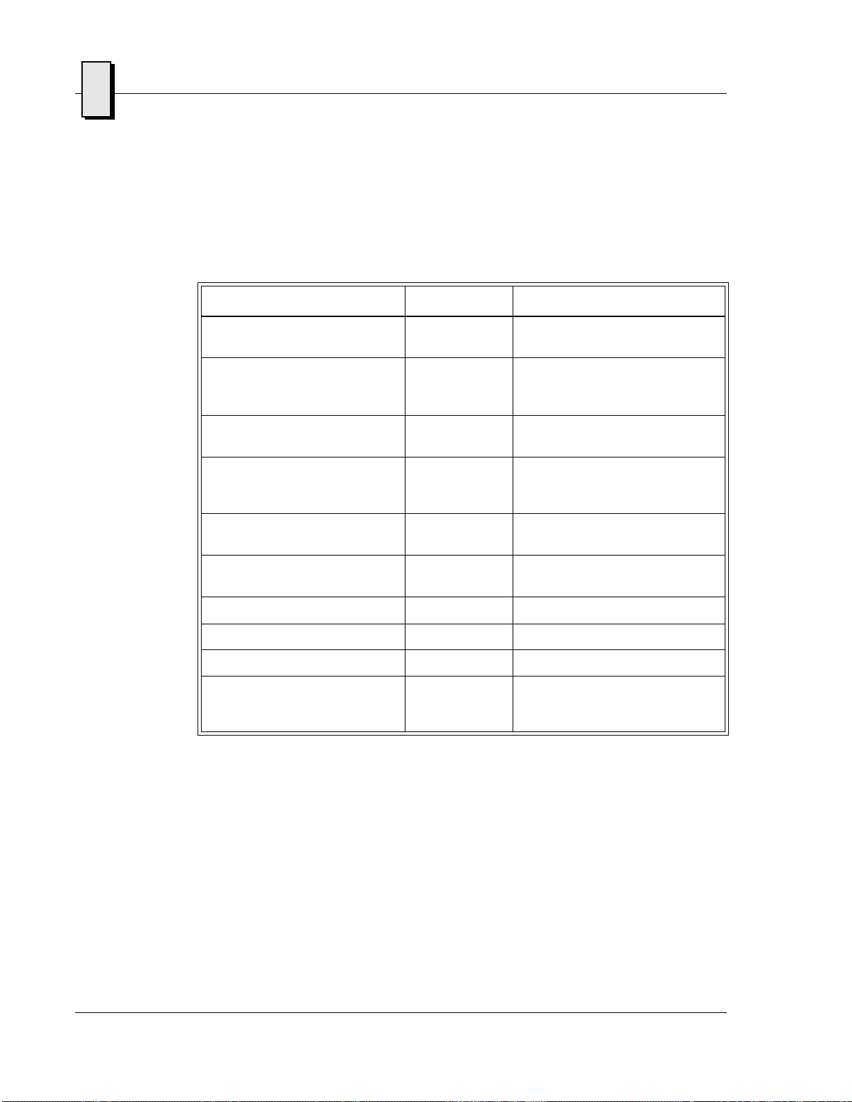
The VMIVME-7740 supports standard PC/AT I/O features such as those listed in
Table 1-1. Figure 1-1 on page 25 shows a block diagram of the VMIVM E-7740
emphasizing the I/O features including the PCI-to-VMEbus bridge.
Table 1-1 PC/AT I/O Features
I/O FEAT URE IDENTIFIER PHYSICAL ACCESS
Two Serial Ports
(16550-Compatible RS-232C)
AT-Style Keyboard/Mouse
Controller with a PS/2-Style
Adapter
Super VGA Video Controller
with 4 Mbyte SGRAM
Dual Ethernet, 10BaseT,
100BaseTx, No ve ll NE-2000
Compatible
Floppy Disk Controller
(two drives maximum)
Ultra IDE Fixed Disk Controller
(two drives maximum)
Hardware Reset RST Front Pane l Pus h-Button
IBM/PC Soun d Front Panel Speaker Port
USB Ports Front Panel
Power Status, Hard Drive
Activity, VMEbus SYSFAIL, and
Ethernet Status
COM1
COM2
M/K Front Panel PS/2-Style Connector,
SVGA Front Panel DB15HD
LAN1
LAN2
Drives A, B P2
Drives C, D P2
LED Indicators Front Panel
Front Panel,
Dual Micro-D 9-Pin
Mini-DIN Circular (female)
Adapter “Y” Cable Supplie d
High Density (female)
Front Panel RJ45
24
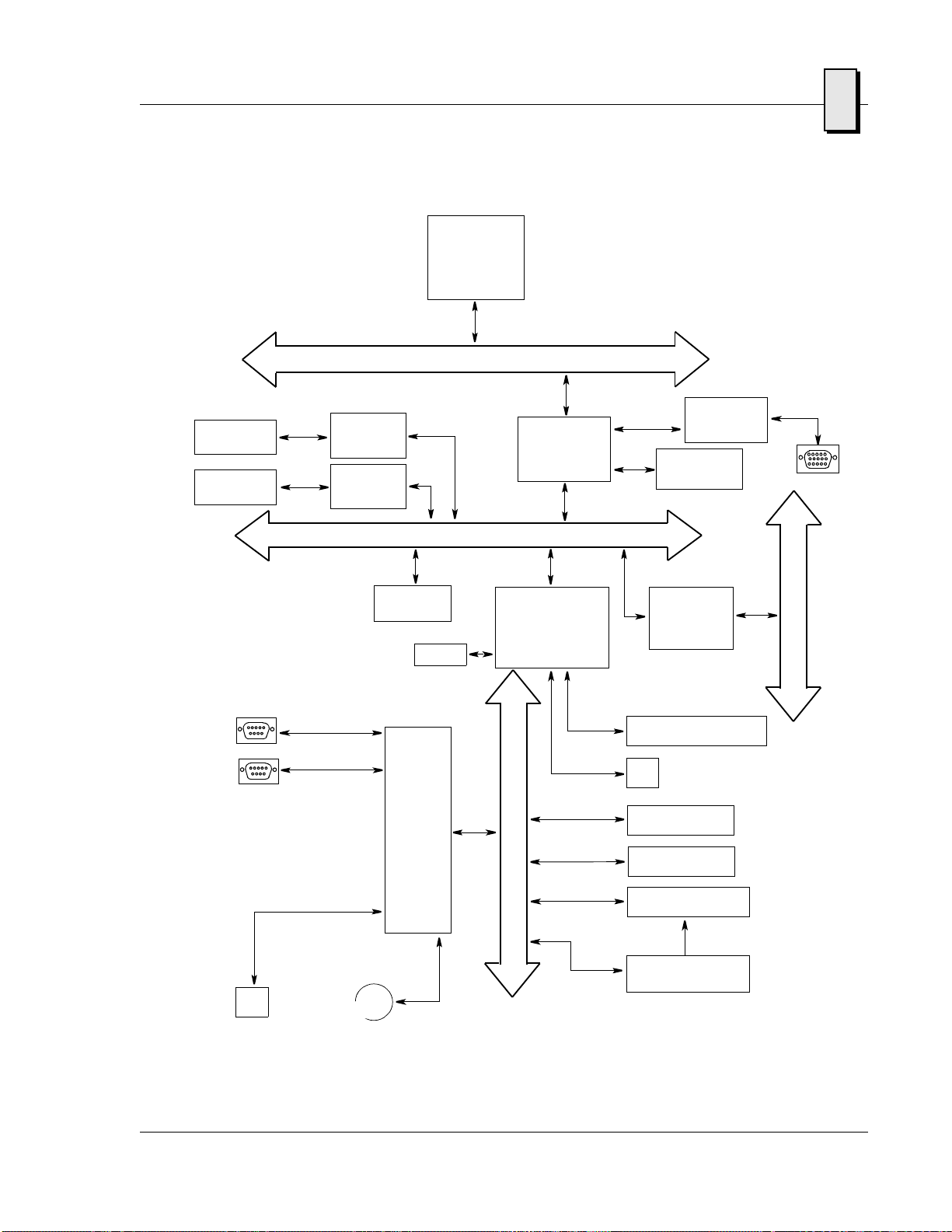
Pentium III
StockCheck.com
Processor
256k of Advanced
Transfer Cache
Host bus
1
10BaseT
100BaseTx
10BaseT
100BaseTx
COM Port 1
COM Port 2
Floppy Drive
Ethernet
Controller
Intel 82559
Ethernet
Controller
Intel 82559
PMC Site
USB
SUPER
I/O
with
RTC
SMC
FDC37C67X
PCI bus
South Bridge
North Bridge
System
Controller
82443GX
PCI-to-ISA, IDE
Accelerator
(PIIX4E)
EIDE
Hard
Drive
I
S
A
b
u
s
AGP
Graphics
C&T 69030
SDRAM
PCI-to-VME
Bridge
Universe IIB
CF Socket P7
P2
Flash BIOS
16-bit Timers
32 Kbyte NVRAM
SVGA
V
M
E
b
u
s
Watchdog Timer
NVRAM Controller DS1384
P2
PS/2 Keyboard/Mouse
Figure 1-1 VMIVME-7740 Block Diagram
25

1
StockCheck.com
VMIVME-7740 Product Manual
VMEbus Features
In addition to its PC/AT functions, the VMIVME-7740 has the following VMEbus
features:
• Single-slot, 6U height VMEbus board
• Complete six-line Address Modifier (AM-Code) programmability
• VME data interface with separate hardware byte/word swapping for master
• Support for VME64 multiplexed MBLT 64-bit VMEbus block transfers
• User-configured interrupter
• User-configured interrupt handler
• System Controller mode with programmable VMEbus arbiter
• VMEbus BERR bus error timer (software programmable)
• S lave a ccess from the VMEbus to local RAM and mailbox registers
• Full-featured programmable VMEbus requester
• System Controller autodetection
• Complete VMEbus m aster access through five separate Protected-mode
and slave accesses
(PRI, SGL, and RRS modes are supported)
(ROR, RWD, and BCAP modes are supported)
memory windows
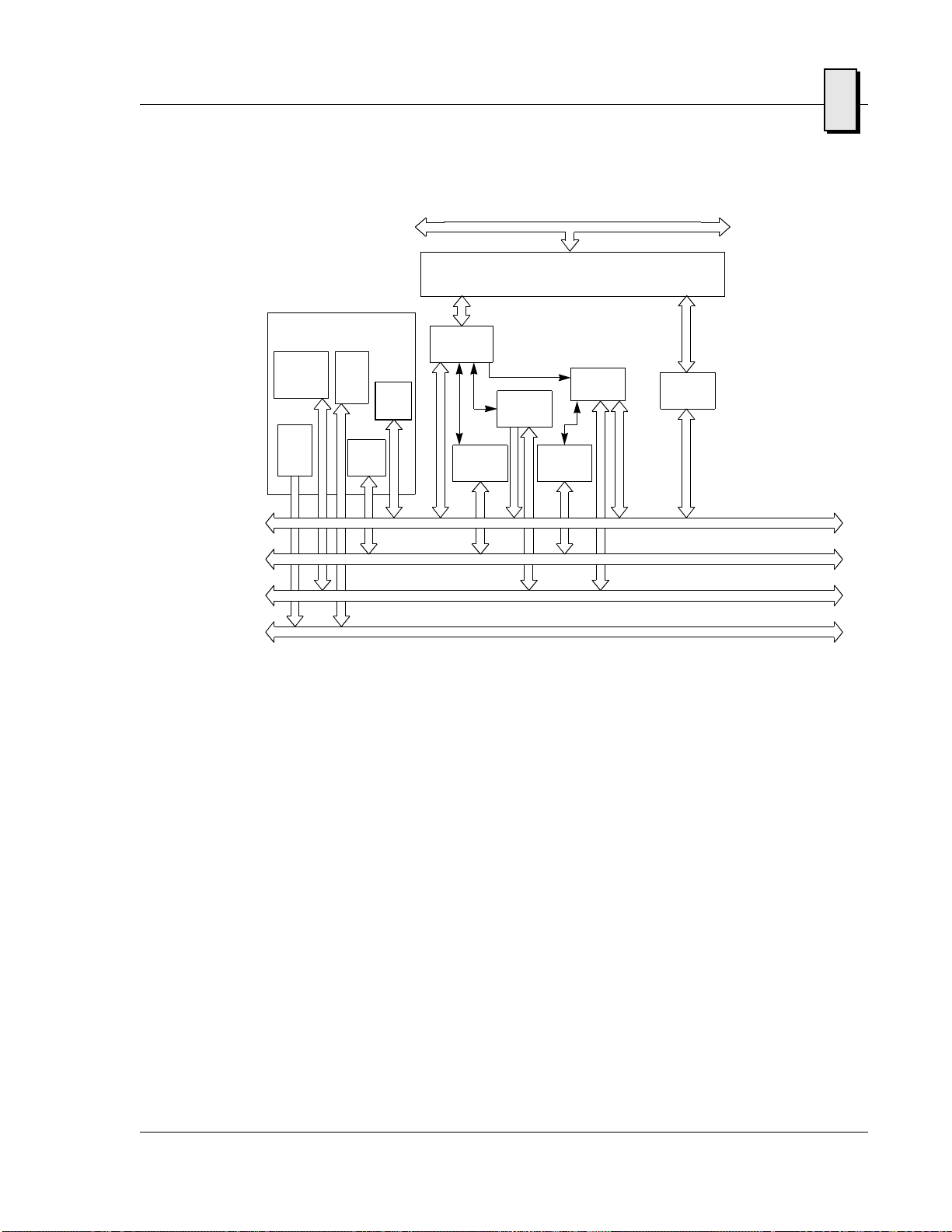
Figure 1-2 illustrates the VMIVME-7740 func tions in a typical VMEbus system. The
VMIVME-7740 is a versatile single-board solution fo r VMEbus control with familiar
PC/AT operation.
The VMIVME-7740 VMEbus interface is provided by the PCI-to-VMEbus bridge built
around the Tundra Semiconductor Corporation Universe II VMEbus interface chip.
The Universe II provides a reliable high-performance 64-bit VMEbus-to-PCI interface
in one design. The functions and programming of the Universe-based VMEbus
interface are addressed in detail in a separate associated manual titled: VMIVME-7740
Tundra Universe II Based VMEbus Interface Product Manual (500-657740-001).
26
StockCheck.com
VMIVME-7740
Slot 1 System Controller
Intrpt Ack
Daisy-Chain
Driver
16 MHz
Clock
Driver
System
Reset
Driver
DTB
Arbiter
Bus
Timer
(Program-
mable)
DTB
Master
DTB
Requester
PCI bus
PCI-to-VMEbus Bridge
Interrupt
Interrupter
Stat/ID IQx
Handler
DTB
Requester
DTB
Slave
VMEbus Features
Data Transfer Bus
DTB Arbitration
1
VMIVME-7740 Product Options
VMIC’s VMIVME-7740 is built around three fundamental hardware configurations.
These involve processor performance, the Flash Disk, and SDRAM memory size.
These options are subject to change based on emerging technologies and availability of vendor
configurations.
The options and current details available with the VMIVME-7740 are defined in the
device specification sheet available from your VMIC representative.
Priority Interrupt
Utility
Figure 1-2 VMIVME-7740 VMEbus Functions
27

1
StockCheck.com
VMIVME-7740 Product Manual
28

Installation and Setup
StockCheck.com
Contents
Unpacking Procedures. . . . . . . . . . . . . . . . . . . . . . . . . . . . . . . . . . . . . . . . . . . . . . . 29
Hardware Setup . . . . . . . . . . . . . . . . . . . . . . . . . . . . . . . . . . . . . . . . . . . . . . . . . . . . 30
Installation . . . . . . . . . . . . . . . . . . . . . . . . . . . . . . . . . . . . . . . . . . . . . . . . . . . . . . . . . 35
CHAPTER
2
Introduction
This chapter describes the hardware jumper settings, connector definitions,
installation, system setup, and operation of the VMIVME-7740. The PCI-to-VMEbus
bridge and the Tundra Universe II-based interface are also included.
Unpacking Procedures
Any precautions found in the shipping container should be observed. All items
should be carefully unpacked and thoroughly inspected for damage that might have
occurred during shipment. All claims arising from shipping damage should be filed
with the carrier and a complete report sent to VMIC Customer Service together with a
request for advice concerning the disposition of the damaged item(s).
CAUTION: Some of the components assembled on VMIC’s products may be sensitive
to electrostatic discharge, and damage may occur on boards that are subjected to a
high energy electrostatic field. When the board is placed on a bench for configuring,
etc., it is suggested that conductive material be inserted under the board to provide a
conductive shunt. Unused boards should be stored in the same protective boxes in
which they were shipped.
29

2
StockCheck.com
VMIVME-7740 Product Manual
Hardware Setup
The VMIVME-7740 is factory populated with user-specified options as part of the
VMIVME-7740 ordering information. The CPU speed, SDRAM, and flash size are not
user-upgradable. To change these options contact customer service to receive a R eturn
Material Authorization (RMA).
VMIC Customer Service is available at: 1-800-240-7782.
Or E-mail us at customer.service@vmic.com
The VMIVME-7740 is tested for system operation and shipped with factory-installed
header jumpers. The physical location of the jumpers and connectors for the single
board CPU are illustrated in Figure 2-1 on page 31. The definitions of the CPU board
jumpers and connectors are included in Table 2-1 through Table 2-4.
CAUTION: All jumpers are factory configured and should not be modified by the
user. There are three exceptions: the Password Clear (E4), the Programmable Timer
Clock Select (E8), the Watchdog Timer (E8) and the NVRAM Battery Power (E8).
Modifying any other jumper will void the Warranty and may damage the unit. The
default jumper condition of the VMIVME-7740 is expressed in Table 2-1 through
Table 2-6 with bold text in the table cells.
30
 Loading...