

VMIC VMIVME-7697 Product Manual

Artisan Technology Group is your source for quality
new and certied-used/pre-owned equipment
• FAST SHIPPING AND
DELIVERY
• TENS OF THOUSANDS OF
IN-STOCK ITEMS
• EQUIPMENT DEMOS
• HUNDREDS OF
MANUFACTURERS
SUPPORTED
• LEASING/MONTHLY
RENTALS
• ITAR CERTIFIED
SECURE ASSET SOLUTIONS
SERVICE CENTER REPAIRS
Experienced engineers and technicians on staff
at our full-service, in-house repair center
Instra
Remotely inspect equipment before purchasing with
our interactive website at www.instraview.com
Contact us: (888) 88-SOURCE | sales@artisantg.com | www.artisantg.com
SM
REMOTE INSPECTION
View
WE BUY USED EQUIPMENT
Sell your excess, underutilized, and idle used equipment
We also offer credit for buy-backs and trade-ins
www.artisantg.com/WeBuyEquipment
LOOKING FOR MORE INFORMATION?
Visit us on the web at www.artisantg.com for more
information on price quotations, drivers, technical
specications, manuals, and documentation

VMIVME-7697
Pentium III® Processor-Based VMEbus CPU
Product Manual
12090 South Memorial Parkway
Huntsville, Alabama 35803-3308, USA
(256) 880-0444
Artisan Technology Group - Quality Instrumentation ... Guaranteed | (888) 88-SOURCE | www.artisantg.com
w (800) 322-3616 w Fax: (256) 882-0859
500-007697-000 Rev. B
7-Feb-2000

12090 South Memorial Parkway
Huntsville, Alabama 35803-3308, USA
(256) 880-0444
Artisan Technology Group - Quality Instrumentation ... Guaranteed | (888) 88-SOURCE | www.artisantg.com
w (800) 322-3616 w Fax: (256) 882-0859

COPYRIGHT AND TRADEMARKS
© Copyright 1999. The information in this document has been carefully checked and is believed to be entirely reliable.
While all reasonable efforts to ensure accuracy have been taken in the preparation of this manual, VMIC assumes no
responsibility resulting from omissions or errors in this manual, or from the use of information contained herein.
VMIC reserves the right to make any changes, without notice, to this or any of VMIC’s products to improve reliability,
performance, function, or design.
VMIC does not assume any liability arising out of the application or use of any product or circuit described herein; nor
does VMIC convey any license under its patent rights or the rights of others.
For warranty and repair policies, refer to VMIC’s Standard Conditions of Sale.
AMXbus, BITMODULE, COSMODULE, DMAbus, Instant OPC wizard logo, IOWorks Access, IOWorks Foundation,
IOWorks man figure, IOWorks Manager, IOWorks Server, MAGICWARE, MEGAMODULE, PLC ACCELERATOR
(ACCELERATION), Quick Link, RTnet, Soft Logic Link, SRTbus, TESTCAL, “The Next Generation PLC”, The PLC
Connection, TURBOMODULE, UCLIO, UIOD, UPLC, Visual Soft Logic Control(ler),
VMEmonitor
Logic Experts, and The Total Solutions Provider are service marks of VMIC.
, VMEnet, VMEnet II, and
VMEprobe
are trademarks. The I/O Experts, The I/O Systems Experts, The Soft
VMEaccess, VMEmanager
,
(I/O man figure)
The I/O man figure, IOWorks, UIOC, Visual IOWorks, and
ActiveX is a trademark and Microsoft, Microsoft Access, MS-DOS, Visual Basic, Visual C++, Win32, Windows,
Windows NT, and XENIX are registered trademarks of Microsoft Corporation.
MMX is a trademark and Pentium is a registered trademark of Intel Corporation.
PICMG and CompactPCI are registered trademarks of PCI Industrial Computer Manufacturers’ Group.
Other registered trademarks are the property of their respective owners.
WinUIOC
(IOWorks man figure)(Instant OPC wizard logo)
are registered trademarks of VMIC.
VMIC
All Rights Reserved
This document shall not be duplicated, nor its contents used for any
purpose, unless granted express written permission from VMIC.
Artisan Technology Group - Quality Instrumentation ... Guaranteed | (888) 88-SOURCE | www.artisantg.com

12090 South Memorial Parkway
Huntsville, Alabama 35803-3308, USA
(256) 880-0444
Artisan Technology Group - Quality Instrumentation ... Guaranteed | (888) 88-SOURCE | www.artisantg.com
w (800) 322-3616 w Fax: (256) 882-0859

Table of Contents
Chapter 1 - Overview
Organization of the Manual
References
Safety Summary
Safety Symbols Used in This Manual
Notation and Terminology
. . . . . . . . . . . . . . . . . . . . . . . . . . . . . . . . . . . . . . . . . . . . . . . . . . . . . . . . . . . . . . . . . . . . . . . . . . . . . . . . 19
. . . . . . . . . . . . . . . . . . . . . . . . . . . . . . . . . . . . . . . . . . . . . . . . . . . . . . . . . . . . . . . . . . . . . . 17
. . . . . . . . . . . . . . . . . . . . . . . . . . . . . . . . . . . . . . . . . . . . . . . . . . . . . . . . . . . . . . . . . 18
. . . . . . . . . . . . . . . . . . . . . . . . . . . . . . . . . . . . . . . . . . . . . . . . . . . . . . . . . . . . . . . . . . . . . . . . . . . 21
. . . . . . . . . . . . . . . . . . . . . . . . . . . . . . . . . . . . . . . . . . . . . . . . . . . . . . . . 22
. . . . . . . . . . . . . . . . . . . . . . . . . . . . . . . . . . . . . . . . . . . . . . . . . . . . . . . . . . . . . . . . . . 23
Chapter 2 - VMIVME-7697 Features and Options
VMEbus Features
VMIVME-7697 Product Options
Chapter 3 - Installation and Setup
Unpacking Procedures
Hardware Setup
Installation
BIOS Setup
Front Panel Connectors
PMC Expansion Site Connectors
LED Definition
. . . . . . . . . . . . . . . . . . . . . . . . . . . . . . . . . . . . . . . . . . . . . . . . . . . . . . . . . . . . . . . . . . . . . . . . . . . . . . . . . 40
. . . . . . . . . . . . . . . . . . . . . . . . . . . . . . . . . . . . . . . . . . . . . . . . . . . . . . . . . . . . . . . . . . . . . . . . . . 28
. . . . . . . . . . . . . . . . . . . . . . . . . . . . . . . . . . . . . . . . . . . . . . . . . . . . . . . . . 29
. . . . . . . . . . . . . . . . . . . . . . . . . . . . . . . . . . . . . . . . . . . . . . . . . . . . . 31
. . . . . . . . . . . . . . . . . . . . . . . . . . . . . . . . . . . . . . . . . . . . . . . . . . . . . . . . . . . . . . . . . . . . . 31
. . . . . . . . . . . . . . . . . . . . . . . . . . . . . . . . . . . . . . . . . . . . . . . . . . . . . . . . . . . . . . . . . . . . . . . . . . . . 32
. . . . . . . . . . . . . . . . . . . . . . . . . . . . . . . . . . . . . . . . . . . . . . . . . . . . . . . . . . . . . . . . . . . . . . . . . . . . 41
. . . . . . . . . . . . . . . . . . . . . . . . . . . . . . . . . . . . . . . . . . . . . . . . . . . . . . . . . . . . . . . . 41
. . . . . . . . . . . . . . . . . . . . . . . . . . . . . . . . . . . . . . . . . . . . . . . . . . . . . . . . 41
. . . . . . . . . . . . . . . . . . . . . . . . . . . . . . . . . . . . . . . . . . . . . . . . . . . . . . . . . . . . . . . . . . . . . . . . . . 42
. . . . . . . . . . . . . . . . . . . . . . . . . . . . . . . . . . . . 25
Chapter 4 - PC/AT Functions
CPU Socket
Physical Memory
Memory and Port Maps
Memory Map - Tundra Universe II-Based PCI-to-VMEbus Bridge
I/O Port Map
PC/AT Interrupts
Artisan Technology Group - Quality Instrumentation ... Guaranteed | (888) 88-SOURCE | www.artisantg.com
. . . . . . . . . . . . . . . . . . . . . . . . . . . . . . . . . . . . . . . . . . . . . . . . . . . . . . . . . . . . . . . . . . . . . . . . . . . . . . . . 44
. . . . . . . . . . . . . . . . . . . . . . . . . . . . . . . . . . . . . . . . . . . . . . . . . . . . . . . . . . . . . . . . . . . . . . . . . . . 44
. . . . . . . . . . . . . . . . . . . . . . . . . . . . . . . . . . . . . . . . . . . . . . . . . . . . . . . . . . . . . . . . . . . . . 45
. . . . . . . . . . . . . . . . . . . . . . . . . . . . . . . . . . . . . . . . . . . . . . . . . . . . . . . . . . . . . . . . . . . . . . . . . . . 46
. . . . . . . . . . . . . . . . . . . . . . . . . . . . . . . . . . . . . . . . . . . . . . . . . . . . . . . . . . . . . . . . . . . . . . . . . . . 48
. . . . . . . . . . . . . . . . . . . . . . . . . . . . . . . . . . . . . . . . . . . . . . . . . . . . . . . . . . . . 43
. . . . . . . . . . . . . . . . . . . . . . . . . 45
5

VMIVME-7697 Product Manual
PCI Interrupts
I/O Ports
Video Graphics Adapter
Ethernet Controller
10BaseT
100BaseTx
Universal Serial Bus
SCSI Controller
. . . . . . . . . . . . . . . . . . . . . . . . . . . . . . . . . . . . . . . . . . . . . . . . . . . . . . . . . . . . . . . . . . . . . . . . . . . . . . 52
. . . . . . . . . . . . . . . . . . . . . . . . . . . . . . . . . . . . . . . . . . . . . . . . . . . . . . . . . . . . . . . . . . . . . . . . . . . . . . . . . . . 53
. . . . . . . . . . . . . . . . . . . . . . . . . . . . . . . . . . . . . . . . . . . . . . . . . . . . . . . . . . . . . . . . . . . . 55
. . . . . . . . . . . . . . . . . . . . . . . . . . . . . . . . . . . . . . . . . . . . . . . . . . . . . . . . . . . . . . . . . . . . . . . . . 56
. . . . . . . . . . . . . . . . . . . . . . . . . . . . . . . . . . . . . . . . . . . . . . . . . . . . . . . . . . . . . . . . . . . . . . . . . . . . . . . 56
. . . . . . . . . . . . . . . . . . . . . . . . . . . . . . . . . . . . . . . . . . . . . . . . . . . . . . . . . . . . . . . . . . . . . . . . . . . . 56
. . . . . . . . . . . . . . . . . . . . . . . . . . . . . . . . . . . . . . . . . . . . . . . . . . . . . . . . . . . . . . . . . . . . . . . . 57
. . . . . . . . . . . . . . . . . . . . . . . . . . . . . . . . . . . . . . . . . . . . . . . . . . . . . . . . . . . . . . . . . . . . . . . . . . . . 57
Chapter 5 - Embedded PC/RTOS Features
Timers
Timer Control Registers
Watchdog Timer
Battery Backed SRAM
Flash Disk
. . . . . . . . . . . . . . . . . . . . . . . . . . . . . . . . . . . . . . . . . . . . . . . . . . . . . . . . . . . . . . . . . . . . . . . . . . . . . . . . . . . . . 60
Timer Structure
Timer Functionality
Polling
Timer Status
Timer Read-Back
Programming
Time of Day Registers
Time of Day Alarm Registers
Watchdog Alarm Registers
Command Register
Watchdog Output Routing Register
Configuration
Functionality
Advanced Configuration
. . . . . . . . . . . . . . . . . . . . . . . . . . . . . . . . . . . . . . . . . . . . . . . . . . . . . . . . . . . . . . . . . . . . . . . . . . . . . . . . . 64
Timer Width Control/System State (TWSS) Register, Offset 30h
Timer Enable/Interrupt (TEI) Register: Offset 34h
Timer Interrupt Status (TIS) Register, Offset 38h
. . . . . . . . . . . . . . . . . . . . . . . . . . . . . . . . . . . . . . . . . . . . . . . . . . . . . . . . . . . . . . . . . . . . . . . . . . . . . . . . . 81
. . . . . . . . . . . . . . . . . . . . . . . . . . . . . . . . . . . . . . . . . . . . . . . . . . . . . . . . . . . . . . . . . . . . . . . . 60
. . . . . . . . . . . . . . . . . . . . . . . . . . . . . . . . . . . . . . . . . . . . . . . . . . . . . . . . . . . . . . . . . . . . . 61
. . . . . . . . . . . . . . . . . . . . . . . . . . . . . . . . . . . . . . . . . . . . . . . . . . . . . . . . . . . . . . . . . . . . . . . . . . . 65
. . . . . . . . . . . . . . . . . . . . . . . . . . . . . . . . . . . . . . . . . . . . . . . . . . . . . . . . . . . . . . . . . . . . . . 66
. . . . . . . . . . . . . . . . . . . . . . . . . . . . . . . . . . . . . . . . . . . . . . . . . . . . . . . . . . . . . . . . . . . . 68
. . . . . . . . . . . . . . . . . . . . . . . . . . . . . . . . . . . . . . . . . . . . . . . . . . . . . . . . . . . . . . . . . . . . . . . . . . 68
. . . . . . . . . . . . . . . . . . . . . . . . . . . . . . . . . . . . . . . . . . . . . . . . . . . . . . . . . . . . . . . . . . . . . . . . . . . 74
. . . . . . . . . . . . . . . . . . . . . . . . . . . . . . . . . . . . . . . . . . . . . . . . . . . . . . . . . . . . . . . . . . 76
. . . . . . . . . . . . . . . . . . . . . . . . . . . . . . . . . . . . . . . . . . . . . . . . . . . . . . . . . . . . 77
. . . . . . . . . . . . . . . . . . . . . . . . . . . . . . . . . . . . . . . . . . . . . . . . . . . . . . . . . . . . . 78
. . . . . . . . . . . . . . . . . . . . . . . . . . . . . . . . . . . . . . . . . . . . . . . . . . . . . . . . . . . . . . . . . . . . . 78
. . . . . . . . . . . . . . . . . . . . . . . . . . . . . . . . . . . . . . . . . . . . . . . . . . . . . . 79
. . . . . . . . . . . . . . . . . . . . . . . . . . . . . . . . . . . . . . . . . . . . . . . . . . . . . . . . . . . . . . . . . . . . . . 80
. . . . . . . . . . . . . . . . . . . . . . . . . . . . . . . . . . . . . . . . . . . . . . . . . . . . . . . . . . . . . . . . . . . . . . . . . . 81
. . . . . . . . . . . . . . . . . . . . . . . . . . . . . . . . . . . . . . . . . . . . . . . . . . . . . . . . . . . . . . . . . . . . . . . . . . . 82
. . . . . . . . . . . . . . . . . . . . . . . . . . . . . . . . . . . . . . . . . . . . . . . . . . . . . . . . . . . . . . . . 82
. . . . . . . . . . . . . . . . . . . . . . . . . . . . . . . . . . . . . . . . . . . 59
. . . . . . . . . . . . . . . . . . . . . . 70
. . . . . . . . . . . . . . . . . . . . . . . . . . . . . . . . . . . . 72
. . . . . . . . . . . . . . . . . . . . . . . . . . . . . . . . . . . . . 73
Chapter 6 - Maintenance
Maintenance Prints
. . . . . . . . . . . . . . . . . . . . . . . . . . . . . . . . . . . . . . . . . . . . . . . . . . . . . . . . . . . . . . . . . . . . . . . . . 85
. . . . . . . . . . . . . . . . . . . . . . . . . . . . . . . . . . . . . . . . . . . . . . . . . . . . . . . . . . . . . . . . . 85
Appendix A - Connector Pinouts
Ethernet Connector Pinout
6
Artisan Technology Group - Quality Instrumentation ... Guaranteed | (888) 88-SOURCE | www.artisantg.com
. . . . . . . . . . . . . . . . . . . . . . . . . . . . . . . . . . . . . . . . . . . . . . . . . . . . . . . . . . . . . . . . . . 89
. . . . . . . . . . . . . . . . . . . . . . . . . . . . . . . . . . . . . . . . . . . . . . . . . . . . . . . 87

Table of Contents
Video Connector Pinout
Parallel Port Connector Pinout
Serial Connector Pinout
Keyboard Connector Pinout
Mouse Connector Pinout
VMEbus Connector Pinout
USB Connector
. . . . . . . . . . . . . . . . . . . . . . . . . . . . . . . . . . . . . . . . . . . . . . . . . . . . . . . . . . . . . . . . . . . . . . . . . . . . 99
. . . . . . . . . . . . . . . . . . . . . . . . . . . . . . . . . . . . . . . . . . . . . . . . . . . . . . . . . . . . . . . . . . . . 90
. . . . . . . . . . . . . . . . . . . . . . . . . . . . . . . . . . . . . . . . . . . . . . . . . . . . . . . . . . . . . . 91
. . . . . . . . . . . . . . . . . . . . . . . . . . . . . . . . . . . . . . . . . . . . . . . . . . . . . . . . . . . . . . . . . . . . 92
. . . . . . . . . . . . . . . . . . . . . . . . . . . . . . . . . . . . . . . . . . . . . . . . . . . . . . . . . . . . . . . . . 93
. . . . . . . . . . . . . . . . . . . . . . . . . . . . . . . . . . . . . . . . . . . . . . . . . . . . . . . . . . . . . . . . . . . 94
. . . . . . . . . . . . . . . . . . . . . . . . . . . . . . . . . . . . . . . . . . . . . . . . . . . . . . . . . . . . . . . . . . 95
Appendix B - System Driver Software
Driver Software Installation
Windows for Workgroups (Version 3.11)
Windows 95
SCSI Driver Installation Directions For Windows 95
Windows 95 INF Update Utility for Intel(TM) Chipsets
Bus Master IDE Driver for Windows 95
Windows NT (Version 4.0)
. . . . . . . . . . . . . . . . . . . . . . . . . . . . . . . . . . . . . . . . . . . . . . . . . . . . . . . . . . . . . . . . . . . . . . . . . . . . . . . . 104
Appendix C - Award - BIOS
System BIOS Setup Utility
Standard CMOS Setup
Setting The Date
Setting The Time
Primary Master/Slave
Secondary Master/Slave
Floppy Disk Drive
Floppy Drive A
Floppy Drive B
Video
Halt On
Memory
BIOS Features Setup
Virus Warning
CPU Internal Cache
Pentium III Serial Number
External Cache
CPU L2 Cache ECC Checking
Quick Power On Self Test
Boot From LAN First
. . . . . . . . . . . . . . . . . . . . . . . . . . . . . . . . . . . . . . . . . . . . . . . . . . . . . . . . . . . . . . . . . . . . . . . . . . . . . . . . . . 114
. . . . . . . . . . . . . . . . . . . . . . . . . . . . . . . . . . . . . . . . . . . . . . . . . . . . . . . . . . . . . . . . . . . . . . . . . . . . . . . . 114
. . . . . . . . . . . . . . . . . . . . . . . . . . . . . . . . . . . . . . . . . . . . . . . . . . . . . . . . . . . . . . . . . . . . . . . . . . . . . . . . 115
. . . . . . . . . . . . . . . . . . . . . . . . . . . . . . . . . . . . . . . . . . . . . . . . . . . . . . . . . . . . . . . . . . . . . . . . . . 116
. . . . . . . . . . . . . . . . . . . . . . . . . . . . . . . . . . . . . . . . . . . . . . . . . . . . . . . . . . . . . . . . . . . . . . . . . 117
. . . . . . . . . . . . . . . . . . . . . . . . . . . . . . . . . . . . . . . . . . . . . . . . . . . . . . . . . . . . . . . . . 101
. . . . . . . . . . . . . . . . . . . . . . . . . . . . . . . . . . . . . . . . . . . . . . . . . . . . . 102
. . . . . . . . . . . . . . . . . . . . . . . . . . . . . . . . . . . . . . . . . . . . . . . . . . . . . . . . . . . . . . . . . . 108
. . . . . . . . . . . . . . . . . . . . . . . . . . . . . . . . . . . . . . . . . . . . . . . . . . . . . . . . . . . . . . 111
. . . . . . . . . . . . . . . . . . . . . . . . . . . . . . . . . . . . . . . . . . . . . . . . . . . . . . . . . . . . . . . . . . 112
. . . . . . . . . . . . . . . . . . . . . . . . . . . . . . . . . . . . . . . . . . . . . . . . . . . . . . . . . . . . . . . . . . . . . 113
. . . . . . . . . . . . . . . . . . . . . . . . . . . . . . . . . . . . . . . . . . . . . . . . . . . . . . . . . . . . . . . . . . . . . . . 113
. . . . . . . . . . . . . . . . . . . . . . . . . . . . . . . . . . . . . . . . . . . . . . . . . . . . . . . . . . . . . . . . . . . . . . . 113
. . . . . . . . . . . . . . . . . . . . . . . . . . . . . . . . . . . . . . . . . . . . . . . . . . . . . . . . . . . . . . . . . . . 113
. . . . . . . . . . . . . . . . . . . . . . . . . . . . . . . . . . . . . . . . . . . . . . . . . . . . . . . . . . . . . . . . 114
. . . . . . . . . . . . . . . . . . . . . . . . . . . . . . . . . . . . . . . . . . . . . . . . . . . . . . . . . . . . . . . . . . . . . . 114
. . . . . . . . . . . . . . . . . . . . . . . . . . . . . . . . . . . . . . . . . . . . . . . . . . . . . . . . . . . . . . . . . . . . . 114
. . . . . . . . . . . . . . . . . . . . . . . . . . . . . . . . . . . . . . . . . . . . . . . . . . . . . . . . . . . . . . . . . . . . . 114
. . . . . . . . . . . . . . . . . . . . . . . . . . . . . . . . . . . . . . . . . . . . . . . . . . . . . . . . . . . . . . . . . . . . . . . 116
. . . . . . . . . . . . . . . . . . . . . . . . . . . . . . . . . . . . . . . . . . . . . . . . . . . . . . . . . . . . . . . . . . . . 116
. . . . . . . . . . . . . . . . . . . . . . . . . . . . . . . . . . . . . . . . . . . . . . . . . . . . . . . . . . . . . . . 117
. . . . . . . . . . . . . . . . . . . . . . . . . . . . . . . . . . . . . . . . . . . . . . . . . . . . . . . . . . 117
. . . . . . . . . . . . . . . . . . . . . . . . . . . . . . . . . . . . . . . . . . . . . . . . . . . . . . . . . . . . . . 117
. . . . . . . . . . . . . . . . . . . . . . . . . . . . . . . . . . . . . . . . . . . . . . . . . . . . . . . . . . . . . . . . . . . . 117
. . . . . . . . . . . . . . . . . . . . . . . . . . . . . . . . . . . . . . . . . . . . . . . . . 101
. . . . . . . . . . . . . . . . . . . . . . . . . . . . . . . . . . . . . . 105
. . . . . . . . . . . . . . . . . . . . . . . . . . . . . . . . . . . . 106
. . . . . . . . . . . . . . . . . . . . . . . . . . . . . . . . . . . . . . . . . . . . . . . . . . 106
Artisan Technology Group - Quality Instrumentation ... Guaranteed | (888) 88-SOURCE | www.artisantg.com
7

VMIVME-7697 Product Manual
Boot Sequence
Swap Floppy Drive
. . . . . . . . . . . . . . . . . . . . . . . . . . . . . . . . . . . . . . . . . . . . . . . . . . . . . . . . . . . . . . . . . . . . . . . . . 117
. . . . . . . . . . . . . . . . . . . . . . . . . . . . . . . . . . . . . . . . . . . . . . . . . . . . . . . . . . . . . . . . . . . . . 117
Boot Up Floppy Seek
Boot Up NumLock Status
Gate A20 Option
. . . . . . . . . . . . . . . . . . . . . . . . . . . . . . . . . . . . . . . . . . . . . . . . . . . . . . . . . . . . . . . . . . . . . . . 118
Typematic Rate Setting
Typematic Rate (Chars/Sec)
Typematic Delay (Mse c)
Security Option
. . . . . . . . . . . . . . . . . . . . . . . . . . . . . . . . . . . . . . . . . . . . . . . . . . . . . . . . . . . . . . . . . . . . . . . . . 118
PCI/VGA Palette Snoop
Assign IRQ for VGA
. . . . . . . . . . . . . . . . . . . . . . . . . . . . . . . . . . . . . . . . . . . . . . . . . . . . . . . . . . . . . . . . . . . . 118
OS Select For DRAM>64MB
HDD S.M.A.R.T. Capability
Report No FDD For WIN95
Chipset Features Setup
. . . . . . . . . . . . . . . . . . . . . . . . . . . . . . . . . . . . . . . . . . . . . . . . . . . . . . . . . . . . . . . . . . . . 120
Advanced Options
SDRAM(CAS Lat/RAS-to-CAS)
SDRAM RAS Precharge Tim e
SDRAM CAS Latency Time
SDRAM Precharge Control
DRAM Data Integrity Mode
System BIOS Cacheable
Video RAM Cacheable
8 Bit I/O Recovery Time
16 Bit I/O Recovery Time
Memory Hole at 15M-16M
Passive Release
Delayed Transaction
. . . . . . . . . . . . . . . . . . . . . . . . . . . . . . . . . . . . . . . . . . . . . . . . . . . . . . . . . . . . . . . . . . . . . . . 122
. . . . . . . . . . . . . . . . . . . . . . . . . . . . . . . . . . . . . . . . . . . . . . . . . . . . . . . . . . . . . . . . . . . 122
AGP Aperture Size (MB)
CPU Warning Temperature
CPU Shutdown
Power Management
ACPI Function
Power Management
PM Control by APM
Video Off Method
Video Off After
Modem Use IRQ
. . . . . . . . . . . . . . . . . . . . . . . . . . . . . . . . . . . . . . . . . . . . . . . . . . . . . . . . . . . . . . . . . . . . . . . . . 122
. . . . . . . . . . . . . . . . . . . . . . . . . . . . . . . . . . . . . . . . . . . . . . . . . . . . . . . . . . . . . . . . . . . . . . . . 123
. . . . . . . . . . . . . . . . . . . . . . . . . . . . . . . . . . . . . . . . . . . . . . . . . . . . . . . . . . . . . . . . . . . . . . . . . 123
. . . . . . . . . . . . . . . . . . . . . . . . . . . . . . . . . . . . . . . . . . . . . . . . . . . . . . . . . . . . . . . . . . . . 123
. . . . . . . . . . . . . . . . . . . . . . . . . . . . . . . . . . . . . . . . . . . . . . . . . . . . . . . . . . . . . . . . . . . . 124
. . . . . . . . . . . . . . . . . . . . . . . . . . . . . . . . . . . . . . . . . . . . . . . . . . . . . . . . . . . . . . . . . . . . . . 124
. . . . . . . . . . . . . . . . . . . . . . . . . . . . . . . . . . . . . . . . . . . . . . . . . . . . . . . . . . . . . . . . . . . . . . . . . 124
. . . . . . . . . . . . . . . . . . . . . . . . . . . . . . . . . . . . . . . . . . . . . . . . . . . . . . . . . . . . . . . . . . . . . . . 124
. . . . . . . . . . . . . . . . . . . . . . . . . . . . . . . . . . . . . . . . . . . . . . . . . . . . . . . . . . . . . . . . . . . 117
. . . . . . . . . . . . . . . . . . . . . . . . . . . . . . . . . . . . . . . . . . . . . . . . . . . . . . . . . . . . . . . 118
. . . . . . . . . . . . . . . . . . . . . . . . . . . . . . . . . . . . . . . . . . . . . . . . . . . . . . . . . . . . . . . . . 118
. . . . . . . . . . . . . . . . . . . . . . . . . . . . . . . . . . . . . . . . . . . . . . . . . . . . . . . . . . . . 118
. . . . . . . . . . . . . . . . . . . . . . . . . . . . . . . . . . . . . . . . . . . . . . . . . . . . . . . . . . . . . . . . 118
. . . . . . . . . . . . . . . . . . . . . . . . . . . . . . . . . . . . . . . . . . . . . . . . . . . . . . . . . . . . . . . . 118
. . . . . . . . . . . . . . . . . . . . . . . . . . . . . . . . . . . . . . . . . . . . . . . . . . . . . . . . . . . . 119
. . . . . . . . . . . . . . . . . . . . . . . . . . . . . . . . . . . . . . . . . . . . . . . . . . . . . . . . . . . . . 119
. . . . . . . . . . . . . . . . . . . . . . . . . . . . . . . . . . . . . . . . . . . . . . . . . . . . . . . . . . . . . 119
. . . . . . . . . . . . . . . . . . . . . . . . . . . . . . . . . . . . . . . . . . . . . . . . . . . . . . . . . . . . . . . . . . 120
. . . . . . . . . . . . . . . . . . . . . . . . . . . . . . . . . . . . . . . . . . . . . . . . . . . . . . . . . 120
. . . . . . . . . . . . . . . . . . . . . . . . . . . . . . . . . . . . . . . . . . . . . . . . . . . . . . . . . . 120
. . . . . . . . . . . . . . . . . . . . . . . . . . . . . . . . . . . . . . . . . . . . . . . . . . . . . . . . . . . . . 121
. . . . . . . . . . . . . . . . . . . . . . . . . . . . . . . . . . . . . . . . . . . . . . . . . . . . . . . . . . . . . 121
. . . . . . . . . . . . . . . . . . . . . . . . . . . . . . . . . . . . . . . . . . . . . . . . . . . . . . . . . . . . . 121
. . . . . . . . . . . . . . . . . . . . . . . . . . . . . . . . . . . . . . . . . . . . . . . . . . . . . . . . . . . . . . . 121
. . . . . . . . . . . . . . . . . . . . . . . . . . . . . . . . . . . . . . . . . . . . . . . . . . . . . . . . . . . . . . . . . 121
. . . . . . . . . . . . . . . . . . . . . . . . . . . . . . . . . . . . . . . . . . . . . . . . . . . . . . . . . . . . . . . . 121
. . . . . . . . . . . . . . . . . . . . . . . . . . . . . . . . . . . . . . . . . . . . . . . . . . . . . . . . . . . . . . . 121
. . . . . . . . . . . . . . . . . . . . . . . . . . . . . . . . . . . . . . . . . . . . . . . . . . . . . . . . . . . . . . 122
. . . . . . . . . . . . . . . . . . . . . . . . . . . . . . . . . . . . . . . . . . . . . . . . . . . . . . . . . . . . . . . . 122
. . . . . . . . . . . . . . . . . . . . . . . . . . . . . . . . . . . . . . . . . . . . . . . . . . . . . . . . . . . . . 122
8
Artisan Technology Group - Quality Instrumentation ... Guaranteed | (888) 88-SOURCE | www.artisantg.com

Table of Contents
Doze Mode
Standby Mode
Suspend Mode
HDD Power Down
Throttle Duty Cycle
VGA Active Monitor
Resume By Ring
Resume By Alarm
Wake Up On LAN
CPU Clock Throttle
IRQ 8 Break Suspend
. . . . . . . . . . . . . . . . . . . . . . . . . . . . . . . . . . . . . . . . . . . . . . . . . . . . . . . . . . . . . . . . . . . . . . . . . . . . 124
. . . . . . . . . . . . . . . . . . . . . . . . . . . . . . . . . . . . . . . . . . . . . . . . . . . . . . . . . . . . . . . . . . . . . . . . . 124
. . . . . . . . . . . . . . . . . . . . . . . . . . . . . . . . . . . . . . . . . . . . . . . . . . . . . . . . . . . . . . . . . . . . . . . . . 124
. . . . . . . . . . . . . . . . . . . . . . . . . . . . . . . . . . . . . . . . . . . . . . . . . . . . . . . . . . . . . . . . . . . . . . 124
. . . . . . . . . . . . . . . . . . . . . . . . . . . . . . . . . . . . . . . . . . . . . . . . . . . . . . . . . . . . . . . . . . . . . 125
. . . . . . . . . . . . . . . . . . . . . . . . . . . . . . . . . . . . . . . . . . . . . . . . . . . . . . . . . . . . . . . . . . . . . 125
. . . . . . . . . . . . . . . . . . . . . . . . . . . . . . . . . . . . . . . . . . . . . . . . . . . . . . . . . . . . . . . . . . . . . . . 125
. . . . . . . . . . . . . . . . . . . . . . . . . . . . . . . . . . . . . . . . . . . . . . . . . . . . . . . . . . . . . . . . . . . . . . 125
. . . . . . . . . . . . . . . . . . . . . . . . . . . . . . . . . . . . . . . . . . . . . . . . . . . . . . . . . . . . . . . . . . . . . . 125
. . . . . . . . . . . . . . . . . . . . . . . . . . . . . . . . . . . . . . . . . . . . . . . . . . . . . . . . . . . . . . . . . . . . . 125
. . . . . . . . . . . . . . . . . . . . . . . . . . . . . . . . . . . . . . . . . . . . . . . . . . . . . . . . . . . . . . . . . . 125
Reload Global Timer Events
PnP/PCI Configuration
PNP OS Installed
Resources Controlled By
Reset Configuration Data
IRQ n Assigned to
DMA n Assigned to
Used Mem Base Addr
Integrated Peripherals
IDE HDD Block Mode
. . . . . . . . . . . . . . . . . . . . . . . . . . . . . . . . . . . . . . . . . . . . . . . . . . . . . . . . . . . . . . . . . . . . . . 126
. . . . . . . . . . . . . . . . . . . . . . . . . . . . . . . . . . . . . . . . . . . . . . . . . . . . . . . . . . . . . . . . . . . . . . . 126
. . . . . . . . . . . . . . . . . . . . . . . . . . . . . . . . . . . . . . . . . . . . . . . . . . . . . . . . . . . . . . . 126
. . . . . . . . . . . . . . . . . . . . . . . . . . . . . . . . . . . . . . . . . . . . . . . . . . . . . . . . . . . . . . . 126
. . . . . . . . . . . . . . . . . . . . . . . . . . . . . . . . . . . . . . . . . . . . . . . . . . . . . . . . . . . . . . . . . . . . . . 127
. . . . . . . . . . . . . . . . . . . . . . . . . . . . . . . . . . . . . . . . . . . . . . . . . . . . . . . . . . . . . . . . . . . . . 127
. . . . . . . . . . . . . . . . . . . . . . . . . . . . . . . . . . . . . . . . . . . . . . . . . . . . . . . . . . . . . . . . . . 127
. . . . . . . . . . . . . . . . . . . . . . . . . . . . . . . . . . . . . . . . . . . . . . . . . . . . . . . . . . . . . . . . . . . . . . 128
. . . . . . . . . . . . . . . . . . . . . . . . . . . . . . . . . . . . . . . . . . . . . . . . . . . . . . . . . . . . . . . . . . . 128
IDE Primary/Secondary Master PIO
IDE Primary/Secondary Slave PIO
IDE Primary/Secondary Master UDMA
IDE Primary/Secondary Slave UDMA
On-Chip Primary PCI IDE
. . . . . . . . . . . . . . . . . . . . . . . . . . . . . . . . . . . . . . . . . . . . . . . . . . . . . . . . . . . . . . . 129
On-Chip Secondary PCI IDE
Onboard PCI SCSI Chip
USB Keyboard Support
Init Display First
. . . . . . . . . . . . . . . . . . . . . . . . . . . . . . . . . . . . . . . . . . . . . . . . . . . . . . . . . . . . . . . . . . . . . . . . 129
Onboard FDC Controller
Onboard Serial Port 1/2
UART 2 Mode
. . . . . . . . . . . . . . . . . . . . . . . . . . . . . . . . . . . . . . . . . . . . . . . . . . . . . . . . . . . . . . . . . . . . . . . . . . 130
Onboard Parallel Port
Parallel Port Mode
. . . . . . . . . . . . . . . . . . . . . . . . . . . . . . . . . . . . . . . . . . . . . . . . . . . . . . . . . . . . . . . . 129
. . . . . . . . . . . . . . . . . . . . . . . . . . . . . . . . . . . . . . . . . . . . . . . . . . . . . . . . . . . . . . . . . 129
. . . . . . . . . . . . . . . . . . . . . . . . . . . . . . . . . . . . . . . . . . . . . . . . . . . . . . . . . . . . . . . . 129
. . . . . . . . . . . . . . . . . . . . . . . . . . . . . . . . . . . . . . . . . . . . . . . . . . . . . . . . . . . . . . . . . 130
. . . . . . . . . . . . . . . . . . . . . . . . . . . . . . . . . . . . . . . . . . . . . . . . . . . . . . . . . . . . . . . . . . . 130
. . . . . . . . . . . . . . . . . . . . . . . . . . . . . . . . . . . . . . . . . . . . . . . . . . . . . . . . . . . . . . . . . . . . . . 130
. . . . . . . . . . . . . . . . . . . . . . . . . . . . . . . . . . . . . . . . . . . . . . . . . . . . . . . . . . . . 125
. . . . . . . . . . . . . . . . . . . . . . . . . . . . . . . . . . . . . . . . . . . . . . . . . . . . . 128
. . . . . . . . . . . . . . . . . . . . . . . . . . . . . . . . . . . . . . . . . . . . . . . . . . . . . . 128
. . . . . . . . . . . . . . . . . . . . . . . . . . . . . . . . . . . . . . . . . . . . . . . . . . 129
. . . . . . . . . . . . . . . . . . . . . . . . . . . . . . . . . . . . . . . . . . . . . . . . . . . . 129
. . . . . . . . . . . . . . . . . . . . . . . . . . . . . . . . . . . . . . . . . . . . . . . . . . . . . . . . . . . . 129
Appendix D - LANWorks BIOS
System BIOS Setup Utility
Artisan Technology Group - Quality Instrumentation ... Guaranteed | (888) 88-SOURCE | www.artisantg.com
. . . . . . . . . . . . . . . . . . . . . . . . . . . . . . . . . . . . . . . . . . . . . . . . . . . . . . . . . . . . . . . . . . 132
. . . . . . . . . . . . . . . . . . . . . . . . . . . . . . . . . . . . . . . . . . . . . . . . . . . . . . . . . . 131
9

VMIVME-7697 Product Manual
BIOS Features Setup
LANWorks BIOS Setup
Boot Protocol
Default Boot
Local Boot
. . . . . . . . . . . . . . . . . . . . . . . . . . . . . . . . . . . . . . . . . . . . . . . . . . . . . . . . . . . . . . . . . . . . . . . 133
. . . . . . . . . . . . . . . . . . . . . . . . . . . . . . . . . . . . . . . . . . . . . . . . . . . . . . . . . . . . . . . . . . . . . 134
. . . . . . . . . . . . . . . . . . . . . . . . . . . . . . . . . . . . . . . . . . . . . . . . . . . . . . . . . . . . . . . . . . . . . . . . . . 134
. . . . . . . . . . . . . . . . . . . . . . . . . . . . . . . . . . . . . . . . . . . . . . . . . . . . . . . . . . . . . . . . . . . . . . . . . . . 134
. . . . . . . . . . . . . . . . . . . . . . . . . . . . . . . . . . . . . . . . . . . . . . . . . . . . . . . . . . . . . . . . . . . . . . . . . . . . . 134
Appendix E - SCSI Selection Utility
Configure/View Host Adapter Settings
SCSI Bus Interface Definitions
Host Adapter SCSI ID
SCSI Parity Checking
Host Adapter SCSI Termination
Additional Options
Boot Device Options
SCSI Device Configuration
Initiate Sync Negotiation
Maximum Synchronous Transfer Rate
Enable Disconnection
Initiate Wide Negotiation
Send Start Unit Command
Advanced Configuration Options
Host Adapter BIOS
Support Removable Disks Under BIOS as Fixed Disks
Extended BIOS Translation for DOS Drives > 1 Gbyte
Display <Ctrl-A> Message During BIOS Initialization
Multiple LUN Support
Support For Ultra SCSI Speed
SCSI Disk Utilities
Select SCSI Disk
Formatting a Disk
Verifying a Disk
. . . . . . . . . . . . . . . . . . . . . . . . . . . . . . . . . . . . . . . . . . . . . . . . . . . . . . . . . . . . . . . . . . . . . . . . . . 139
. . . . . . . . . . . . . . . . . . . . . . . . . . . . . . . . . . . . . . . . . . . . . . . . . . . . . . . . . . . . . . . . . . . . . 142
. . . . . . . . . . . . . . . . . . . . . . . . . . . . . . . . . . . . . . . . . . . . . . . . . . . . . . . . . . . . . . . . . . . . . . . . . . 144
. . . . . . . . . . . . . . . . . . . . . . . . . . . . . . . . . . . . . . . . . . . . . . . . . . . . . . . . . . . . . . . . . . . . . . . 144
. . . . . . . . . . . . . . . . . . . . . . . . . . . . . . . . . . . . . . . . . . . . . . . . . . . . . . . . . . . . . . . . . . . . . . 145
. . . . . . . . . . . . . . . . . . . . . . . . . . . . . . . . . . . . . . . . . . . . . . . . . . . . . . . . . . . . . . . . . . . . . . . . 145
. . . . . . . . . . . . . . . . . . . . . . . . . . . . . . . . . . . . . . . . . . . . . . . . . . . . . . . . . . . . . . 138
. . . . . . . . . . . . . . . . . . . . . . . . . . . . . . . . . . . . . . . . . . . . . . . . . . . . . . . . . . . . . . . . . . 138
. . . . . . . . . . . . . . . . . . . . . . . . . . . . . . . . . . . . . . . . . . . . . . . . . . . . . . . . . . . . . . . . . . 138
. . . . . . . . . . . . . . . . . . . . . . . . . . . . . . . . . . . . . . . . . . . . . . . . . . . . . . . . . . . . . . . . . . . . 139
. . . . . . . . . . . . . . . . . . . . . . . . . . . . . . . . . . . . . . . . . . . . . . . . . . . . . . . . . . . . . . . . 140
. . . . . . . . . . . . . . . . . . . . . . . . . . . . . . . . . . . . . . . . . . . . . . . . . . . . . . . . . . . . . . . . . . 141
. . . . . . . . . . . . . . . . . . . . . . . . . . . . . . . . . . . . . . . . . . . . . . . . . . . . . . . . . . . . . . . . 141
. . . . . . . . . . . . . . . . . . . . . . . . . . . . . . . . . . . . . . . . . . . . . . . . . . . . . . . . . . . . . . 141
. . . . . . . . . . . . . . . . . . . . . . . . . . . . . . . . . . . . . . . . . . . . . . . . . . . . . . . . . . . . . . . . . . . 143
. . . . . . . . . . . . . . . . . . . . . . . . . . . . . . . . . . . . . . . . . . . . . . . . . . . . . . . 137
. . . . . . . . . . . . . . . . . . . . . . . . . . . . . . . . . . . . . . . . . . . . . . . . . . . . . . . . . 138
. . . . . . . . . . . . . . . . . . . . . . . . . . . . . . . . . . . . . . . . . . . . . . . . . . . . . . . . . . . . . 139
. . . . . . . . . . . . . . . . . . . . . . . . . . . . . . . . . . . . . . . . . . . . . . . . . . . . . . . . 142
. . . . . . . . . . . . . . . . . . . . . . . . . . . . . . . . . . . . . . . . . . . . . . . . . . . . . . . . . 143
. . . . . . . . . . . . . . . . . . . . . . . . . . . . . . . . . . . . . . . . . . . . . . . . . . . . 135
. . . . . . . . . . . . . . . . . . . . . . . . . . . . . . . . . . . . . . . . . . . . . . . . . . . 141
. . . . . . . . . . . . . . . . . . . . . . . . . . . . . . . . . . . 142
. . . . . . . . . . . . . . . . . . . . . . . . . . . . . . . . . . . 143
. . . . . . . . . . . . . . . . . . . . . . . . . . . . . . . . . . . . . 143
Appendix F - Device Configuration: I/O and Interrupt Control
BIOS Operations
BIOS Control Overview
Functional Overview
Data Book References
Device Address Definition
10
Artisan Technology Group - Quality Instrumentation ... Guaranteed | (888) 88-SOURCE | www.artisantg.com
. . . . . . . . . . . . . . . . . . . . . . . . . . . . . . . . . . . . . . . . . . . . . . . . . . . . . . . . . . . . . . . . . . . . . . . . . . . 148
. . . . . . . . . . . . . . . . . . . . . . . . . . . . . . . . . . . . . . . . . . . . . . . . . . . . . . . . . . . . . . . . . 148
. . . . . . . . . . . . . . . . . . . . . . . . . . . . . . . . . . . . . . . . . . . . . . . . . . . . . . . . . . . . . . . . . . . . 148
. . . . . . . . . . . . . . . . . . . . . . . . . . . . . . . . . . . . . . . . . . . . . . . . . . . . . . . . . . . . . . . . . 150
. . . . . . . . . . . . . . . . . . . . . . . . . . . . . . . . . . . . . . . . . . . . . . . . . . . . . . . . . . . . . . . . . . 152
. . . . . . . . . . . . . . . . . . . . 147

Table of Contents
ISA Devices
PCI Devices
Device Interrupt Definition
PC/AT Interrupt Definition
ISA Device Interrupt Map
PCI Device Interrupt Map
. . . . . . . . . . . . . . . . . . . . . . . . . . . . . . . . . . . . . . . . . . . . . . . . . . . . . . . . . . . . . . . . . . . . . . . . . . . . 152
. . . . . . . . . . . . . . . . . . . . . . . . . . . . . . . . . . . . . . . . . . . . . . . . . . . . . . . . . . . . . . . . . . . . . . . . . . . . 153
. . . . . . . . . . . . . . . . . . . . . . . . . . . . . . . . . . . . . . . . . . . . . . . . . . . . . . . . . . . . . . . . . . 154
. . . . . . . . . . . . . . . . . . . . . . . . . . . . . . . . . . . . . . . . . . . . . . . . . . . . . . . . . . . . . . . 154
. . . . . . . . . . . . . . . . . . . . . . . . . . . . . . . . . . . . . . . . . . . . . . . . . . . . . . . . . . . . . . . 154
. . . . . . . . . . . . . . . . . . . . . . . . . . . . . . . . . . . . . . . . . . . . . . . . . . . . . . . . . . . . . . . 156
Appendix G - Sample C Software
Directory SRAM
** FILE: SRAM.C
Directory Timers
** FILE: TIMER.C
** FILE: TIMERS.C
TIMERS.H
Directory VME
** FILE: CPU.C
** FILE: CPU.H
** FILE: UNIVERSE.H
Directory WATCHDOG
** FILE:WATCHDOG.H
** FILE: WD_NMI.C
** FILE: WD_RST.C
** FILE: WD_RUN.C
** FILE: WD_SF.C
. . . . . . . . . . . . . . . . . . . . . . . . . . . . . . . . . . . . . . . . . . . . . . . . . . . . . . . . . . . . . . . . . . . . . . . . . . . . 160
. . . . . . . . . . . . . . . . . . . . . . . . . . . . . . . . . . . . . . . . . . . . . . . . . . . . . . . . . . . . . . . . . . . . . . . 160
. . . . . . . . . . . . . . . . . . . . . . . . . . . . . . . . . . . . . . . . . . . . . . . . . . . . . . . . . . . . . . . . . . . . . . . . . . . . 162
. . . . . . . . . . . . . . . . . . . . . . . . . . . . . . . . . . . . . . . . . . . . . . . . . . . . . . . . . . . . . . . . . . . . . 162
. . . . . . . . . . . . . . . . . . . . . . . . . . . . . . . . . . . . . . . . . . . . . . . . . . . . . . . . . . . . . . . . . . . . 166
. . . . . . . . . . . . . . . . . . . . . . . . . . . . . . . . . . . . . . . . . . . . . . . . . . . . . . . . . . . . . . . . . . . . . . . . . . . . . 181
. . . . . . . . . . . . . . . . . . . . . . . . . . . . . . . . . . . . . . . . . . . . . . . . . . . . . . . . . . . . . . . . . . . . . . . . . . . . . 184
. . . . . . . . . . . . . . . . . . . . . . . . . . . . . . . . . . . . . . . . . . . . . . . . . . . . . . . . . . . . . . . . . . . . . . . 184
. . . . . . . . . . . . . . . . . . . . . . . . . . . . . . . . . . . . . . . . . . . . . . . . . . . . . . . . . . . . . . . . . . . . . . . . . 197
. . . . . . . . . . . . . . . . . . . . . . . . . . . . . . . . . . . . . . . . . . . . . . . . . . . . . . . . . . . . . . . . . 198
. . . . . . . . . . . . . . . . . . . . . . . . . . . . . . . . . . . . . . . . . . . . . . . . . . . . . . . . . . . . . . . . . . . . . 240
. . . . . . . . . . . . . . . . . . . . . . . . . . . . . . . . . . . . . . . . . . . . . . . . . . . . . . . . . . . . . . . . . 240
. . . . . . . . . . . . . . . . . . . . . . . . . . . . . . . . . . . . . . . . . . . . . . . . . . . . . . . . . . . . . . . . . . . . 241
. . . . . . . . . . . . . . . . . . . . . . . . . . . . . . . . . . . . . . . . . . . . . . . . . . . . . . . . . . . . . . . . . . . . 248
. . . . . . . . . . . . . . . . . . . . . . . . . . . . . . . . . . . . . . . . . . . . . . . . . . . . . . . . . . . . . . . . . . . . 251
. . . . . . . . . . . . . . . . . . . . . . . . . . . . . . . . . . . . . . . . . . . . . . . . . . . . . . . . . . . . . . . . . . . . . . 254
. . . . . . . . . . . . . . . . . . . . . . . . . . . . . . . . . . . . . . . . . . . . . . . . . . . . . . 159
Artisan Technology Group - Quality Instrumentation ... Guaranteed | (888) 88-SOURCE | www.artisantg.com
11

VMIVME-7697 Product Manual
12
Artisan Technology Group - Quality Instrumentation ... Guaranteed | (888) 88-SOURCE | www.artisantg.com

List of Figures
Figure 1-1 VMIVME-7697 Block Diagram
Figure 1-2 VMIVME-7697 VMEbus Functions
Figure 2-1 VMIVME-7697 CPU Board, I/O Port, and Jumper Locations
Figure 2-2 VMIVME-7697 Top Board Jumper and Connector Locations
Figure 2-3 PCI Expansion Site
Figure 2-4 LED/Connector Positions on the Front Panel
Figure 3-1 Connections for the PC Interrupt Logic Controller
Figure 4-1 VMIVME-7697 Timer Block Diagram
Figure 4-2 Watchdog Alarm Block
Figure 4-3 Typical System Configuration
Figure A-1 VMIVME-7697 Connector Locations
Figure A-2 Ethernet Connector Pinout
Figure A-3 Video Connector Pinout
Figure A-4 Parallel Port Connector Pinout
Figure A-5 Serial Connector Pinouts
Figure A-6 Keyboard Connector Pinout
Figure A-7 Mouse Connector Pinout
Figure A-8 VMEbus Connector Diagram
Figure A-9 VMEbus Connector Diagram
Figure A-10 USB Connector Pinout
Figure F-1 VMIVME-7697 Block Diagram
Figure F-2 BIOS Default Connections for the PC Interrupt Logic Controller
. . . . . . . . . . . . . . . . . . . . . . . . . . . . . . . . . . . . . . . . . . . . . . . . . . . . . . . . . . . . . .
. . . . . . . . . . . . . . . . . . . . . . . . . . . . . . . . . . . . . . . . . . . . . . . . . . . . . . . . . . .
. . . . . . . . . . . . . . . . . . . . . . . . . . . . . . . . . . . . . . . . . . . . . . . . . . . . . . . . . . .
. . . . . . . . . . . . . . . . . . . . . . . . . . . . . . . . . . . . . . . . . . . . . . . . . . . .
. . . . . . . . . . . . . . . . . . . . . . . . . . . . . . . . . . . . . . . . . . . . . . .
. . . . . . . . . . . . . . . . . . . . . . .
. . . . . . . . . . . . . . . . . . . . . . .
. . . . . . . . . . . . . . . . . . . . . . . . . . . . . . . . . . . . . .
. . . . . . . . . . . . . . . . . . . . . . . . . . . . . . . . .
. . . . . . . . . . . . . . . . . . . . . . . . . . . . . . . . . . . . . . . . . . . . .
. . . . . . . . . . . . . . . . . . . . . . . . . . . . . . . . . . . . . . . . . . . . . . . . . . . .
. . . . . . . . . . . . . . . . . . . . . . . . . . . . . . . . . . . . . . . . . . . . . .
. . . . . . . . . . . . . . . . . . . . . . . . . . . . . . . . . . . . . . . . . . . . . . . . . . . . . . .
. . . . . . . . . . . . . . . . . . . . . . . . . . . . . . . . . . . . . . . . . . . . . . . . . . . . . . . . . .
. . . . . . . . . . . . . . . . . . . . . . . . . . . . . . . . . . . . . . . . . . . . . . . . . . .
. . . . . . . . . . . . . . . . . . . . . . . . . . . . . . . . . . . . . . . . . . . . . . . . . . . . . . . .
. . . . . . . . . . . . . . . . . . . . . . . . . . . . . . . . . . . . . . . . . . . . . . . . . . . . . .
. . . . . . . . . . . . . . . . . . . . . . . . . . . . . . . . . . . . . . . . . . . . . . . . . . . . . . . . .
. . . . . . . . . . . . . . . . . . . . . . . . . . . . . . . . . . . . . . . . . . . . . . . . . . . . .
. . . . . . . . . . . . . . . . . . . . . . . . . . . . . . . . . . . . . . . . . . . . . . . . . . . . .
. . . . . . . . . . . . . . . . . . . . . . . . . . . . . . . . . . . . . . . . . . . . . . . . . . . .
. . . . . . . . . . . . . . . . . . . .
27
29
33
38
41
42
54
62
74
81
88
89
90
91
92
93
94
95
97
99
149
155
Artisan Technology Group - Quality Instrumentation ... Guaranteed | (888) 88-SOURCE | www.artisantg.com
13

VMIVME-7697 Product Manual
14
Artisan Technology Group - Quality Instrumentation ... Guaranteed | (888) 88-SOURCE | www.artisantg.com

List of Tables
Table 1-1 PC/AT I/O Features . . . . . . . . . . . . . . . . . . . . . . . . . . . . . . . . . . . . . . . . . . . . . . . . . . 26
Table 2-1 VMIVME-7697 Board Connectors . . . . . . . . . . . . . . . . . . . . . . . . . . . . . . . . . . . . . . . 34
Table 2-2 Boot Block Lock - Jumper (E1) . . . . . . . . . . . . . . . . . . . . . . . . . . . . . . . . . . . . . . . . . 34
Table 2-3 Clear CMOS - Jumper (E3) . . . . . . . . . . . . . . . . . . . . . . . . . . . . . . . . . . . . . . . . . . . . 35
Table 2-4 Bus to Core Frequency - Jumpers (E4, E10, E11, E12) . . . . . . . . . . . . . . . . . . . . . . 35
Table 2-5 VME Bus System Reset Driver - Jumper (E6) . . . . . . . . . . . . . . . . . . . . . . . . . . . . . . 35
Table 2-6 VMEbus System Reset Receiver - Jumper (E7) . . . . . . . . . . . . . . . . . . . . . . . . . . . . 36
Table 2-7 VMEbus SYSFAIL On Reset - Jumper (E8) . . . . . . . . . . . . . . . . . . . . . . . . . . . . . . . . 36
Table 2-8 Universe II MEM/IO Map - Jumper (E9) . . . . . . . . . . . . . . . . . . . . . . . . . . . . . . . . . . . 36
Table 2-9 CPU Clock Speed Selection - Jumper (E13) . . . . . . . . . . . . . . . . . . . . . . . . . . . . . . . 36
Table 2-10 Optional Fan Header- Jumper (E15) . . . . . . . . . . . . . . . . . . . . . . . . . . . . . . . . . . . . . 36
Table 2-11 CMOS Battery Enable - Jumper (E16) . . . . . . . . . . . . . . . . . . . . . . . . . . . . . . . . . . . . 37
Table 2-12 Watchdog Reset - Jumper (E18) . . . . . . . . . . . . . . . . . . . . . . . . . . . . . . . . . . . . . . . . 37
Table 2-13 VMIVME-7697 Top Board Connectors . . . . . . . . . . . . . . . . . . . . . . . . . . . . . . . . . . . . 39
Table 2-14 SCSI Speed Selection - Jumper (E1) . . . . . . . . . . . . . . . . . . . . . . . . . . . . . . . . . . . . . 39
Table 2-15 EPLD In-circuit Programming Header (E3) . . . . . . . . . . . . . . . . . . . . . . . . . . . . . . . . 39
Table 2-16 NVRAM Battery Connection - Jumper (E4) . . . . . . . . . . . . . . . . . . . . . . . . . . . . . . . . 39
Table 3-1 VMIVME-7697, Universe II-Based Interface Memory Address Map . . . . . . . . . . . . . 45
Table 3-2 VMIVME-7697 I/O Address Map . . . . . . . . . . . . . . . . . . . . . . . . . . . . . . . . . . . . . . . . 46
Table 3-3 PC/AT Hardware Interrupt Line Assignments . . . . . . . . . . . . . . . . . . . . . . . . . . . . . . 48
Table 3-4 PC/AT Interrupt Vector Table . . . . . . . . . . . . . . . . . . . . . . . . . . . . . . . . . . . . . . . . . . 49
Table 3-5 NMI Register Bit Descriptions . . . . . . . . . . . . . . . . . . . . . . . . . . . . . . . . . . . . . . . . . . 53
Table 3-6 Supported Graphics Video Resolutions . . . . . . . . . . . . . . . . . . . . . . . . . . . . . . . . . . . 55
Table 4-1 PCI Configuration Space Registers . . . . . . . . . . . . . . . . . . . . . . . . . . . . . . . . . . . . . . 60
Table 4-2 Counter Value/Cycle Time Range Table (X is Counter Value) . . . . . . . . . . . . . . . . . 63
Table 4-3 Counter Value/Cycle Time Comparison Table . . . . . . . . . . . . . . . . . . . . . . . . . . . . . 63
Table 4-4 Read-Back Commands . . . . . . . . . . . . . . . . . . . . . . . . . . . . . . . . . . . . . . . . . . . . . . . 66
Table 4-5 16-bit Read/Mode Command Example . . . . . . . . . . . . . . . . . . . . . . . . . . . . . . . . . . . 67
Table 4-6 32-bit Read/Mode Command Example . . . . . . . . . . . . . . . . . . . . . . . . . . . . . . . . . . . 67
Table 4-7 Timer Section Address Map . . . . . . . . . . . . . . . . . . . . . . . . . . . . . . . . . . . . . . . . . . . . 69
Table 4-8 Timer Width Control/System State (TWSS) Register, Offset 30h . . . . . . . . . . . . . . . 70
Table 4-9 Timer Mode Register Values . . . . . . . . . . . . . . . . . . . . . . . . . . . . . . . . . . . . . . . . . . . 71
Table 4-10 16-bit Wide Timer Counter Value Load Example . . . . . . . . . . . . . . . . . . . . . . . . . . . . 72
Table 4-11 32-bit Wide Timer Counter Value Load Example . . . . . . . . . . . . . . . . . . . . . . . . . . . . 72
Artisan Technology Group - Quality Instrumentation ... Guaranteed | (888) 88-SOURCE | www.artisantg.com
15

VMIVME-7697 Product Manual
Table 4-12 Timer Enable/Interrupt (TEI) Register: Offset 34h . . . . . . . . . . . . . . . . . . . . . . . . . . 73
Table 4-13 Timer Interrupt Status (TIS) Register, Offset 38h . . . . . . . . . . . . . . . . . . . . . . . . . . . 73
Table 4-14 Watchdog Registers . . . . . . . . . . . . . . . . . . . . . . . . . . . . . . . . . . . . . . . . . . . . . . . . . 75
Table 4-15 Time of Day Alarm Registers . . . . . . . . . . . . . . . . . . . . . . . . . . . . . . . . . . . . . . . . . . 78
Table A-1 VMEbus Connector Pinout (bottom board) . . . . . . . . . . . . . . . . . . . . . . . . . . . . . . . 95
Table A-2 VMEbus Connector Pinout (top board) . . . . . . . . . . . . . . . . . . . . . . . . . . . . . . . . . . 97
Table F-1 ISA Device Mapping Configuration . . . . . . . . . . . . . . . . . . . . . . . . . . . . . . . . . . . . . 152
Table F-2 PCI Device Mapping Configuration . . . . . . . . . . . . . . . . . . . . . . . . . . . . . . . . . . . . . . 153
Table F-3 Device PCI Interrupt Mapping by the BIOS . . . . . . . . . . . . . . . . . . . . . . . . . . . . . . . . 156
Table F-4 Default PIRQx to IRQx BIOS Mapping . . . . . . . . . . . . . . . . . . . . . . . . . . . . . . . . . . . 157
16
Artisan Technology Group - Quality Instrumentation ... Guaranteed | (888) 88-SOURCE | www.artisantg.com

Overview
Introduction
VMIC’s VMIVME-7697 is a complete IBM PC/AT-compatible Pentium III
processor-based computer with the a dditiona l benefits o f Dual Eurocard construction
and full compatibility with the VMEbus Specification Rev. C.1. The VMIVME-7697
with advanced VMEbus interface and RAM that is dual-ported to the VMEbus, is
ideal for multiprocessor applications.
The dual-slot CPU board functions as a standard PC/AT, executing a PC/AT-type
power-on se lf-test, then boots up MS-DOS, Windows 3.11, W indows 95, W i ndows NT ,
or any other PC/AT-compatible operating system. The PC/AT mode of the
VMIVME-7697 is discussed in Chapter 3 of this manual.
The VMIVME-7697 also operates as a VMEbus controller and interacts with other
VMEbus modules via the on-board PCI-to-VMEbus bridge and the Endian conversion
hardware.
The VMIVME-7697 may be accessed as a VMEbus slave board. The VMEbus functions
are available by programming the VMIVME-7697’s PCI-to-VMEbus bridge according
to the references defined in this volume and/or in the second volume dedicated to the
optional PCI-to-VMEbus interface board titled: VMIVME-7697 Tundra Universe
™-Based VMEbus Interface Product Manual (document No. 500-007697-001 Rev. A).
II
The VMIVME-7697 programmer may quickly and easily control all the VMEbus
functions simply by linking to a library of VMEbus interrupt and control functions.
This library is available with VMIC’s VMISFT-9420 IOWorks Access software for
Windows NT users.
The VMIVME-7697 also provides capabilities beyond the features of a typical PC/AT
compatible CPU including general-purpose timers, a programmable watchdog timer,
a bootable flash disk system, remote LANboot, and nonvolatile, battery-backed
SRAM. These features make the unit ideal for embedded applications. These
nonstandard PC/AT functions are discussed in Chapter 4 of this manual.
Artisan Technology Group - Quality Instrumentation ... Guaranteed | (888) 88-SOURCE | www.artisantg.com
17

VMIVME-7697 Product Manual
Organization of the Manual
This manual is composed of the following chapters and appendices:
Chapter 1 - VMIVME-769 7 Features and Options describes the features of the base
unit followed by descriptions of the associated features of the unit in operation on a
VMEbus.
Chapter 2 - Installation and Setup describes unpacking, inspection, hardware jumper
settings, connector definitions, installation, system setup, and operation of the
VMIVME-7697.
Chapter 3 - PC/AT Functions describes the unit design in terms of the standard PC
memory and I/O maps, along with the standard interrupt architecture.
Chapter 4 - Embedded PC/RTOS Features describes the unit features that are beyond
standard PC/AT functions.
Chapter 5 - Maintenance provides infor mation r elative to the care an d maintenance of
the unit.
Appendix A - Connector Pinouts illustrates and defines the connectors included in the
unit’s I/O ports.
Appendix B - Sy ste m Drive Softwa r e includes detailed instructions for the installation
of the drivers during installation of Windows for Workgroups Version 3.11, Windows
95, or Windows NT (Versions 3.5x and 4.0) operating systems.
Appendix C- Award BIOS describes the menus and options associated with the
Award (system) BIOS.
Appendix D - LANWorks BIOS describes the menus and options associated with the
LANWorks BIOS.
Appendix E - SCSI Selection Utility describes the menus and options associated with
the Adaptec SCSI BIOS.
Appendix F - Device Configuration: I/O and Interrupt Control provides the user with
the information needed to develop custom applications such as the revision of the
current BIOS configuration to a user-specific configuration.
Appendix G - Sample C Software provides a library of sample code the programmers
may utilize to build the required application software for their system.
18
Artisan Technology Group - Quality Instrumentation ... Guaranteed | (888) 88-SOURCE | www.artisantg.com

References
References
For the most up-to-date specifications for the VMIVME-7697, please refer to:
VMIC specification number 800-007697-000
The following books refer to the Tundra Universe II-based interface option available
in the VMIVME-7697:
VMIVME-7697, Tundra Universe II™-Based VMEbus Interface
Product Manual
VMIC Doc. No. 500-007697-001
VMEbus Interface Components Manual
Tundra Semiconductor Corporation
603 March Rd.
Kanata, Ontario
Canada, K2K 2M5
(613) 592-0714 FAX (613) 592-1320
www.tundra.com
Some reference sources helpful in using or programming the VMIVME-7697 include:
Intel Pentium III Processor at 450 MHz and 500MHz
Intel Literature Sales
P.O. Box 7641
Mt. Prospect, IL 60056-7641
(800) 548-4752
www.intel.com
Intel 440BX AGP set: 82443BX Host Bridge/Controller
April 1998, Order Number: 290633-001
Intel Corporation
P.O. Box 58119
Santa Clara, CA 95052-8119
(408) 765-8080
www.intel.com
Intel 82371EB PCI-to-ISA/IDE Xcelerator (PIIX4E)
April 1997, Order Number:290562-001
Intel Corporation
P.O. Box 58119
Santa Clara, CA 95052-8119
(408) 765-8080
www.intel.com
Award BIOS
Award Software International, Inc.
777 East Middle Field Road
Mountain View, CA 94043-4023
(650) 237-6800 FAX: (650) 968-0274 BBS: (650) 968-0249
www.award.com
Artisan Technology Group - Quality Instrumentation ... Guaranteed | (888) 88-SOURCE | www.artisantg.com
19

VMIVME-7697 Product Manual
The VMEbus interrupt and control software library references included for Windows NT:
For a detailed description and specification of the VMEbus, please refer to:
PCI Special Interest Group
2575 NE Kathryn St #17
Hillsboro, OR 97124
FAX: 503-693-8344
VMISFT-9420 IOWorks Access User’s Guide
Doc. No. 520-009420-910
VMIC
12090 South Memorial Parkway
Huntsville, AL 35803-3308
(800) 322-3616 FAX: (256) 882-0859
www.vmic.com
VMEbus Specification Rev. C. and The VMEbus Handbook
VMEbus International Trade Association (VITA)
7825 East Gelding Drive
Suite No. 104
Scottsdale, AZ 85260
(602) 951-8866 FAX: (602) 951-0720
www.vita.com
The following is useful information related to remote ethernet booting of the
VMIVME-7697:
Microsoft Windows NT Server Resource Kit
Microsoft Corporation
ISBN: 1-57231-344-7
www.microsoft.com
20
Artisan Technology Group - Quality Instrumentation ... Guaranteed | (888) 88-SOURCE | www.artisantg.com

Safety Summary
WARNING
The following general safety precautions must be observed during all phases of the
operation, service, and repair of this product. Failure to comply with these
precautions or with specific warnings elsewhere in this manual violates safety
standards of design, manufacture, and intended use of this product.
VMIC assumes no liability for the customer’s failure to comply with these
requirements.
Ground the System
To minimize shock hazard, the chassis and system cabinet must be connected to an
electrical ground. A three-conductor AC power cable should be used. The power
cable must either be plugged into an approved three-contact electrical outlet or used
with a three-contact to two-contact adapter with the grounding wire (green) firmly
connected to an electrical ground (safety ground) at the power outlet.
Do Not Operate in an Explosive Atmosphere
Do not operate the system in the presence of flammable gases or fumes. Operation of
any electrical system in such an environment constitutes a definite safety hazard.
Safety Summary
Keep Away from Live Circuits
Operating personnel must not remove product covers. Component replacement and
internal adjustments must be made by qualified maintenance personnel. Do not
replace components with power cable connected. Under certain conditions,
dangerous voltages may exist even with the power cable removed. To avoid injuries,
always disconnect power and discharge circuits before touching them.
Do Not Service or Adjust Alone
Do not attempt internal service or adjustment unless another person capable of
rendering first aid and resuscitation is present.
Do Not Substitute Parts or Modify System
Because of the danger of introducing additional hazards, do not install substitute
parts or perform any unauthorized modification to the product. Return the product to
VMIC for service and repair to ensure that safety features are maintained.
Dangerous Procedure Warnings
Warnings, such as the example below, precede only potentially danger ous pr ocedures
throughout this manual. Instructions contained in the warnings must be followed.
Dangerous voltages, capable of causing death, are pr esent in this system. Use extre me
caution when handling , t es t ing, and adjusting.
21
Artisan Technology Group - Quality Instrumentation ... Guaranteed | (888) 88-SOURCE | www.artisantg.com
VMIVME-7697 Product Manual
Stop
Safety Symbols Used in This Manual
Indicates dangerous voltage (terminals fed from the interior by voltage exceeding
1000 V are so marked).
OR
OR
Protective conductor terminal. For protection against electrical shock in ca se of a fault.
Used with field wiring terminals to indicate the terminal which must be connected to
ground before operating equipment.
Low-noise or noiseless, clean ground (earth) terminal. Used for a signal common, as
well as providing protection against electrical shock in case of a fault. Before
operating the equipment, terminal marked with this symbol must be connected to
ground in the manner described in the installation (operation) manual.
Frame or chassis terminal. A connection to the frame (ch assis) of the equipment which
normally includes all exposed metal structures.
Alternating current (power line).
Direct current (power line).
Alternating or direct current (power line).
STOP symbol informs the operator the that a practice or pr ocedur e should not be
The
performed.
damage to or destruction of part or all of the system.
Actions could result in injury or death to personnel, or could result in
22
WARNING
The WARNING sign denotes a hazard. It calls attention to a procedure, a practice, a
condition, which, if not correctly performed or adhered to, could result in injury or
death to personnel.
The CAUTION sign denotes a hazard. It calls attention to an operating procedure, a
practice, or a condition, which, if not correctly performed or adhered to, could result
in damage to or destruction of part or all of the system.
The NOTE sign denotes important information. It calls attention to a procedure, a
practice, a condition or the like, which is essential to highlight.
Artisan Technology Group - Quality Instrumentation ... Guaranteed | (888) 88-SOURCE | www.artisantg.com

Notation and Terminology
This product bridges the traditionally divergent worlds of Intel-based PC’s and
Motorola-based VMEbus controllers; therefore, some confusion over “conventional”
notation and terminology may exist. Every effort has been made to make this manual
consistent by adhering to conventions typical for the Motorola/VMEbus world;
nevertheless, users in both camps should review the following notes:
• Hexadecimal numbers are listed Motorola-style, prefixed with a dollar sign:
$F79, for example. By contrast, this same number would be signified 0F79H
according to the Intel convention, or 0xF79 by many programmers. Less
common are forms such as F79
• An 8-bit quantity is termed a “byt e,” a 16-bi t qu antit y is ter med a “wor d,” and a
32-bit quantity is termed a “longword.” The Intel convention is similar,
although their 32-bit quantity is more often called a “doubleword.”
• Motorola programmers should note that Intel processors have an I/O bus that
is completely independent from the memory bus. Every effort has been made in
the manual to clarify this by referring to registers and logical entities in I/O
space by prefixing I/O addresses as such. Thus, a register at “I/O $140” is not
the same as a register at “$140,” since the latter is on the memory bus while the
former is on the I/O bus.
• Int el programmers should note that addresses are listed in this manual using a
linear, “flat-memory” model rather than the old segment:offset model
associated with Intel Real Mode programming. Thus, a ROM chip at a
segment:offset address of C000:0 will be listed in this manual as being at
address $C0000. For reference, here are some quick conversion formulas:
or the mathematician’s F7916.
h
Notation and Terminology
Segment:Offset to Linear Address
Linear Address = (Segment × 16) + Offset
Linear Address to Segment:Offset
Segment = ((Linear Address ÷ 65536) − remainder) × 4096
Offset = remainder × 65536
Where remainder = the fractional part of (Linear Address ÷ 65536)
Note that there are many possible segment:offset addresses for a single location. The
formula above will provide a unique segment:offset address by forcing the segment to
an even 64 Kbyte boundary, for example, $C000, $E000, etc. When using this formula,
make sure to round the offset calculation properly!
23
Artisan Technology Group - Quality Instrumentation ... Guaranteed | (888) 88-SOURCE | www.artisantg.com

VMIVME-7697 Product Manual
24
Artisan Technology Group - Quality Instrumentation ... Guaranteed | (888) 88-SOURCE | www.artisantg.com

VMIVME-7697 Features and
Options
Contents
VMEbus Features. . . . . . . . . . . . . . . . . . . . . . . . . . . . . . . . . . . . . . . . . . . . . . . . . . . . 28
VMIVME-7697 Product Options . . . . . . . . . . . . . . . . . . . . . . . . . . . . . . . . . . . . . . . 29
CHAPTER
1
Introduction
The VMIVME-7697 performs all the functions of a standard IBM PC/AT motherboar d
with the following features:
• Dual-slot VMEbus 6U size
• Includes a high-performance Intel Pentium III processor
• L ow power, spli t voltage-based design
• Up to 256 Mbyte of Synchronous DRAM
• 64-bit AGP SVGA video graphics accelerator
- 4 Mbyte SGRAM Video Memory
- Resolutions up to 1,600x1200x64K colors
• Battery-backed clock/calendar
• Front pan e l reset switch and miniature speaker
• On-board ports for a keyboard and mouse, Ultra-IDE hard drive, floppy drive,
SCSI, Ethernet, video, dual serial, and parallel I/O
• Front panel “vital sign” indicators (power, Ultra-IDE hard drive activity,
VMEbus SYSFAIL, and Ethernet status)
• Three general-purpose programmable 16/32-bit timers
• Software-controlled watchdog timer
• Up to 48 Mbyte of bootable flash on secondary IDE
• 128 Kbyte of battery-backed SRAM
Artisan Technology Group - Quality Instrumentation ... Guaranteed | (888) 88-SOURCE | www.artisantg.com
25

1 VMIVME-7697 Product Manual
The VMIVME-7697 supports standard PC/AT I/O features such as those listed in
Table 1-1. Figure 1-1 on page 27 shows a block diagram of the VMIVME-7697
emphasizing the I/O features, including the PCI-to-VMEbus bridge.
I/O FEAT URE IDENTIFIER PHYSICAL ACCESS
Table 1-1 PC/AT I/O Features
Two Serial Ports
(16550-Compatible RS-232C)
One Enhanced Parallel Port,
Supports ECP/EPP Modes
AT-Style Keyboard Controller
with a PS/2-Style Ad ap t e r
AT-Style Mouse Controller with a
PS/2-Style Adapter
AGP Video Control ler
with 4 Mbyte DRAM
Ethernet, 10BaseT, 100BaseTx,
Novell NE-2000 Compatible
Floppy Disk Controller
(two drives maximum)
Ultra IDE Fixed Disk Controller
(two drives maximum)
Ultra/Fast/Wide SCSI II SCSI P2 (Top Card)
Universal Serial Bus USB Front Panel USB Connector
Hardware Reset RST Front Panel Push-Bu tton
COM1
COM2
Parallel Fron t Pane l
Keyboard Front Panel PS/2-Style Connector,
Mouse Front Panel PS/2-Style Connector,
SVGA Front Panel DB15HD
LAN Front Panel RJ45
Drives A, B P2 (Bottom Card)
Drives C, D P2 (Bottom Card)
Front Panel,
Dual Submini-D 9-Pin
Submini-D 25-Pin
Mini-DIN Circular (female)
Mini-DIN Circular (female)
High Density (female)
26
IBM/PC Soun d Front Panel Speaker Port
Power Status, Hard Drive
Activity, and Ethernet Status
Artisan Technology Group - Quality Instrumentation ... Guaranteed | (888) 88-SOURCE | www.artisantg.com
LED Indicators Front Panel
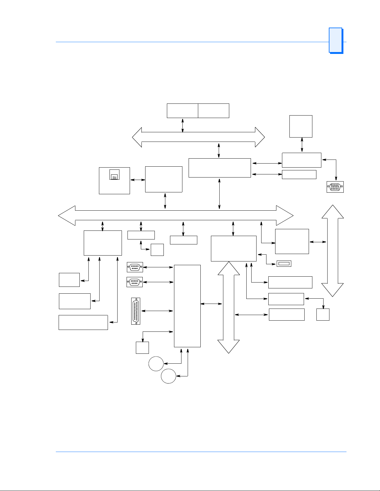
Intel Pentium III
Micro-
Processor
Host bus
1
512 Kbyte
L2 Cache
4MB
Video
DRAM
PLX
PCI Interface
Chip
32-bit
Timer
128 Kbyte
NVRAM
Watchdog Timer
NVRAM Controller DS1384
10BaseT
100BaseTx
SCSI
COM Port 1
COM Port 2
Parallel Port
Floppy Drive
P2
Ethernet
Controller
Intel 21143
PMC Site
P2
PCI bus
SUPER
I/O
with
RTC
SMC
FDC37C67X
North Bridge
82443 BX
System Controller
South Bridge
PCI-to-ISA, IDE
Accelerator
I
S
A
b
u
s
(PIIX4E)
AGP Video
Controller
SDRAM
PCI-to-VME
Bridge
Universe II
USB
Compact Flash
PCI-to-EIDE
Flash BIOS
VGA
V
M
E
b
u
s
P2
Hard
Drive
PS/2
Keyboard
PS/2
Mouse
Figure 1-1 VMIVME-7697 Block Diagram
Artisan Technology Group - Quality Instrumentation ... Guaranteed | (888) 88-SOURCE | www.artisantg.com
27

1 VMIVME-7697 Product Manual
VMEbus Features
In addition to its PC/AT functions, the VMIVME-7697 has the following VMEbus
features:
• Dual-slot, 6U height VMEbus board
• Complete six-line Address Modifier (AM-Code) programmability
• VME data interface with separate hardware byte/word swapping for master
and slave accesses
• Support for VME64 multiplexed MBLT 64-bit VMEbus block transfers
• User-configured interrupter
• U ser-configured interrupt handler
• System Controller mode with programmable VMEbus arbiter
(PRI, SGL, and RRS modes are supported)
• VMEbus BERR* bus error timer (software programmable)
• S lave access from the VMEbus to local RAM and mailbox registers
• Full-featured programmable VMEbus requester
(ROR, RWD, and BCAP modes are supported)
• System Controller autodetection
• Complete VMEbus master access through five separate Protected-Mode
memory windows
Figure 1-2 illustrates the VMIVME- 7697 functions in a typical VMEbus system. The
VMIVME-7697 is a versatile dual-board solution for VMEbus control with familiar
PC/AT operation.
The VMIVME-7697 VMEbus interface is provided by the PCI-to-VMEbus bridge built
around the Tundra Semiconductor Corporation Universe II VMEbus interface chip.
The Universe II provides a reliable high-performance 64-bit VMEbus-to-PCI interface
in one design. The functions and programming of the Universe-based VMEbus
interface are addressed in detail in a separate associated manual titled: The
VMIVME-7697 Tundra Universe II Based VMEbus Interface Product Manual.
28
Artisan Technology Group - Quality Instrumentation ... Guaranteed | (888) 88-SOURCE | www.artisantg.com
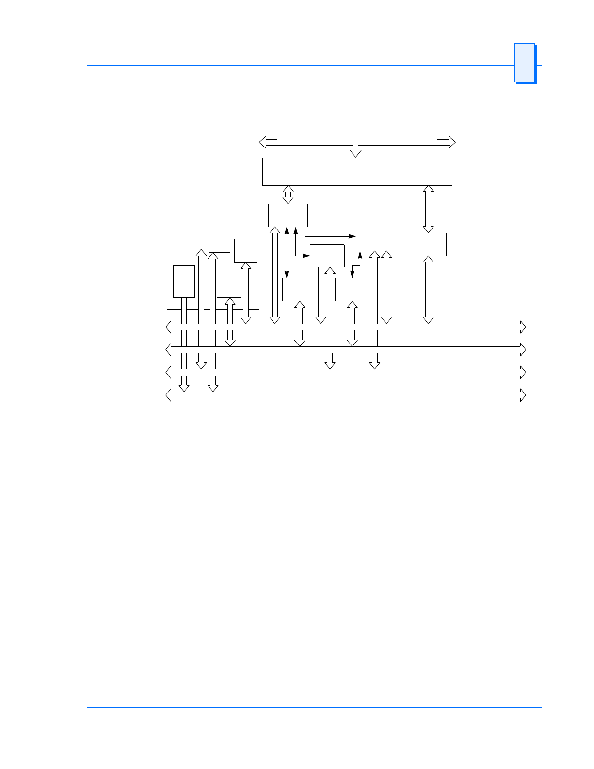
VMIVME-7697
Slot 1 System Controller
Intrpt Ack
Daisy-Chain
Driver
16 MHz
Clock
Driver
System
Reset
Driver
DTB
Arbiter
Bus
Timer
(Program-
mable)
DTB
Master
DTB
Requester
PCI bus
PCI-to-VMEbus Bridge
Interrupt
Interrupter
Stat/ID IQx
Handler
DTB
Requester
VMEbus Features 1
DTB
Slave
Data Transfer Bus
DTB Arbitration
VMIVME-7697 Product Options
VMIC’s VMIVME-7697 is built around three fundamental hardware configurations.
These involve processor perf ormance, S DRAM memory size, and Compact Flash size.
These options are subject to change based on emerging technologies and availability of vendor
configurations.
The options and current details available with the VMIVME-7697 are defined in the
device specification sheet available from your VMIC representative.
Priority Interrupt
Utility
Figure 1-2 VMIVME-7697 VMEbus Functions
Artisan Technology Group - Quality Instrumentation ... Guaranteed | (888) 88-SOURCE | www.artisantg.com
29
 Loading...