

VMIC VMICPCI-7611 Product Manual

Artisan Technology Group is your source for quality
new and certied-used/pre-owned equipment
• FAST SHIPPING AND
DELIVERY
• TENS OF THOUSANDS OF
IN-STOCK ITEMS
• EQUIPMENT DEMOS
• HUNDREDS OF
MANUFACTURERS
SUPPORTED
• LEASING/MONTHLY
RENTALS
• ITAR CERTIFIED
SECURE ASSET SOLUTIONS
SERVICE CENTER REPAIRS
Experienced engineers and technicians on staff
at our full-service, in-house repair center
Instra
Remotely inspect equipment before purchasing with
our interactive website at www.instraview.com
Contact us: (888) 88-SOURCE | sales@artisantg.com | www.artisantg.com
SM
REMOTE INSPECTION
View
WE BUY USED EQUIPMENT
Sell your excess, underutilized, and idle used equipment
We also offer credit for buy-backs and trade-ins
www.artisantg.com/WeBuyEquipment
LOOKING FOR MORE INFORMATION?
Visit us on the web at www.artisantg.com for more
information on price quotations, drivers, technical
specications, manuals, and documentation

VMICPCI-7611
Single Board Embed ded Module Processor-Ba sed
System Slot CompactPCI
Product Manual
®
CPU
12090 South Memorial Parkway
Huntsville, Alabama 35803-3308, USA
(256) 880-0444
Artisan Technology Group - Quality Instrumentation ... Guaranteed | (888) 88-SOURCE | www.artisantg.com
w (800) 322-3616 w Fax: (256) 882-0859
500-657611-000 Rev.A

12090 South Memorial Parkway
Huntsville, Alabama 35803-3308, USA
(256) 880-0444
Artisan Technology Group - Quality Instrumentation ... Guaranteed | (888) 88-SOURCE | www.artisantg.com
w (800) 322-3616 w Fax: (256) 882-0859

COPYRIGHT AND TRADEMARKS
© Copyright 2000. The information in this document has been carefully checked and is believed to be entirely reliable.
While all reasonable efforts to ensure accuracy have been taken in the preparation of this manual, VMIC assumes no
responsibility resulting from omissions or errors in this manual, or from the use of information contained herein.
VMIC reserves the right to make any changes, without notice, to this or any of VMIC’s products to improve reliability,
performance, function, or design.
VMIC does not assume any liability arising out of the application or use of any product or circuit described herein; nor
does VMIC convey any license under its patent rights or the rights of others.
For warranty and repair policies, refer to VMIC’s Standard Conditions of Sale.
AMXbus, BITMODULE, COSMODULE, DMAbus, Instant OPC wizard logo, IOWorks Access, IOWorks Foundation,
IOWorks man figure, IOWorks Manager, IOWorks Server, MAGICWARE, MEGAMODULE, PLC ACCELERATOR
(ACCELERATION), Quick Link, RTnet, Soft Logic Link, SRTbus, TESTCAL, “The Next Generation PLC”, The PLC
Connection, TURBOMODULE, UCLIO, UIOD, UPLC, Visual Soft Logic Control(ler),
VMEmonitor
Logic Experts, and The Total Solutions Provider are service marks of VMIC.
, VMEnet, VMEnet II, and
VMEprobe
are trademarks. The I/O Experts, The I/O Systems Experts, The Soft
VMEaccess, VMEmanager
,
(I/O man figure)
The I/O man figure, IOWorks, UIOC, Visual IOWorks, and
ActiveX is a trademark. Microsoft, Microsoft Access, MS-DOS, Visual Basic, Visual C++, Win32, Windows,
Windows NT, and XENIX are registered trademarks of Microsoft Corporation.
MMX is a trademark and Celeron is a registered trademark of Intel Corporation.
PICMG and CompactPCI are registered trademarks of PCI Industrial Computer Manufacturers’ Group.
Other registered trademarks are the property of their respective owners.
WinUIOC
(IOWorks man figure)(Instant OPC wizard logo)
are registered trademarks of VMIC.
VMIC
All Rights Reserved
This document shall not be duplicated, nor its contents used for any
purpose, unless granted express written permission from VMIC.
Artisan Technology Group - Quality Instrumentation ... Guaranteed | (888) 88-SOURCE | www.artisantg.com

12090 South Memorial Parkway
Huntsville, Alabama 35803-3308, USA
(256) 880-0444
Artisan Technology Group - Quality Instrumentation ... Guaranteed | (888) 88-SOURCE | www.artisantg.com
w (800) 322-3616 w Fax: (256) 882-0859

Table of Contents
Overview
Organization of the Manual
References
Safety Summary
Safety Symbols Used in This Manual
. . . . . . . . . . . . . . . . . . . . . . . . . . . . . . . . . . . . . . . . . . . . . . . . . . . . . . . . . . . . . . . . . . . . . . . . . . . . . . . . . . . . 13
. . . . . . . . . . . . . . . . . . . . . . . . . . . . . . . . . . . . . . . . . . . . . . . . . . . . . . . . . . . . . . . . . 14
. . . . . . . . . . . . . . . . . . . . . . . . . . . . . . . . . . . . . . . . . . . . . . . . . . . . . . . . . . . . . . . . . . . . . . . . . . . . . . . . 15
. . . . . . . . . . . . . . . . . . . . . . . . . . . . . . . . . . . . . . . . . . . . . . . . . . . . . . . . . . . . . . . . . . . . . . . . . . . 17
. . . . . . . . . . . . . . . . . . . . . . . . . . . . . . . . . . . . . . . . . . . . . . . . . . . . . . . . 18
Chapter 1 - Features and Options
CompactPCI Features
VMICPCI-7611 Product Options
. . . . . . . . . . . . . . . . . . . . . . . . . . . . . . . . . . . . . . . . . . . . . . . . . . . . . . . . . . . . . . . . . . . . . . 22
. . . . . . . . . . . . . . . . . . . . . . . . . . . . . . . . . . . . . . . . . . . . . . . . . . . . . . . . . . . . . 23
Chapter 2 - Installation and Setup
Unpacking Procedures
Hardware Setup
Installation
BIOS Setup
Front Panel Connectors
PMC Site Connector
LED Definition
. . . . . . . . . . . . . . . . . . . . . . . . . . . . . . . . . . . . . . . . . . . . . . . . . . . . . . . . . . . . . . . . . . . . . . . . . . . . . . . . . 31
. . . . . . . . . . . . . . . . . . . . . . . . . . . . . . . . . . . . . . . . . . . . . . . . . . . . . . . . . . . . . . . . . . . . . . . . . . . . 32
Chapter 3 - PC/AT Functions
. . . . . . . . . . . . . . . . . . . . . . . . . . . . . . . . . . . . . . . . . . . . . . . . . . . . . . . . . . . . . . . . . . . . . 25
. . . . . . . . . . . . . . . . . . . . . . . . . . . . . . . . . . . . . . . . . . . . . . . . . . . . . . . . . . . . . . . . . . . . . . . . . . . . 26
. . . . . . . . . . . . . . . . . . . . . . . . . . . . . . . . . . . . . . . . . . . . . . . . . . . . . . . . . . . . . . . . 32
. . . . . . . . . . . . . . . . . . . . . . . . . . . . . . . . . . . . . . . . . . . . . . . . . . . . . . . . . . . . . . . . . . . . 33
. . . . . . . . . . . . . . . . . . . . . . . . . . . . . . . . . . . . . . . . . . . . . . . . . . . . . . . . . . . . . . . . . . . . . . . . . . 34
. . . . . . . . . . . . . . . . . . . . . . . . . . . . . . . . . . . . . . . . . . . . . . . . . . . . . . . . . . . . 35
. . . . . . . . . . . . . . . . . . . . . . . . . . . . . . . . . . . . . . . . . . . . . . . . . . . . . . 19
. . . . . . . . . . . . . . . . . . . . . . . . . . . . . . . . . . . . . . . . . . . . . . . . . . . . . 25
CPU Socket
Physical Memory
I/O Port Map
PCI-to-PCI Bridge
PC/AT Interrupts
Integrated Peripherals
Artisan Technology Group - Quality Instrumentation ... Guaranteed | (888) 88-SOURCE | www.artisantg.com
. . . . . . . . . . . . . . . . . . . . . . . . . . . . . . . . . . . . . . . . . . . . . . . . . . . . . . . . . . . . . . . . . . . . . . . . . . . . . . . . 36
. . . . . . . . . . . . . . . . . . . . . . . . . . . . . . . . . . . . . . . . . . . . . . . . . . . . . . . . . . . . . . . . . . . . . . . . . . . 36
. . . . . . . . . . . . . . . . . . . . . . . . . . . . . . . . . . . . . . . . . . . . . . . . . . . . . . . . . . . . . . . . . . . . . . . . . . . . . . . 37
. . . . . . . . . . . . . . . . . . . . . . . . . . . . . . . . . . . . . . . . . . . . . . . . . . . . . . . . . . . . . . . . . . . . . . 39
. . . . . . . . . . . . . . . . . . . . . . . . . . . . . . . . . . . . . . . . . . . . . . . . . . . . . . . . . . . . . . . . . . . . . . . 39
PCI Interrupts
. . . . . . . . . . . . . . . . . . . . . . . . . . . . . . . . . . . . . . . . . . . . . . . . . . . . . . . . . . . . . . . . . . . . . . 42
. . . . . . . . . . . . . . . . . . . . . . . . . . . . . . . . . . . . . . . . . . . . . . . . . . . . . . . . . . . . . . . . . . . . . . 45
5

VMICPCI-7611 Product Manual
Ethernet Controller
10BaseT
100BaseTx
Video Graphics Adapter
. . . . . . . . . . . . . . . . . . . . . . . . . . . . . . . . . . . . . . . . . . . . . . . . . . . . . . . . . . . . . . . . . . . . . . . . . 46
. . . . . . . . . . . . . . . . . . . . . . . . . . . . . . . . . . . . . . . . . . . . . . . . . . . . . . . . . . . . . . . . . . . . . . . . . . . 46
. . . . . . . . . . . . . . . . . . . . . . . . . . . . . . . . . . . . . . . . . . . . . . . . . . . . . . . . . . . . . . . . . . . . . . . . 46
. . . . . . . . . . . . . . . . . . . . . . . . . . . . . . . . . . . . . . . . . . . . . . . . . . . . . . . . . . . . . . . . . . . . 47
Chapter 4 - Embedded PC/RTOS Features
DiskOnChip (Optional)
Installing the DiskOnChip
Configuring the DiskOnChip as the Boot Device
Using the DiskOnChip with Other Operating Systems
Watchdog Timer
Time of Day Registers
Time of Day Alarm Registers
Watchdog Alarm Registers
Command Register
Chapter 5 - Maintenance
Maintenance Prints
Appendix A - Connector Pinouts
. . . . . . . . . . . . . . . . . . . . . . . . . . . . . . . . . . . . . . . . . . . . . . . . . . . . . . . . . . . . . . . . . . . . . . 50
. . . . . . . . . . . . . . . . . . . . . . . . . . . . . . . . . . . . . . . . . . . . . . . . . . . . . . . . . . . . . . . 50
. . . . . . . . . . . . . . . . . . . . . . . . . . . . . . . . . . . . . . . . . . . . . . . . . . . . . . . . . . . . . . . . . . . . . . . . . . . 52
. . . . . . . . . . . . . . . . . . . . . . . . . . . . . . . . . . . . . . . . . . . . . . . . . . . . . . . . . . . . . . . . . . 54
. . . . . . . . . . . . . . . . . . . . . . . . . . . . . . . . . . . . . . . . . . . . . . . . . . . . . . . . . . . . 55
. . . . . . . . . . . . . . . . . . . . . . . . . . . . . . . . . . . . . . . . . . . . . . . . . . . . . . . . . . . . . 56
. . . . . . . . . . . . . . . . . . . . . . . . . . . . . . . . . . . . . . . . . . . . . . . . . . . . . . . . . . . . . . . . . . . . . 56
. . . . . . . . . . . . . . . . . . . . . . . . . . . . . . . . . . . . . . . . . . . . . . . . . . . . . . . . . . . . . . . . . 59
. . . . . . . . . . . . . . . . . . . . . . . . . . . . . . . . . . . . . . . . . . . . . . . . . . . . . . . . . . . . . . . . . . . . . . . . . 59
. . . . . . . . . . . . . . . . . . . . . . . . . . . . . . . . . . . . . . . . . . . . . . . . . . . . . . . 61
. . . . . . . . . . . . . . . . . . . . . . . . . . . . . . . . . . . . . . . . . . . 49
. . . . . . . . . . . . . . . . . . . . . . . . . . . . . . . . . . . . . . . . . 50
. . . . . . . . . . . . . . . . . . . . . . . . . . . . . . . . . . . . 51
J1 Connector Pinout
J2 Connector and Pinout
J3 Connector Pinout
J5 Connector and Pinout
Ethernet Connector Pinout (J14)
Video Connector Pinout (J11)
Parallel Port Connector Pinout (P2)
Keyboard and Mouse Connectors and Pinout (J10)
USB Connector (J9)
PMC Connector Pinout
PMC J7 Connector and Pinout
PMC J6 Connector and Pinout
PMC J4 Connector and Pinout
Appendix B - Phoenix BIOS
System BIOS Setup Utility
Help Window
First Boot
. . . . . . . . . . . . . . . . . . . . . . . . . . . . . . . . . . . . . . . . . . . . . . . . . . . . . . . . . . . . . . . . . . . . . . . . . . . . . . . . . . 76
. . . . . . . . . . . . . . . . . . . . . . . . . . . . . . . . . . . . . . . . . . . . . . . . . . . . . . . . . . . . . . . . . . . . . . . . 63
. . . . . . . . . . . . . . . . . . . . . . . . . . . . . . . . . . . . . . . . . . . . . . . . . . . . . . . . . . . . . . . . . . . 64
. . . . . . . . . . . . . . . . . . . . . . . . . . . . . . . . . . . . . . . . . . . . . . . . . . . . . . . . . . . . . . . . . . . . . . . . 65
. . . . . . . . . . . . . . . . . . . . . . . . . . . . . . . . . . . . . . . . . . . . . . . . . . . . . . . . . . . . . . . . . . . 66
. . . . . . . . . . . . . . . . . . . . . . . . . . . . . . . . . . . . . . . . . . . . . . . . . . . . . . . . . . . . 67
. . . . . . . . . . . . . . . . . . . . . . . . . . . . . . . . . . . . . . . . . . . . . . . . . . . . . . . . . . . . . . . 68
. . . . . . . . . . . . . . . . . . . . . . . . . . . . . . . . . . . . . . . . . . . . . . . . . . . . . . . . . 69
. . . . . . . . . . . . . . . . . . . . . . . . . . . . . . . . . . . . . . . . . . . . . . . . . . . . . . . . . . . . . . . . . . . . . . . . 71
. . . . . . . . . . . . . . . . . . . . . . . . . . . . . . . . . . . . . . . . . . . . . . . . . . . . . . . . . . . . . . . . . . . . . 72
. . . . . . . . . . . . . . . . . . . . . . . . . . . . . . . . . . . . . . . . . . . . . . . . . . . . . . 72
. . . . . . . . . . . . . . . . . . . . . . . . . . . . . . . . . . . . . . . . . . . . . . . . . . . . . . 73
. . . . . . . . . . . . . . . . . . . . . . . . . . . . . . . . . . . . . . . . . . . . . . . . . . . . . . 74
. . . . . . . . . . . . . . . . . . . . . . . . . . . . . . . . . . . . . . . . . . . . . . . . . . . . . . . . . . . . . 75
. . . . . . . . . . . . . . . . . . . . . . . . . . . . . . . . . . . . . . . . . . . . . . . . . . . . . . . . . . . . . . 75
. . . . . . . . . . . . . . . . . . . . . . . . . . . . . . . . . . . . . . . . . . . . . . . . . . . . . . . . . . . . . . . . . . . . . . . . . . . 75
. . . . . . . . . . . . . . . . . . . . . . . . . . . . . . . . . . . . . . . . . . 70
6
Artisan Technology Group - Quality Instrumentation ... Guaranteed | (888) 88-SOURCE | www.artisantg.com

Table of Contents
Main Menu
QuickBoot
Setting The Time
Setting The Date
Legacy Diskette
. . . . . . . . . . . . . . . . . . . . . . . . . . . . . . . . . . . . . . . . . . . . . . . . . . . . . . . . . . . . . . . . . . . . . . . . . . . . . . . . . 77
. . . . . . . . . . . . . . . . . . . . . . . . . . . . . . . . . . . . . . . . . . . . . . . . . . . . . . . . . . . . . . . . . . . . . . . . . . . . . . 77
. . . . . . . . . . . . . . . . . . . . . . . . . . . . . . . . . . . . . . . . . . . . . . . . . . . . . . . . . . . . . . . . . . . . . . . 77
. . . . . . . . . . . . . . . . . . . . . . . . . . . . . . . . . . . . . . . . . . . . . . . . . . . . . . . . . . . . . . . . . . . . . . . 77
. . . . . . . . . . . . . . . . . . . . . . . . . . . . . . . . . . . . . . . . . . . . . . . . . . . . . . . . . . . . . . . . . . . . . . . . 78
Floppy Drive A
Floppy Drive B
Primary Master/Slave
Secondary Master
. . . . . . . . . . . . . . . . . . . . . . . . . . . . . . . . . . . . . . . . . . . . . . . . . . . . . . . . . . . . . . . . . . . . . . 79
Keyboard Features
NumLock
Key Click
. . . . . . . . . . . . . . . . . . . . . . . . . . . . . . . . . . . . . . . . . . . . . . . . . . . . . . . . . . . . . . . . . . . . . . . . . . 79
. . . . . . . . . . . . . . . . . . . . . . . . . . . . . . . . . . . . . . . . . . . . . . . . . . . . . . . . . . . . . . . . . . . . . . . . . . . 79
Keyboard Auto-Repeat Rate (Chars/Sec)
Keyboard Auto-Repeat Delay (sec)
Keyboard Test
System Memory
Extended Memory
Extended Memory
. . . . . . . . . . . . . . . . . . . . . . . . . . . . . . . . . . . . . . . . . . . . . . . . . . . . . . . . . . . . . . . . . . . . . . . . 80
. . . . . . . . . . . . . . . . . . . . . . . . . . . . . . . . . . . . . . . . . . . . . . . . . . . . . . . . . . . . . . . . . . . . . . 80
. . . . . . . . . . . . . . . . . . . . . . . . . . . . . . . . . . . . . . . . . . . . . . . . . . . . . . . . . . . . . . . . . . . . . . 80
Console Redirection
Com Port Address
Baud Rate
Console Type
Flow Control
. . . . . . . . . . . . . . . . . . . . . . . . . . . . . . . . . . . . . . . . . . . . . . . . . . . . . . . . . . . . . . . . . . . . . . . . . 81
. . . . . . . . . . . . . . . . . . . . . . . . . . . . . . . . . . . . . . . . . . . . . . . . . . . . . . . . . . . . . . . . . . . . . . 81
. . . . . . . . . . . . . . . . . . . . . . . . . . . . . . . . . . . . . . . . . . . . . . . . . . . . . . . . . . . . . . . . . . . . . . . 81
Console Connection
Continue C.R. After POST
Advanced Menu
Installed O/S
. . . . . . . . . . . . . . . . . . . . . . . . . . . . . . . . . . . . . . . . . . . . . . . . . . . . . . . . . . . . . . . . . . . . . . . . . . . . 82
. . . . . . . . . . . . . . . . . . . . . . . . . . . . . . . . . . . . . . . . . . . . . . . . . . . . . . . . . . . . . . . . . . . . . . . . . . . 82
Reset Configuration Data
Cache Memory
. . . . . . . . . . . . . . . . . . . . . . . . . . . . . . . . . . . . . . . . . . . . . . . . . . . . . . . . . . . . . . . . . . . . . . . . . 82
I/O Device Configuration
Large Disk Access Mode
Local Bus IDE Adapter
Advanced Chipset Control
Graphics Aperture
Enable Memory Map
ECC Config
. . . . . . . . . . . . . . . . . . . . . . . . . . . . . . . . . . . . . . . . . . . . . . . . . . . . . . . . . . . . . . . . . . . . . . . . 85
SERR Signal Configuration
Clear Watchdog Timer Reset
. . . . . . . . . . . . . . . . . . . . . . . . . . . . . . . . . . . . . . . . . . . . . . . . . . . . . . . . . . . . . . . . . . . . . 78
. . . . . . . . . . . . . . . . . . . . . . . . . . . . . . . . . . . . . . . . . . . . . . . . . . . . . . . . . . . . . . . . . . . . . 78
. . . . . . . . . . . . . . . . . . . . . . . . . . . . . . . . . . . . . . . . . . . . . . . . . . . . . . . . . . . . . . . . . . . 78
. . . . . . . . . . . . . . . . . . . . . . . . . . . . . . . . . . . . . . . . . . . . . . . . . . . . . . . . . . . . . . . . . . . . . 79
. . . . . . . . . . . . . . . . . . . . . . . . . . . . . . . . . . . . . . . . . . . . 79
. . . . . . . . . . . . . . . . . . . . . . . . . . . . . . . . . . . . . . . . . . . . . . . . . . 80
. . . . . . . . . . . . . . . . . . . . . . . . . . . . . . . . . . . . . . . . . . . . . . . . . . . . . . . . . . . . . . . . . . . . . 80
. . . . . . . . . . . . . . . . . . . . . . . . . . . . . . . . . . . . . . . . . . . . . . . . . . . . . . . . . . . . . . . . . . . . 80
. . . . . . . . . . . . . . . . . . . . . . . . . . . . . . . . . . . . . . . . . . . . . . . . . . . . . . . . . . . . . . . . . . 81
. . . . . . . . . . . . . . . . . . . . . . . . . . . . . . . . . . . . . . . . . . . . . . . . . . . . . . . . . . . . . . . . 81
. . . . . . . . . . . . . . . . . . . . . . . . . . . . . . . . . . . . . . . . . . . . . . . . . . . . . . . . . . 81
. . . . . . . . . . . . . . . . . . . . . . . . . . . . . . . . . . . . . . . . . . . . . . . . . . . . . . . . . . . . . . . 82
. . . . . . . . . . . . . . . . . . . . . . . . . . . . . . . . . . . . . . . . . . . . . . . . . . . . . . . . . . . . . . . . 83
. . . . . . . . . . . . . . . . . . . . . . . . . . . . . . . . . . . . . . . . . . . . . . . . . . . . . . . . . . . . . . . 84
. . . . . . . . . . . . . . . . . . . . . . . . . . . . . . . . . . . . . . . . . . . . . . . . . . . . . . . . . . . . . . . . . 84
. . . . . . . . . . . . . . . . . . . . . . . . . . . . . . . . . . . . . . . . . . . . . . . . . . . . . . . . . . . . . . 84
. . . . . . . . . . . . . . . . . . . . . . . . . . . . . . . . . . . . . . . . . . . . . . . . . . . . . . . . . . . . . . . . . . 84
. . . . . . . . . . . . . . . . . . . . . . . . . . . . . . . . . . . . . . . . . . . . . . . . . . . . . . . . . . . . . . . 85
. . . . . . . . . . . . . . . . . . . . . . . . . . . . . . . . . . . . . . . . . . . . . . . . . . . . . . . . . 85
. . . . . . . . . . . . . . . . . . . . . . . . . . . . . . . . . . . . . . . . . . . . . . . . . . . . . . . . . . . 85
Artisan Technology Group - Quality Instrumentation ... Guaranteed | (888) 88-SOURCE | www.artisantg.com
7

VMICPCI-7611 Product Manual
Assign Interrupt To USB
Legacy Keyboard/Mouse
Power
Boot Menu
Exit Menu
. . . . . . . . . . . . . . . . . . . . . . . . . . . . . . . . . . . . . . . . . . . . . . . . . . . . . . . . . . . . . . . . . . . . . . . . . . . . . . . . . . . . . 86
. . . . . . . . . . . . . . . . . . . . . . . . . . . . . . . . . . . . . . . . . . . . . . . . . . . . . . . . . . . . . . . . . . . . . . . . . . . . . . . . . 87
. . . . . . . . . . . . . . . . . . . . . . . . . . . . . . . . . . . . . . . . . . . . . . . . . . . . . . . . . . . . . . . . . . . . . . . . . . . . . . . . . . 88
Exit Saving Changes
Exit Discarding Changes
Load Setup Defaults
Discard Changes
Save Changes
. . . . . . . . . . . . . . . . . . . . . . . . . . . . . . . . . . . . . . . . . . . . . . . . . . . . . . . . . . . . . . . . . . . . . . . . . 88
. . . . . . . . . . . . . . . . . . . . . . . . . . . . . . . . . . . . . . . . . . . . . . . . . . . . . . . . . . . . . . . . . . . . . . . 88
. . . . . . . . . . . . . . . . . . . . . . . . . . . . . . . . . . . . . . . . . . . . . . . . . . . . . . . . . . . . . . . . 85
. . . . . . . . . . . . . . . . . . . . . . . . . . . . . . . . . . . . . . . . . . . . . . . . . . . . . . . . . . . . . . . 85
. . . . . . . . . . . . . . . . . . . . . . . . . . . . . . . . . . . . . . . . . . . . . . . . . . . . . . . . . . . . . . . . . . . 88
. . . . . . . . . . . . . . . . . . . . . . . . . . . . . . . . . . . . . . . . . . . . . . . . . . . . . . . . . . . . . . . . 88
. . . . . . . . . . . . . . . . . . . . . . . . . . . . . . . . . . . . . . . . . . . . . . . . . . . . . . . . . . . . . . . . . . . . 88
Appendix C - Device Configuration: I/O and Interrupt Control
BIOS Operations
BIOS Control Overview
Functional Overview
Data Book References
Device Address Definition
ISA Devices
PCI Devices
Device Interrupt Definition
PC/AT Interrupt Definition
ISA Device Interrupt Map
PCI Device Interrupt Map
. . . . . . . . . . . . . . . . . . . . . . . . . . . . . . . . . . . . . . . . . . . . . . . . . . . . . . . . . . . . . . . . . . . . . . . . . . . 90
. . . . . . . . . . . . . . . . . . . . . . . . . . . . . . . . . . . . . . . . . . . . . . . . . . . . . . . . . . . . . . . . . 90
. . . . . . . . . . . . . . . . . . . . . . . . . . . . . . . . . . . . . . . . . . . . . . . . . . . . . . . . . . . . . . . . . . . . 90
. . . . . . . . . . . . . . . . . . . . . . . . . . . . . . . . . . . . . . . . . . . . . . . . . . . . . . . . . . . . . . . . . 92
. . . . . . . . . . . . . . . . . . . . . . . . . . . . . . . . . . . . . . . . . . . . . . . . . . . . . . . . . . . . . . . . . . 94
. . . . . . . . . . . . . . . . . . . . . . . . . . . . . . . . . . . . . . . . . . . . . . . . . . . . . . . . . . . . . . . . . . . . . . . . . . . . 94
. . . . . . . . . . . . . . . . . . . . . . . . . . . . . . . . . . . . . . . . . . . . . . . . . . . . . . . . . . . . . . . . . . . . . . . . . . . 95
. . . . . . . . . . . . . . . . . . . . . . . . . . . . . . . . . . . . . . . . . . . . . . . . . . . . . . . . . . . . . . . . . . 96
. . . . . . . . . . . . . . . . . . . . . . . . . . . . . . . . . . . . . . . . . . . . . . . . . . . . . . . . . . . . . . . 96
. . . . . . . . . . . . . . . . . . . . . . . . . . . . . . . . . . . . . . . . . . . . . . . . . . . . . . . . . . . . . . . 96
. . . . . . . . . . . . . . . . . . . . . . . . . . . . . . . . . . . . . . . . . . . . . . . . . . . . . . . . . . . . . . . 98
. . . . . . . . . . . . . . . . . . . . 89
8
Artisan Technology Group - Quality Instrumentation ... Guaranteed | (888) 88-SOURCE | www.artisantg.com

List of Figures
Figure 1-1 VMICPCI-7611 Block Diagram . . . . . . . . . . . . . . . . . . . . . . . . . . . . . . . . . . . . . . . . . . . . . . 21
Figure 2-1 VMICPCI-7611 Embedded Module, and Jumper Locations . . . . . . . . . . . . . . . . . . . . . . . . 27
Figure 2-2 Installing a PMC Card on the VMICPCI-7611 . . . . . . . . . . . . . . . . . . . . . . . . . . . . . . . . . . . 33
Figure 2-3 Front Panel LED Positions . . . . . . . . . . . . . . . . . . . . . . . . . . . . . . . . . . . . . . . . . . . . . . . . . . 34
Figure 3-1 Connections for the PC Interrupt Logic Controller . . . . . . . . . . . . . . . . . . . . . . . . . . . . . . . . 44
Figure 4-2 Watchdog Alarm Block . . . . . . . . . . . . . . . . . . . . . . . . . . . . . . . . . . . . . . . . . . . . . . . . . . . . . 52
Figure A-1 VMICPCI-7611 Connector and Jumper Locations . . . . . . . . . . . . . . . . . . . . . . . . . . . . . . . . 62
Figure A-2 J1 Connector and Pinout . . . . . . . . . . . . . . . . . . . . . . . . . . . . . . . . . . . . . . . . . . . . . . . . . . . 63
Figure A-3 J2 Connector and Pinout . . . . . . . . . . . . . . . . . . . . . . . . . . . . . . . . . . . . . . . . . . . . . . . . . . . 64
Figure A-4 J3 Connector and Pinout . . . . . . . . . . . . . . . . . . . . . . . . . . . . . . . . . . . . . . . . . . . . . . . . . . . 65
Figure A-5 J5 Connector and Pinout . . . . . . . . . . . . . . . . . . . . . . . . . . . . . . . . . . . . . . . . . . . . . . . . . . . 66
Figure A-6: Ethernet Connector and Pinout . . . . . . . . . . . . . . . . . . . . . . . . . . . . . . . . . . . . . . . . . . . . . . 67
Figure A-7 Video Connector and Pinout . . . . . . . . . . . . . . . . . . . . . . . . . . . . . . . . . . . . . . . . . . . . . . . . 68
Figure A-8 P2 Connector and Pinout . . . . . . . . . . . . . . . . . . . . . . . . . . . . . . . . . . . . . . . . . . . . . . . . . . . 69
Figure A-9 Keyboard/Mouse Connector and Pinout . . . . . . . . . . . . . . . . . . . . . . . . . . . . . . . . . . . . . . . 70
Figure A-10 USB Connector Pinout . . . . . . . . . . . . . . . . . . . . . . . . . . . . . . . . . . . . . . . . . . . . . . . . . . . . . 71
Figure C-1 VMICPCI-7611 Block Diagram . . . . . . . . . . . . . . . . . . . . . . . . . . . . . . . . . . . . . . . . . . . . . . 91
Figure C-2 BIOS Default Connections for the PC Interrupt Logic Controller . . . . . . . . . . . . . . . . . . . . . 97
Artisan Technology Group - Quality Instrumentation ... Guaranteed | (888) 88-SOURCE | www.artisantg.com
9

VMICPCI-7611 Product Manual
10
Artisan Technology Group - Quality Instrumentation ... Guaranteed | (888) 88-SOURCE | www.artisantg.com

List of Tables
Table 1-1 PC/AT I/O Features
Table 2-1 CPU Board Connectors
Table 2-2 Password Clear (User Configurable) - Jumper (E3)
Table 2-3 Factory Configured - PIlX4E Battery Jumper (E6)
Table 2-4 Factory Configured - Watchdog Timer jumper (E7)
Table 2-5 Factory Configured - Clock Speed Select Jumper (E8)
Table 2-6 Factory Configured - Watchdog Battery Jumper (E10)
Table 2-7 Factory Configured - Reserved Jumper (E12)
Table 2-8 Factory Configured - DiskOnChip Address SEL Jumper (E13)
Table 2-9 Factory Configured - Boot Block Lock Jumper (E17)
Table 2-10 Factory Configured - Boot Block Lock (E18)
Table 3-1 VMICPCI-7611 I/O Address Map
Table 3-2 PC/AT Hardware Interrupt Line Assignments
Table 3-3 PC/AT Interrupt Vector Table
Table 3-4 NMI Register Bit Descriptions
Table 3-5 Supported Graphics Video Resolutions
Table 4-6 Watchdog Registers
Table 4-7 Time of Day Alarm Registers
Table A-1 Keyboard/Mouse Y Splitter Cable
Table A-2 PMC J7 Connector Pinout
Table A-3 PMC J6 Connector Pinout
Table A-4 PMC J4 Connector Pinout
Table C-1 ISA Device Mapping Configuration
Table C-2 PCI Device Mapping Configuration
Table C-3 PCI Device Interrupt Mapping by the BIOS
. . . . . . . . . . . . . . . . . . . . . . . . . . . . . . . . . . . . . . . . . . . . . . . . . . . . . . . . . . . . . 20
. . . . . . . . . . . . . . . . . . . . . . . . . . . . . . . . . . . . . . . . . . . . . . . . . . . . . . . . . . 28
. . . . . . . . . . . . . . . . . . . . . . . . . . . . . . . . 28
. . . . . . . . . . . . . . . . . . . . . . . . . . . . . . . . . 29
. . . . . . . . . . . . . . . . . . . . . . . . . . . . . . . . 29
. . . . . . . . . . . . . . . . . . . . . . . . . . . . 29
. . . . . . . . . . . . . . . . . . . . . . . . . . . . . 29
. . . . . . . . . . . . . . . . . . . . . . . . . . . . . . . . . . . . . 29
. . . . . . . . . . . . . . . . . . . . . . . . . . . . . . . 30
. . . . . . . . . . . . . . . . . . . . . . . . . . . . . . . . . . . . . . 30
. . . . . . . . . . . . . . . . . . . . . . . . . . . . . . . . . . . . . . . . . . . . . . . . . 37
. . . . . . . . . . . . . . . . . . . . . . . . . . . . . . . . . . . . 39
. . . . . . . . . . . . . . . . . . . . . . . . . . . . . . . . . . . . . . . . . . . . . . . . . . . . 40
. . . . . . . . . . . . . . . . . . . . . . . . . . . . . . . . . . . . . . . . . . . . . . . . . . . . 43
. . . . . . . . . . . . . . . . . . . . . . . . . . . . . . . . . . . . . . . . . . . 47
. . . . . . . . . . . . . . . . . . . . . . . . . . . . . . . . . . . . . . . . . . . . . . . . . . . . . . . . . . . . . 53
. . . . . . . . . . . . . . . . . . . . . . . . . . . . . . . . . . . . . . . . . . . . . . . . . . . . . 55
. . . . . . . . . . . . . . . . . . . . . . . . . . . . . . . . . . . . . . . . . . . . . . . . . 70
. . . . . . . . . . . . . . . . . . . . . . . . . . . . . . . . . . . . . . . . . . . . . . . . . . . . . . . 72
. . . . . . . . . . . . . . . . . . . . . . . . . . . . . . . . . . . . . . . . . . . . . . . . . . . . . . . 73
. . . . . . . . . . . . . . . . . . . . . . . . . . . . . . . . . . . . . . . . . . . . . . . . . . . . . . . 74
. . . . . . . . . . . . . . . . . . . . . . . . . . . . . . . . . . . . . . . . . . . . . . . 94
. . . . . . . . . . . . . . . . . . . . . . . . . . . . . . . . . . . . . . . . . . . . . . . 95
. . . . . . . . . . . . . . . . . . . . . . . . . . . . . . . . . . . . . . . . 98
. . . . . . . . . . . . . . . . . . . . . 30
Artisan Technology Group - Quality Instrumentation ... Guaranteed | (888) 88-SOURCE | www.artisantg.com
11

VMICPCI-7611 Product Manual
12
Artisan Technology Group - Quality Instrumentation ... Guaranteed | (888) 88-SOURCE | www.artisantg.com

Overview
Introduction
VMIC’s VMICPCI-7611 is a complete IBM PC/AT-compatible Pentium II/III
Embedded Module processor-based computer with the additional benefits of
Eurocard construction and full compatibility with the CompactPCI Specification
Rev. 2.1. The VMICPCI-7611 with advanced CPCI interface and SDRAM that is
dual-ported to the CPCI bus, is ideal for CPCI system controller applications.
The single-slot CPU board functions as a standard PC/AT, executing a PC/AT-type
power-on se lf-test, then boots up MS-DOS, Windows 3.11, W indows 95, W i ndows NT ,
or any other PC/AT-compatible operating system. The PC/AT mode of the
VMICPCI-7611 is discussed in Chapter 3 of this manual.
The VMICPCI-7611 also operates as a CPCI system slot CPU and interacts with other
CPCI modules via the on-board embedded bridge.
The VMICPCI-7611 also provides capabilities beyond the features of a typical PC/AT
compatible CPU including a programmable watchdog timer and a bootable flash disk
system. These features makethe unit ideal for embedded applications. These
nonstandard PC/AT functions are discussed in Chapter 4 of this manual.
Artisan Technology Group - Quality Instrumentation ... Guaranteed | (888) 88-SOURCE | www.artisantg.com
13

VMICPCI-7611 Product Manual
Organization of the Manual
This manual is composed of the following chapters and appendices:
Chapter 1 - Features and Options describes the features of the base unit followed by
descriptions of the associated features of the unit in operation on a CPCI bus.
Chapter 2 - Installation and Setup describes unpacking, inspection, hardware jumper
settings, connector definitions, installation, system setup, and operation of the
VMICPCI-7611.
Chapter 3 - PC/AT Functions describes the unit design in terms of the standard PC
memory and I/O maps, along with the standard interrupt architecture.
Chapter 4 - Embedded PC/RTOS Features describes the unit features that are beyond
standard PC/AT functions.
Chapter 5 - Maintenance provides infor mation r elative to the care an d maintenance of
the unit.
Appendix A - Connector Pinouts illustrates and defines the connectors included in the
unit’s I/O ports.
Appendix B - Phoenix BIOS describes the menus and options associated with the
Phoenix BIOS.
Appendix D - Device Configuration: I/O and Interrupt Control provides the user with
the information needed to develop custom applications such as the revision of the
current BIOS configuration to a user-specific configuration.
14
Artisan Technology Group - Quality Instrumentation ... Guaranteed | (888) 88-SOURCE | www.artisantg.com

References
References
For the most up-to-date specifications for the VMICPCI-7611, please refer to:
Pentium II/III Processor with MMXTM Technology
Intel Corporation
2200 Mission College Blvd.
P.O. Box 58119
Santa Clara, CA 95052-8119
(408) 765-8080
Intel 82440BX AGP set: 82443BX Host Bridge/Controller
Intel Corporation
2200 Mission College Boulevard
P.O. Box 58119
Santa Clara, CA 95052-8119
Intel 21154 PCI-to-PCI Bridge
Intel Corporation
2200 Mission College Boulevard
P.O. Box 58119
Santa Clara, CA 95052-8119
Intel 82559 10/100 Mb/s Ethernet LAN Controller
Intel Corporation
2200 Mission College Boulevard
P.O. Box 58119
Santa Clara, CA 95052-8119
Intel 82440BX PCIset ISA Bridge
82371EB PCI ISA IDE Xcellerator (PIIX4E)
2200 Mission College Boulevard
P.O. Box 58119
Santa Clara, CA 95052-8119
PCI Local Bus Specification, Rev. 2.1
PCI Specia l Interest Group
P.O. Box 14070
Portland, OR 97214
(800) 433-5177 (U.S.)
(503) 797-4207 (International)
(503) 234-6762 (FAX)
SMC FDC37C67X Enhanced Super I/O Controller
SMC Component Products Division
300 Kennedy Drive
Hauppauge, NY 11788
(516) 435-6000
(516) 231-6004 (FAX)
Artisan Technology Group - Quality Instrumentation ... Guaranteed | (888) 88-SOURCE | www.artisantg.com
15

VMICPCI-7611 Product Manual
ISA & EISA, Theory and Operation
Solari, Edward
Annabooks
15010 Avenue of Science, Suite 101
San Diego, CA 92128 USA
ISBN 0-929392 -15-9
DS 1284 Watchdog Timekeeping Controller
Dallas Semiconductor
4461 South Beltwood Pwky.
Dallas, TX 75244-3292
M-Systems Corporate Headquarters
USA Office
39899 Balentine Dr.
Suite 335
Newark, CA 94560
Tel: 510-413-5950
Fax: 510-413-5980
Email: info@m-sys.com
Intel 69000AGP Video Controller
Intel Corporation
P.O. Box 58119
Santa Clara, CA 95052-8119
(408) 765-8080
www.intel.com
CMC Specification, P1386/Draft 2.0 from:
IEEE Standards Department
Copyrights and Permissions
445 Hoes Lanes, P.O. Box 1331
Piscataway, NJ 08855-1331, USA
PMC Specification, P1386.1/Draft 2.0 from:
IEEE Standards Department
Copyrights and Permissions
445 Hoes Lanes, P.O. Box 1331
Piscataway, NJ 08855-1331, USA
For a detailed description and specification of the CompactPCI bus, please refer to:
CompactPCI
PCI Industrial Computer Manufactures’ Group
TM
Specification PICMG 2.0 R2.1
301 Edgewater Place
Suite 220
Wakefield, MA 01880
(617) 224-1100
(617) 224-1239 (FAX)
www.picmg.org (Web)
16
Artisan Technology Group - Quality Instrumentation ... Guaranteed | (888) 88-SOURCE | www.artisantg.com

Safety Summary
WARNING
The following general safety precautions must be observed during all phases of the
operation, service, and repair of this product. Failure to comply with these
precautions or with specific warnings elsewhere in this manual violates safety
standards of design, manufacture, and intended use of this product.
VMIC assumes no liability for the customer’s failure to comply with these
requirements.
Ground the System
To minimize shock hazard, the chassis and system cabinet must be connected to an
electrical ground. A three-conductor AC power cable should be used. The power
cable must either be plugged into an approved three-contact electrical outlet or used
with a three-contact to two-contact adapter with the grounding wire (green) firmly
connected to an electrical ground (safety ground) at the power outlet.
Do Not Operate in an Explosive Atmosphere
Do not operate the system in the presence of flammable gases or fumes. Operation of
any electrical system in such an environment constitutes a definite safety hazard.
Safety Summary
Keep Away from Live Circuits
Operating personnel must not remove product covers. Component replacement and
internal adjustments must be made by qualified maintenance personnel. Do not
replace components with power cable connected. Under certain conditions,
dangerous voltages may exist even with the power cable removed. To avoid injuries,
always disconnect power and discharge circuits before touching them.
Do Not Service or Adjust Alone
Do not attempt internal service or adjustment unless another person capable of
rendering first aid and resuscitation is present.
Do Not Substitute Parts or Modify System
Because of the danger of introducing additional hazards, do not install substitute
parts or perform any unauthorized modification to the product. Return the product to
VMIC for service and repair to ensure that safety features are maintained.
Dangerous Procedure Warnings
Warnings, such as the example below, precede only potentially danger ous pr ocedures
throughout this manual. Instructions contained in the warnings must be followed.
Dangerous voltages, capable of causing death, are pr esent in this system. Use extre me
caution when handling , t es t ing, and adjusting.
17
Artisan Technology Group - Quality Instrumentation ... Guaranteed | (888) 88-SOURCE | www.artisantg.com

VMICPCI-7611 Product Manual
Safety Symbols Used in This Manual
Indicates dangerous voltage (terminals fed from the interior by voltage exceeding
1000 V are so marked).
OR
OR
Protective conductor terminal. For protection against electrical shock in ca se of a fault.
Used with field wiring terminals to indicate the terminal which must be connected to
ground before operating equipment.
Low-noise or noiseless, clean ground (earth) terminal. Used for a signal common, as
well as providing protection against electrical shock in case of a fault. Before
operating the equipment, terminal marked with this symbol must be connected to
ground in the manner described in the installation (operation) manual.
Frame or chassis terminal. A connection to the frame (ch assis) of the equipment which
normally includes all exposed metal structures.
Alternating current (power line).
Direct current (power line).
Alternating or direct current (power line).
STOP: informs the operator that a practice or procedure should not be performed.
Actions could result in injury or death to personnel, or could result in damage to or
destruction of part or all of the system.
18
WARNING: denotes a hazard. It calls attention to a procedure, a practice, or
condition, which, if not correctly performed or adhered to, could result in injury or
death to personnel.
CAUTION: calls attention to an operating procedure, a practice, or a condition,
which, if not correctly performed or adhered to, could result in damage to or
destruction of part or all of the system.
NOTE: denotes important information. It calls attention to a procedure, a practice, or
condition which is essential to highlight.
Artisan Technology Group - Quality Instrumentation ... Guaranteed | (888) 88-SOURCE | www.artisantg.com

Features and Options
Contents
CompactPCI Features . . . . . . . . . . . . . . . . . . . . . . . . . . . . . . . . . . . . . . . . . . . . . . . . 22
VMICPCI-7611 Product Options . . . . . . . . . . . . . . . . . . . . . . . . . . . . . . . . . . . . . . . 23
Introduction
The VMICPCI-7611 performs all the functions of a standard IBM PC/A T motherboar d
with the following features:
CHAPTER
1
• Sing le-slot CPCI bus 6U Eurocard form factor
• Incl udes a high -performa nce Intel Pentium II/III Embedded Module processor
• Up to 256 Mbyte of Synchronous DRAM
• AGP video with 2 Mbyte SDRAM
• Real-time clock/calendar
• Front panel reset switch
• Onboard port for keyboard and mouse
• UltraEIDE hard drive, floppy drive through the CPCI J3 connector
• Onboard fast Ethernet controller supporting 10BaseT and 100BaseTX interfaces
• Front panel “vital sign” indicators (power , UltraEID E hard drive activity , Ready ,
and Ethernet status)
• Software-selectable watchdog timer with reset
• Optional M-Systems DiskOnChip flash memory (12 to 72 Mbyte available)
• Two Serial ports, one available by way of the front panel RJ11 connector and
both available through the CPCI J3 connector
• One enhanced parallel port available on the front panel and through the CPCI
J3 connector
• Two USB Ports: one available on the front panel, and one through the CPCI J3
connector (rear I/O)
The VMICPCI-7611 supports standard PC/AT I/O features such as those listed in
Table 1-1. Figure 1-1 on page 21 shows a block diagram of the VMICPCI-7611
emphasizing the I/O features, including the PCI-to-PCI bridge. The serial, parallel,
IDE, and floppy signals are also routed through the backplane.
Artisan Technology Group - Quality Instrumentation ... Guaranteed | (888) 88-SOURCE | www.artisantg.com
19
1
VMICPCI-7611 Product Manual
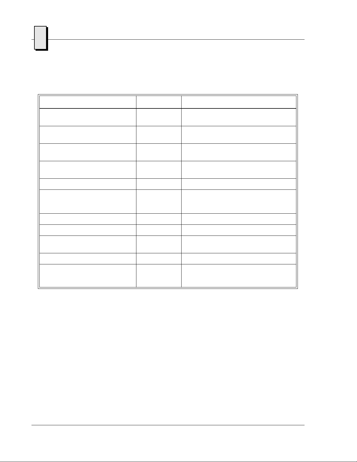
I/O FEATURE IDENTIFIER PHYSICAL ACCESS
Table 1-1 PC/AT I/O Features
Two high-performance
16550-compatible serial port
One Enhanced Parallel Port, Supports
ECP/EPP Modes
AT-Style Keyboard/Mouse Controller M/K Front Panel PS/2-Style Connector, Mini-DIN
AGP Video Controller with 2 Mbyte
SDRAM
Real-Time Clock/Calendar Date, Time
On-board fast Ethernet controller
supporting 10BaseT and 100BaseTX
interfaces
Floppy Dis k Controller Drive A Through CPCI J3
Ultra EIDE Hard Drive Controller Drive C Through CPCI J3
T w o USB Ports USB One through the front panel, the ot her t hr ough
Hardware Reset RST Front Panel Push-Button
Power Status, Hard Drive Activity,
Ready, and Ethernet Status for each
controller
COM1, COM2 One through the front panel RJ11, both
through CPCI J3 Connector (See Note)
Parallel Through front panel and CPCI J3 connector
(See Note)
Circular (female)
SVGA Front Panel DB15HD High Density (female)
LAN Front Panel R-J45
CPCI J3
LED Indicators Front Pane l
20
Artisan Technology Group - Quality Instrumentation ... Guaranteed | (888) 88-SOURCE | www.artisantg.com
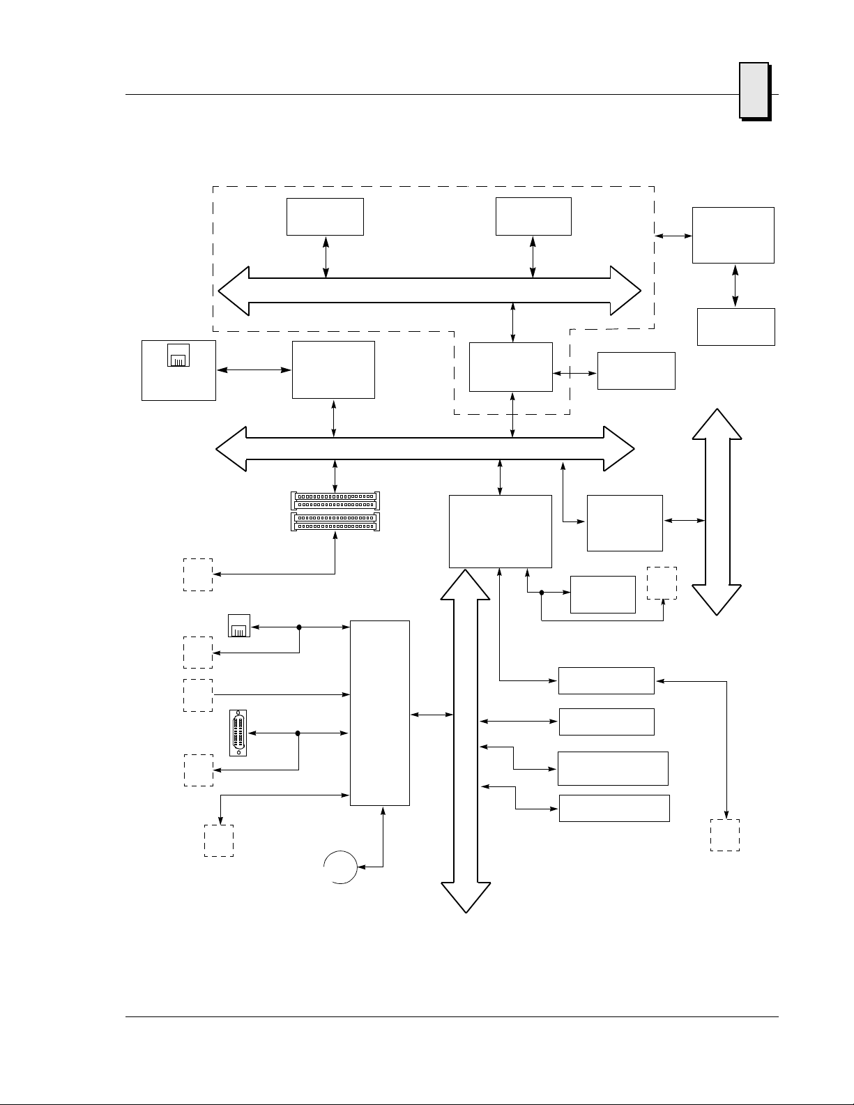
1
10BaseT
100BaseTx
J5
I/O
Front Panel RJ11
256 Kbyte
Cache
Ethernet
Controller
82559
Comm Port 1
Pentium II/Pentium III
Embedded Module
Host bus
PCI bus 0
PMC
Micro
Processor
North Bridge
System
Controller
South Bridge
PCI-to-ISA, IDE
Accelerator
(PIIX4E)
PCI-to-PCI
Bridge
DEC 21154
(Front Panel)
USB
DRAM
AGP
J3
69000 AGP
Video
Controller
Video
Connection
C
P
C
I
b
u
s
J3
J3
J3
Comm Port 2
Parallel Port
Floppy Drive
J3
PS/2 Keyboard/Mouse
Super
I/O
with
RTC
SMC
FDC37C67X
Figure 1-1 VMICPCI-7611 Block Diagram
I
PCI-to-EIDE
S
A
b
u
s
Flash BIOS
Watchdog Timer
DiskOnChip Flash
(Optional)
1284
J3
21
Artisan Technology Group - Quality Instrumentation ... Guaranteed | (888) 88-SOURCE | www.artisantg.com

1
VMICPCI-7611 Product Manual
CompactPCI Features
In addition to its PC/AT functions, the VMICPCI-7611 has the following CompactPCI
features:
• Single-slot, 6U height CPCI board
• C omplies fully with Revision 2.1 of the PCI Local Bus Specification
• C omplies fully with Revision 1.1 of the PCI-to-PCI Bridge Architecture
Specification
• Complies with Revision 2.1 of the CompactPCI Specification
• Implements delayed transactions for all PCI configuration, I/O, and memory
read commands-up to three transactions simultaneously in each direction
• Allows 152 bytes of buffering (data and address) for upstream posted memory
write commands and 88 bytes of buffering for downstream posted memory
write commands- up to nine upstream and five downstream posted write
transactions simultaneously
• Allows 152 bytes of read data buffering upstream and 72 bytes of read data
buffering downstream
• Provides concurrent primary and secondary bus operation to isolate traffic
• Provides enhanced address decoding
• Includes addressing and VGA palette snooping support
• Supports PCI transaction forwarding for the following commands
- All I/O and memory commands
- Type 1 to Type 1 configuration commands
- Type 1 to Type 0 configuration commands (downstream only)
- All Type 1 to special cycle configuration comman ds
• Includes downstream lock support
• S upports both 5 and 3.3 V signaling environments
The VMICPCI-7611 is a versatile single-board solution for CPCI control with familiar
PC/AT operation.
22
Artisan Technology Group - Quality Instrumentation ... Guaranteed | (888) 88-SOURCE | www.artisantg.com

VMICPCI-7611 Product Options
VMIC’s VMICPCI-7611 is built around three fundamental hardware configurations.
These involve processor power, RAM memory, and the optional DiskOnChip flash
memory size. These options are subject to change based on emerging technologies and
availability of vendor configurations.
VMICPCI-7611 Product Options
1
Artisan Technology Group - Quality Instrumentation ... Guaranteed | (888) 88-SOURCE | www.artisantg.com
23

1
VMICPCI-7611 Product Manual
24
Artisan Technology Group - Quality Instrumentation ... Guaranteed | (888) 88-SOURCE | www.artisantg.com

Installation and Setup
Contents
Unpacking Procedures . . . . . . . . . . . . . . . . . . . . . . . . . . . . . . . . . . . . . . . . . . . . . . . 3-25
Hardware Setup . . . . . . . . . . . . . . . . . . . . . . . . . . . . . . . . . . . . . . . . . . . . . . . . . . . . 3-26
Installation . . . . . . . . . . . . . . . . . . . . . . . . . . . . . . . . . . . . . . . . . . . . . . . . . . . . . . . . . 3-31
CHAPTER
2
Introduction
This chapter describes the hardware jumper settings, connector descriptions,
installation, system setup, and operation of the VMICPCI-7611.
Unpacking Procedures
Any precautions found in the shipping container should be observed. All items
should be carefully unpacked and thoroughly inspected for damage that might have
occurred during shipment. The board(s) should be checked for broken components,
damaged printed circuit board(s), heat damage, and other visible contamination. All
claims arising from shipping damage should be filed with the carrier and a complete
report sent to VMIC Customer Service together with a request for advice concerning
the disposition of the damaged item(s).
CAUTION: Some of the components assembled on VMIC’s products may be sensitive
to electrostatic discharge and damage may occur on boards that are subjected to a
high energy electrostatic field. When the board is placed on a bench for configuring,
etc., it is suggested that conductive material be inserted under the board to provide a
conductive shunt. Unused boards should be stored in the same protective boxes in
which they were shipped.
Artisan Technology Group - Quality Instrumentation ... Guaranteed | (888) 88-SOURCE | www.artisantg.com
25

2
VMICPCI-7611 Product Manual
Hardware Setup
The VMICPCI-7611 is factory populated with user-specified options as part of the
VMICPCI-7611 ordering information. The CPU speed, RAM size, and flash memory
size are not user-upgradable. To change CPU speeds, RAM/flash size, contact
customer service to receive a Return Material Authorization (RMA).
The VMICPCI-7611 is tested for system operation and shipped with factory-installed
header jumpers. The physical location of the jumpers and connectors for the single
board CPU are illustrated in Figure 2-1 on page 27. The definitions of the CPU board
jumpers and connectors are included in Table 2-1 through Table 2-10.
CAUTION: All jumpers are factory configured and should not be modified by the
user. There are two exceptions: the Password Clear (E3), and the Watchdog Timer
(E7). Modifying any other jumper will void the Warranty and may damage the unit.
The default jumper condition of the VMICPCI-7611 is expressed in Table 2-1 through
Table 2-10 with bold text in the table cells.
VMIC Customer Service is available at: 1-800-240-7782.
26
Artisan Technology Group - Quality Instrumentation ... Guaranteed | (888) 88-SOURCE | www.artisantg.com
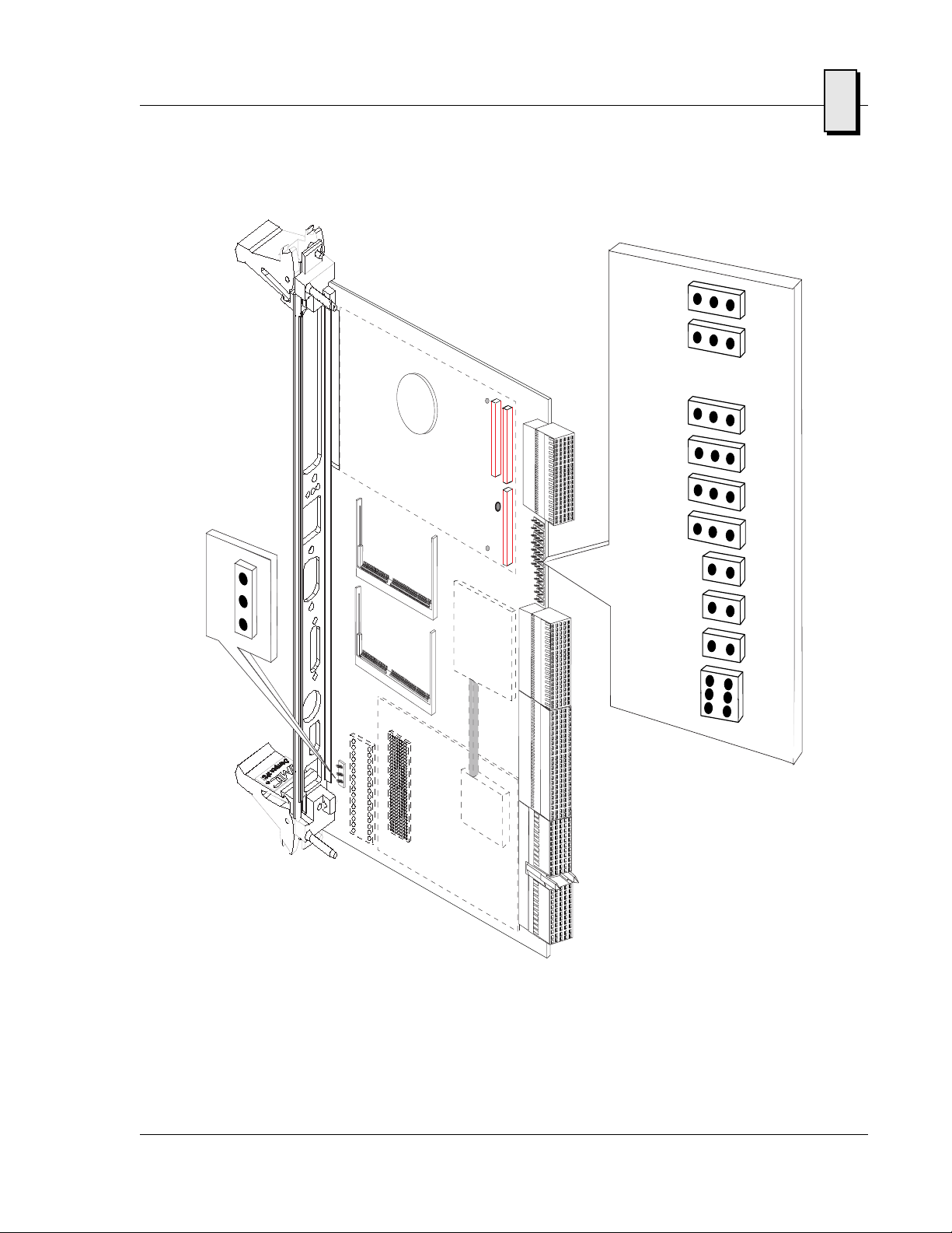
E12 E13E17E7 E8E18
Hardware Setup
2
E2
E10E6E3
E19
Figure 2-1 VMICPCI-7611 Embedded Module, and Jumper Locations
Artisan Technology Group - Quality Instrumentation ... Guaranteed | (888) 88-SOURCE | www.artisantg.com
27
2
VMICPCI-7611 Product Manual
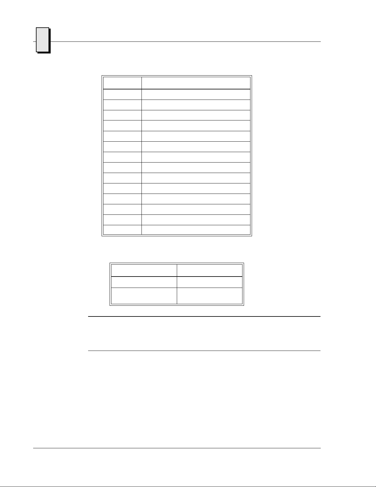
Table 2-1 CPU Board Connectors
Connector Function
J10 Mouse/Keyboard Connector
J9 USB Connector
J13 COM1
J3 COM1/COM2
J3, P2 Parallel Port Connector
J14 Ethernet Connector
J11 Video Connector
J3 Floppy Interface Connector
E15 ITP Test Header
E16 Port 80 Test Header
J3 EIDE Connector
E2 Fan Connector
J6, J7, J4 PMC Slot
J1, J2 Compact PCI Connectors
Table 2-2 Password Clear (User Configurable) - Jumper (E3)
Jumper Position
Normal Out
Clear NVRAM/CMOS/
Password
In
NOTE: The BIOS has the capability (not currently enabled) of password protecting
casual access to the unit’s CMOS set-up screens. The Password Clear jumper allows
for a means to clear the password feature, this might be necessary to perform in the
case of a forgotten password.
To clear the CMOS password:
1. Turn off power to the unit
2. Install a jumper at E3
3. Power up the unit
28
4. Turn off the power to the unit and remove the jumper from E3
When power is reapplied to the unit, the CMOS password will be cleared.
Artisan Technology Group - Quality Instrumentation ... Guaranteed | (888) 88-SOURCE | www.artisantg.com
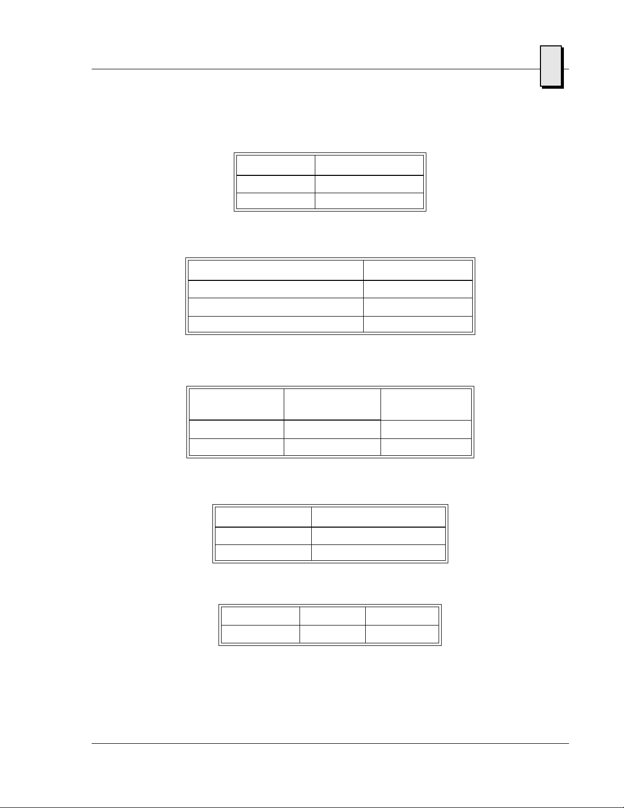
Table 2-3 Factory Configured - PIlX4E Battery Jumper (E6)
PIIX4E Battery Jumper Position
Enabled In
Disabled Out
Table 2-4 Factory Configured - Watchdog Timer jumper (E7)
Select Jumper Position
Watchdog Timer Reset 1-2
No Watchdog Timer Reset or SERR# Out
Watchdog Timer SERR# 2-3
Hardware Setup
2
Table 2-5 Factory Configured - Clock Speed Select Jumper (E8)
CPU Bus Frequency
(MHz)
PCI Bus
Frequency (MHz)
E8 Position
66.6 33.3 2-3
100 25 1-2
Table 2-6 Factory Configured - Watchdog Battery Jumper (E10)
SRAM Battery Jumper Position
Enabled In
Disabled Out
Table 2-7 Factory Configured - Reserved Jumper (E12)
Reserved 1 - 2 Out
Reserved 2 - 3 Out
Artisan Technology Group - Quality Instrumentation ... Guaranteed | (888) 88-SOURCE | www.artisantg.com
29
 Loading...