

VMI VIBER-A User Manual

VMI AB
Torsgatan 1
S-603 63 Norrköping, Sweden
Tel. 011-311667 / 311668
Fax. 011-311678
e-mail: vmiab@telia.com
www.vmi-instrument.se
A
uthorised distribut
o
VIBER-A
Manual

Page 2

Page 3
Warranty disclaimer
VMI AB warrants the products to be free from defects in material and
workmanship under normal use and service within two years from
the date of purchase and which from our examination shall disclose
to our reasonable satisfaction to be defective.
Warranty claimed products shall be returned prepaid to VMI AB for
service. We reserve the right to repair or to replace defective
products.
Always try to explain the nature of any service problem. At best by
fax, e-mail or letter. Check first all natural problems, like empty
batteries, broken cables, etc. When returning the product, be sure to
indicate that the purpose is to make repairs and indicate the original
date of shipment to you if possible.
General
The VIBER-A is a fully portable broadband vibrometer used in
preventive as well as active maintenance work on rotating
machinery. A complete set comprises an instrument, a vibration
transducer with magnet support and an extension tip.
VIBER-A is measuring the effective velocity (mm/s RMS)
(displacement (µm Peak) or in/s is option) in the frequency range
between 10 and 3200 Hz. This range covers most of the frequencies
that will occur for the majority of mechanical malfunctions and
imperfections. Examples are unbalance, misalignment of shafts and
gears, cavitation and other fluid generated vibrations.
The judgement of the measured levels is greatly supported by
several vibration standards. The close comparison between vibration
levels and actual wear being performed on the machinery will quickly
build up a local knowledge. The experience should be used to
optimise the type of action required when higher vibrations are
found.
A common standard for judgement of vibrations is ISO 10816-3 and
may be available from your domestic standardisation authority. This
standard is an upgrade of older standards that has been in use for
several decades and has a world wide acceptance as a good
judgement for continuos and long lasting operation of machinery. It is
rare that this standard is found to be too restrictive so any reason to
judge vibration with a less exacting judgement should be well backed
by practical experience.
Page 4
Functions
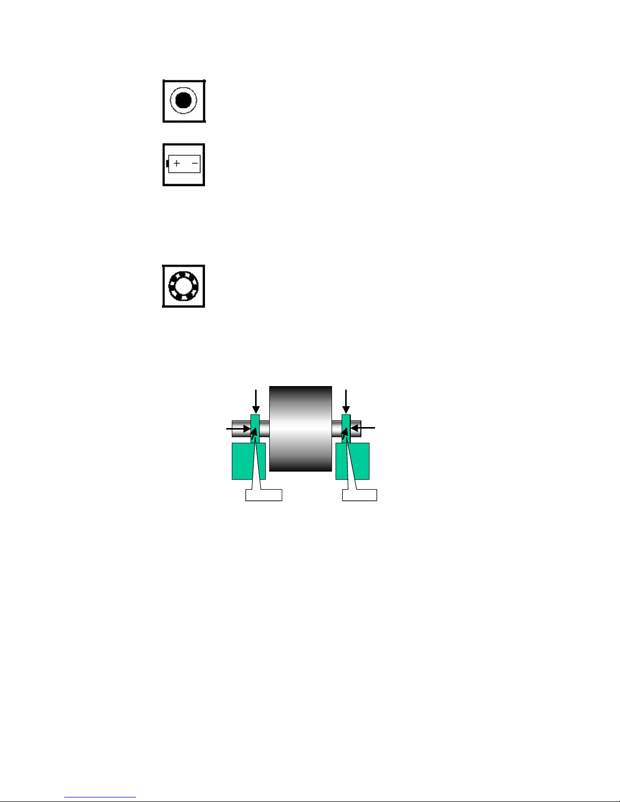
Start of the instrument
Press this symbol key and the instrument starts to
measure.
The instrument will be shut off automatically after
approximately 2,5 minutes.
Battery check
Press this symbol key and keep it pressed and the
instrument shows the battery voltage.
Change the battery when the voltage is below 7 volts.
The battery capacity of an ordinary type is enough for
approximately 20 hours of constant operation or 350
measurement.
The battery capacity of an alkaline type is enough for
approximately 40 hours of constant operation or 1000
measurement.
Bearing condition
Press this symbol key and keep it pressed. The
instrument measures instantaneously a bearing condition
value in the range between 3.200Hz to 20.000Hz.
Placing of the measuring point.
The measurements should be taken on or as close to the bearing as
possible and only in horizontal, vertical and axial directions.
Bearing
Bearing
V
H
H
V
A
A

Page 5
How to make good measurements.
The sensitivity direction of the transducer coincides with the centre
axis of the transducer. The transducer end (with the M6 stud) is
pushed firmly against the measurement point. The main purpose is
to make the complete transducer to fully participate in the motion of
the measurement point. Try to hold the transducer in a vertical,
horizontal or axial direction as possible, even if the machine surface
does not have these directions. Read the instrument held with the
free hand. Note a stable reading as well as a fluctuating one, since
the fluctuation itself is a valuable information regarding the reason for
the vibration.
When the transducer is mounted with the magnet the frequency
range of the measurement is reduced to about 2.000 to 3.000Hz
depending on the flatness of the measuring surface.
When the measuring tip is used the frequency range is reduced to
about 800 to 1500Hz.
Note
When using the magnet or the measuring tip the bearing condition
value can be substantially changed. Use the M6 stud on the
transducer for high frequency measurements.
Vibrations at high frequencies can sometimes cause measurement
problems. Pressing the transducer more firmly should not change the
reading. If in doubt, always try to adjust the contact point first.
Secondly, if shown to be necessary, mount the transducer with the
M6 stud.
All normal measurements on vertical or horizontal machinery should
follow the three perpendicular axis of true vertical, horizontal and
axial directions. The reason is that you should keep to the main
stiffness directions caused by normal non symmetrical properties of
the foundation, piping, supports etc. It will result in better
understanding if the basic measurements are made in this way.

Page 6
The VIBER-A is mainly intended for measurements against the
housing and bearings of machinery according to the intentions
of the standards. You can also use it to measure other parts
such as piping, valves, etc. Note that in some cases the mass of
the transducer may influence the reading. A good rule is to
consider readings on surfaces that are lower in mass than 10
times the mass of the transducer doubtful.
How to interpret vibration measurements.
A user with no previous experience to interpret the results is
recommended to use the ISO 10816-3 standard together with a good
portion of common sense.
Be prepared to find exemptions making the judgements harder than
the standards, rather than finding exemptions allowing for higher
vibrations.
The standard normally calls for a measure in velocity based on mm/s
RMS. To better understand what this measure means it can be
helpful to consider the reading as a mean value of the back and
forward motion. This measure gives a good understanding of the
amount of "break down energy", causing mainly wear and fatigue
work, in the machine or the structure being measured.
The instrument is measuring the total RMS-value of the vibration
within the instrument frequency range. This RMS-value is a special
sum or average of all the different causes of vibration.
EXAMPLE:
If the simultaneous vibration caused by unbalance is (4mm/s), by
misalignment (2 mm/s) and by the gearmesh (5 mm/s) then the total
vibration measured on the VIBER-A is 6.7 mm/s.
Total vibration =
Page 7
The ISO standard is classifying the machines differently if the
machines are considered as flexible or rigid mounted. This reflects
the location of the machines stiff-body resonance’s related to the
basic running speed of the machine.
For instance, a machine supported by rubber or springs often have
resonance’s at low running speeds. The machine starts vibrate at
certain low rpm. When the speed is increased above these
resonance frequencies the vibration is reduced. This machine is
considered flexible.
A resonance can easily be found when a flexible machine is running
up or down in speed. The resonance’s are located at the rpm´s
where the vibration have a local maximum level.
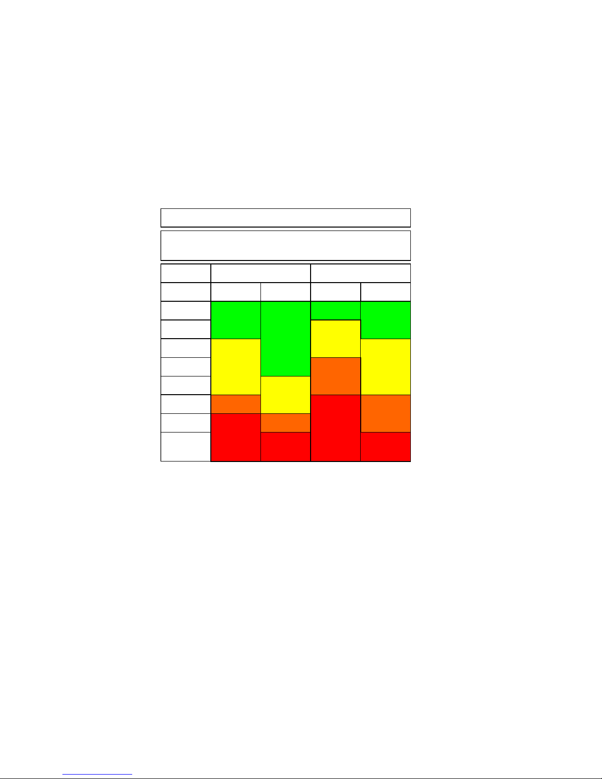
Rigid Flexible Rigid Flexible
Group 1 and 3 Group 2 and 4
Industrial machines with power above 15kW and
nominal speeds between120 -15000 r/min
mm/s
Unit
0-1.4
1.4-2.3
2.3-2.8
2.8-3.5
3.5-4.5
4.5-7.1
7.1-11
11--
Extraction's from ISO 10816-3
 Loading...