

Page 1
USA
GBE
D
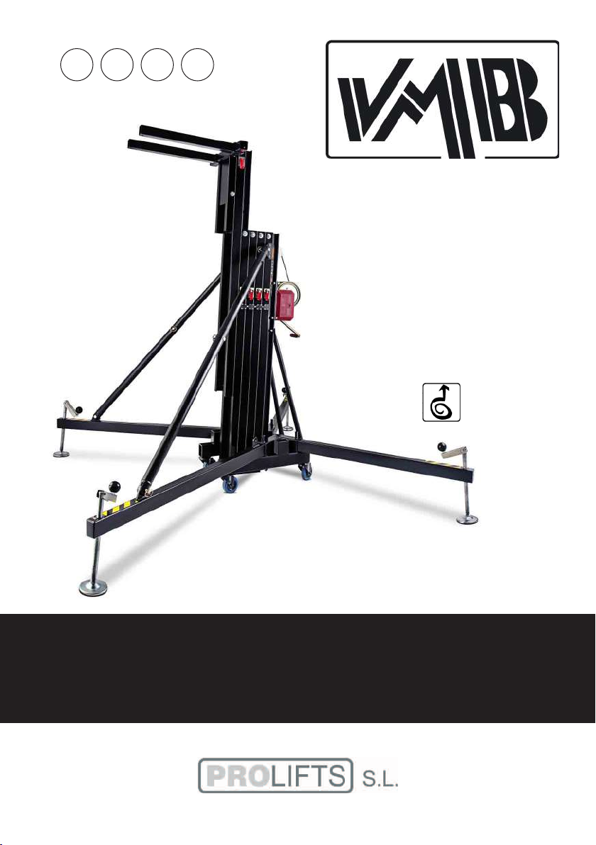
TL-A300
LINE ARRAY
TOWERLIFT
TORRE ELEVADORA
TRAVERSENLIFT
OPERATING INSTRUCTIONS USER MANUAL
MANUAL DE INSTRUCCIONES
V.05.19
Page 2
LIFTING TOWER TL-A300
TORRE ELEVADORA TL-A300
TRAVERSENLIFT TL-A300
CONTENTS / ÍNDICE
Features of the TL-A300 Towerlift / Características TL-A300............. 3 - 4
English Quick operation guide.................................................................... 5 - 11
Manual de usuario Español.......................................................................... 12 - 19
Bedienungsanleitung Deutsch.................................................................... 20 - 26
Sketches / Planos piezas................................................................................ 27 - 34
Spare part list / Lista de repuestos.............................................................. 35 - 37
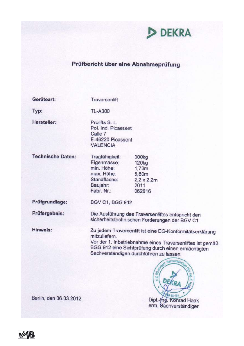
Certifications / Certificaciones...................................................................... 38
BGV-C1
BGG-912
EC Conformity Declaration pursuant to the EC Machinery Directives 89/392/CE and
98/37/CE: Manual lifters
Find a copy of the certications at the end of this booklet.
Puede ver una copia de las certicaciones al nal del manual.
MADE IN SPAIN (EU)
Manufacturer - Fabricante
PRO LIFTS S.L.
C/ Ciudad de Barcelona Nº19
Pol.Ind. Fuente del Jarro
46988 Paterna (Valencia)
Tlf Export: +34 96 171 81 86
Tlf Nacional: 96 171 81 83
[email protected] - www.prolifts.es
Este manual de usuario y catálogo anexo de piezas de repuesto es propiedad de PRO LIFTS S.L.
Queda prohibida su reproducción total o parcial por cualquier medio que la tecnología actual permita.
Deposito legal y copyright 2014. Todos los derechos reservados.
Page 3
F
TL-A300
W
N
2
A
S
V
T
T
V
E
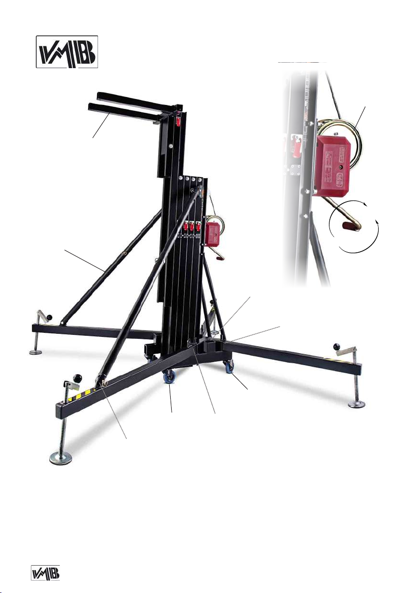
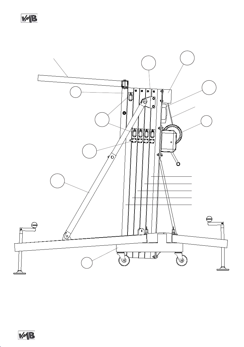
A: Reinforcement struts for line array / Refuerzo especial para Line Array
E: Anchor points for struts / Anclaje del tirante refuerzo frontal para Line Array
F: Load forks / Brazos de carga
N: Force on hand crank / Fuerza sobre manivela
S: Transport compartment for legs / Alojamiento de transporte para patas
T: Transport wheels / Ruedas de transporte
V: Working compartment for legs / Alojamiento de trabajo para patas
W: Winch / Cabrestante
N
1
Depósito legal y copyright. Todos los derechos reservados. 3PRO LIFTS S.L.
Page 4
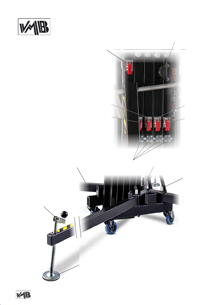
ALS-C: Auto Lock System carriage /
Gatillo automático carro
ALS-1: Auto Lock System 1st prole /
Gatillo automático tramo 1
ALS-2: Auto Lock System 2nd prole /
Gatillo automático tramo 2
ALS-3: Auto Lock System 3rd prole /
Gatillo automático tramo 3
ALS-4: Auto Lock System 4th prole /
Gatillo automático tramo 4
E: Anchor points for struts /
Anclaje del tirante de refuerzo frontal
H: Handle / Manivela
L: Spirit level
P: Leg / Pata
Q: Stabilizer / Estabilizador
SRS: Sequence Retainer System
R: Catch pawl / Gatillo bloqueo patas
ALS-C
ALS-3
ALS-4
TL-A300
E
ALS-2
ALS-1
H
P
Q
SRS
L
R
Depósito legal y copyright. Todos los derechos reservados. 4PRO LIFTS S.L.
Page 5
Quick operation guide
ENGLISH
CONTENTS
1. Introduction.
2. Technical information.
3. Safety precautions.
4. Operation.
5. Maintenance.
6. Guarantee.
1. INTRODUCTION
Dear customer, in order to ensure a safe
and reliable operation of the TL-A300
towerlift please follow the instructions in
this booklet carefully. Before operating the
lift, read the instructions completely and
please note the technical information contained within this manual.
All VMB products undergo very rigorous
testing, under strict conditions and they
are monitored continuously during the manufacturing process.
In order to guarantee the lifts function and
safety, only original parts from the manufacturer must be used. If any parts other
than those of the manufacturer are used,
or the product is modied in any way, the
user forfeits all warranty rights to claim.
VMB reserves the right to modify the pro-
duct specications without prior notice.
The model type, production year and serial number must be quoted in any queries
or orders for spare parts.
2. TECHNICAL INFORMATION
2.1 - TL-A300 Towerlift.
2.2 - Designed to lift audio systems, such
as PA systems or Line Array, up to different heights.
2.3 - Maximum load : 300 kg (662 lb).
2.4 - Minimum load: 25 Kg (55 lb).
2.5 - Security :
ALS (Automatic Lock System).
2.6 - Maximum height : 5.80 m (19’).
2.7 - Folded height : 1.58 m (5.2’).
2.8 - Transport surface:
0,62 x 0,48 x 1,58m (2.03 x 1.57 x 5.2’)
2.9 - Shipping dimension:
0,64 x 0,50 x 1,60m (2.10 x 1.64 x 5.25’)
2.10 - Work surface :
1.9 x 2.1 m (6.2’ x 6.9’).
2.11 - Unit weight : 165 Kg (364 lb).
2.12 - Load support:
Long forks (74.5 cm).
2.13 - Construction material : 6082-T6
alluminium for the main body, comprised
of 5 proles and a lifting carriage. Base
and legs are made of steel prole accor-
ding to DIN 2394. Catches and pulleys of
ST-37 steel.
2.14 - Winch: 1200 Kg. maximum load
with automatic brake. Certication CE and
GS TÜV.
Depósito legal y copyright. Todos los derechos reservados. 5PRO LIFTS S.L.
Page 6
Quick operation guide
ENGLISH
2.15 - Cable : Steel DIN 3060. Quality 180
2
Kg/mm
Cable diameter: Ø6 mm.
2.16 - Adjustable stabilizing feet with rubber non-slip supports.
2.17 - Safety catches to anchor the legs.
2.18 - Antirust protection, primed paint
twist resistant.
3. SAFETY PRECAUTIONS.
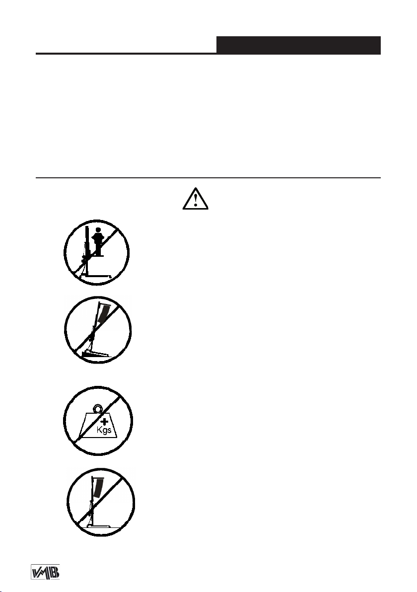
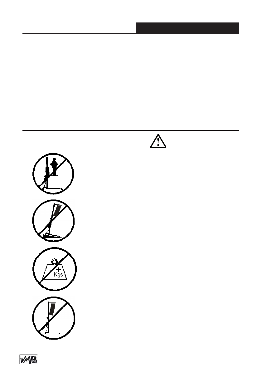
3.1 - The TL-A300 is a machine designed to elevate
loads upwards in a vertical direction, It should NEVER
be used as a platform to elevate people.
3.2 - Only place the lift on hard, at surfaces always
checking that it is in a vertical position by using the bub-
ble level indicator (L) found on the base. Adjust the leg
stabilizers (Q) by turning the handles (H) to level if necessary. NEVER use wedges or other foreign objects to
balance the lift.
with cured polyester dust cover. The tower
can be supplied with natural aluminium
nish or black (version B).
2.19 - Spirit level to adjust the tower vertically.
2.20 - Swivel wheels to transport the lift
when folded.
3.3 - The maximum load indicated on the characteristics
label and the instructions manual should not be exceeded.
3.4 - This lift should NEVER be used to elevate a load
that has not been properly checked. It is necessary to
verify that the load is correctly supported and centred
on the appropriate lift support so that the weight of the
load will only elevate in a vertical direction.
Depósito legal y copyright. Todos los derechos reservados. 6PRO LIFTS S.L.
Page 7
Quick operation guide
3.5 - Check that the legs (P) are placed and set-up correctly with their safety pins (R) inserted and locked.
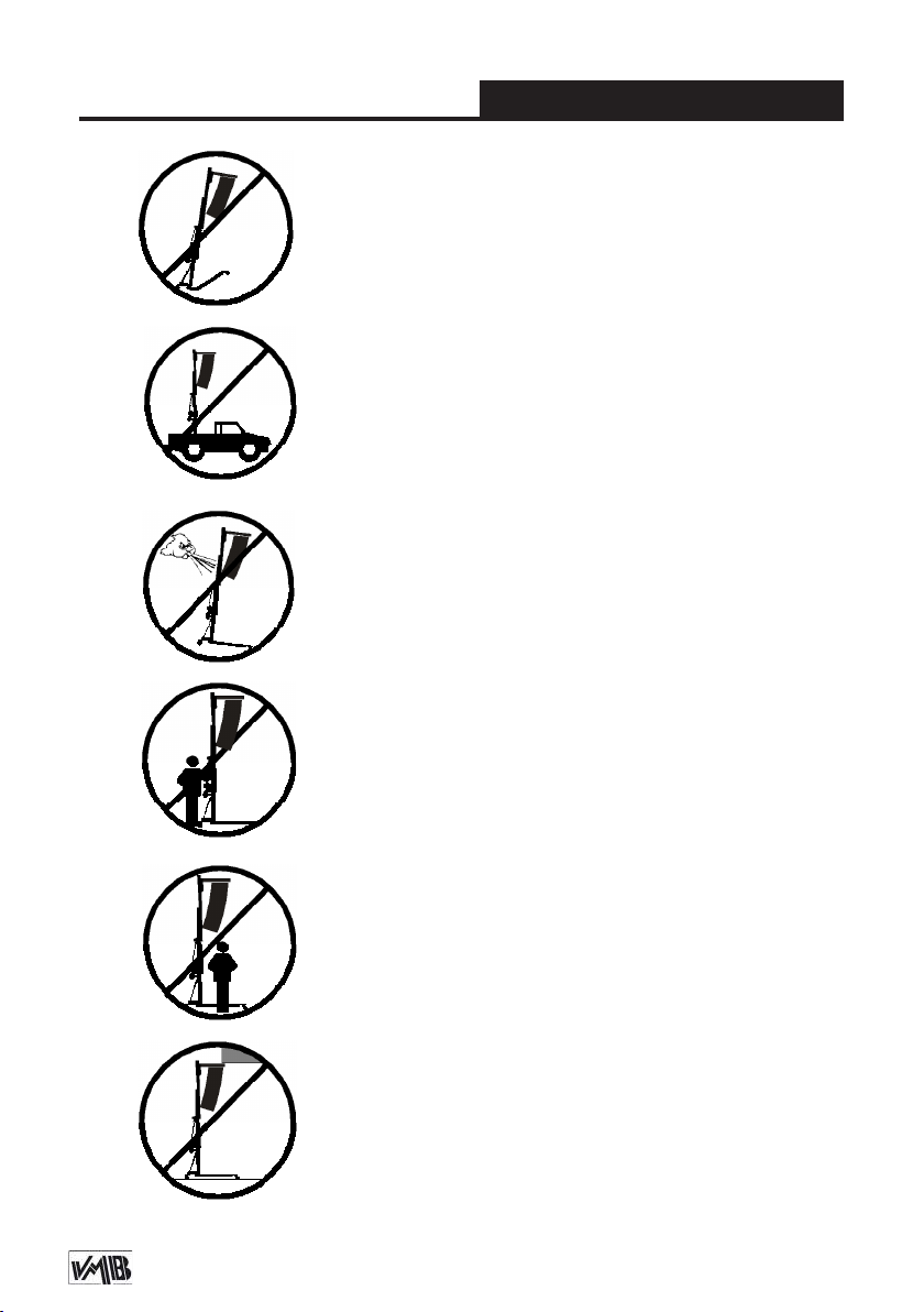
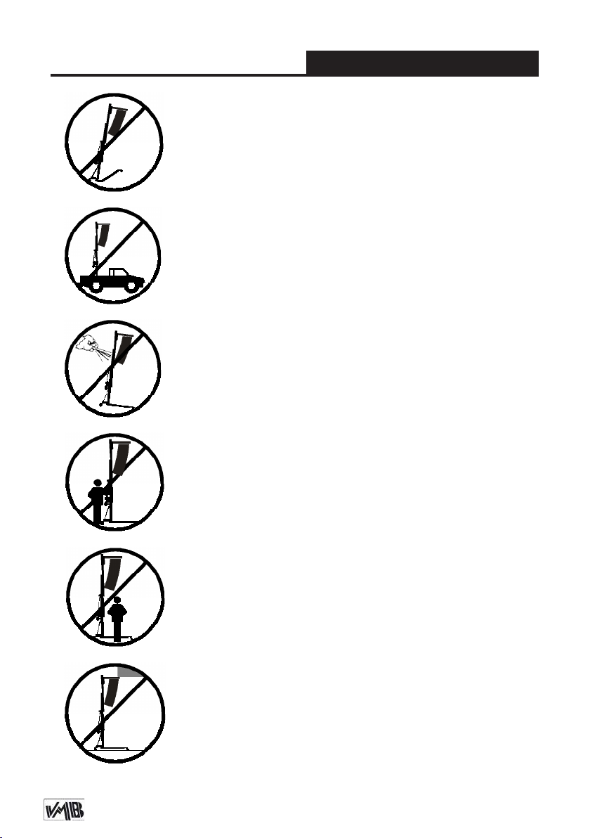
3.6 - NEVER use the lift on a vehicle or any other mobile
surface.
3.7 - If there is a possibility of strong winds or gusts,
place the lift on the ground rmly and secure it with the
use of straps. NEVER attach a strap to a vehicle or any
other object that can possibly be moved.
3.8 - NEVER move the lift whilst it is carrying a load. It
is not advisable to carry out any type of horizontal movement even small positional adjustments.
ENGLISH
3.9 - NEVER allow any team member below the load or
anybody else in the lifts operating zone.
3.10 - Take care with all obstacles above the lift and
its extension zone such as cornices, balconies, and
luminous signboards. It is very important to avoid the
presence of all types of cables below the extended lift.
Depósito legal y copyright. Todos los derechos reservados. 7PRO LIFTS S.L.
Page 8

Quick operation guide
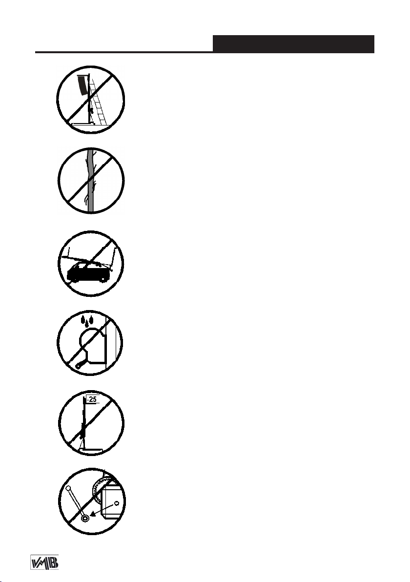
3.11 - Do not use stepladders on the lift or use it as a
support for them.
3.12 - Before using the lift, check the condition of the
cable. The cable should not have broken threads or
show any signs of crushed/attened areas. NEVER use
faulty cables, always change them if there is any doubt.
Only use VMB steel cables; reference: DIN 3060.
Quality: 180KG/mm and torsion resistant.
3.13 - All sections must be lowered rst, and the legs
placed in its transport position, before transportation.
3.14 - Do not grease or lubricate the winch’s braking
mechanism. The brake disks have been greased with
a special heat and pressure resistant solution. Other
products should not be used to avoid negative effects
regarding the braking mechanism.
ENGLISH
3.15 - The minimum load to avoid problems regarding
the braking mechanism is 25Kg. Without this load the
brake will not work.
3.16 - NEVER take apart the crank of the winch when
the lift is carrying a load or extended.
Depósito legal y copyright. Todos los derechos reservados. 8PRO LIFTS S.L.
Page 9
Quick operation guide
3.17 - Only original replacement parts should be used.
ORIGINAL
ENGLISH
4. USER INSTRUCTIONS.
4.1 - Place the lift on a rm, at surface
in the area it is to be used with the help of
the transport wheels (T).
4.2 - Remove the legs (P) from their trans-
port compartment (S) and fully insert them
into their working positions (V) checking
that they are xed by the pins (R). Remo-
ve the reinforcement struts (A) as well and
place them in their anchor points (E), x
them with their corresponding pins and
clips.
4.3 - Check that the lift is in vertical posi-
tion using the spirit level (L) at the base of
the tower, adjust the stabilizer (Q), turning
the handle (H) if necesary.
4.4 - Release the forks (F) and place them
in its working horizontal position ready to
take the load on them. Insert the pins to
block the forks.
4.5 - DO NOT OVERLOAD THE LIFT.
MAXIMUM LOAD IS 300 kg (662 lb)
The lift should NEVER be overloaded.
Safety at work is the most important issue. Place the load onto the lift using an
adequate VMB support according to the
need, use so that the weight of the load
will only be elevated in a vertical direction.
The minimum load is 25 Kg.
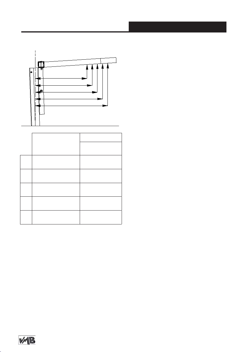
4.6 - How to place the load:
as close to the tower as possible.
The maximum load diminishes according
to the distance from the body of the tower
as illustrated in the diagram 4.6.1, which
shows the load on the gravity centre with
distances to the lifting carriage at a maximum lifting. Use a VMB adaptor if necessary.
CAUTION
When two towers are used to elevate a
truss bridge, or many towers to elevate a
structure of any type, it is almost impossible that two or more people co-ordinate
the winches elevating or lowering the
loads, at exactly the same pace. At a certain point each tower will be extended to
different height. For this reason it is necessary that the structure does not stretch
and allows for these differences.
With a rigid xation and if the level difference is signicant, the force generated
from the handle of the winch will deform
the structure and apply a lateral force to
the lifts causing them to break and block.
Always load
Depósito legal y copyright. Todos los derechos reservados. 9PRO LIFTS S.L.
Page 10
Quick operation guide
ENGLISH
Diagram 4.6.1
A
B
C
D
E
Distance from the
load’s center to the
axel of the tower
A
B
C
D
E
50 cm
(1.64’)
55 cm
(1.80’)
60 cm
(1.97’)
65 cm
(2.13’)
70 cm
(2.30’)
Maximum load
TL-A300
300 kg
(662 lb)
272 kg
(600 lb)
250 kg
(551 lb)
230 kg
(507 lb)
182 kg
(400 lb)
Security system ALS / ILS
The TL-A300 incorporates the patented
security system ALS (Automatic Lock
Security). This VMB red trigger system
automatically blocks the tower in the position it is left in. Each section of lift has
an ALS that blocks the section in the unlikely event of the cable breaking. For a
more complete security the lifting carriage
incorporates the ILS system (Inertial Lock
Security)
4.7 - Elevation:
1
Turn the winch crank clockwise (N
) to lift
the carriage and proles. The ALS system enable the lift to rise and automati-
cally block the carriage and proles whilst
rising ensuring that it will never fall. This
enables the cable to be without any force
and means it is only used for the elevation
and descent of the lift. The SRS (Sequence-Retainer-System) will also ensure that
the proles rise in sequence, one after the
other.
4.8 - Hold:
The tower can be left in any intermediate
position if it is necessary. Just stop turning
the handle of the winch and gently turn it
2
in an anticlockwise direction (N
) to block
the last prole risen. The ALS lock will
take the pressure of the load and release
strain applied on the cable.
4.9 - Lowering:
To bring the lift down you need to rst turn
the winch handle slightly clockwise (N
1
and at the same time pull the red ALS
lock (ALS-1) out. This releases the bloc-
king systems. Then turn the handle anti-
2
clockwise (N
), whilst maintaining the ALS
lock pulled out until the prole has been
completely lowered. All red ALS locks
(ALS-2, ALS-3 , ALS-4 & ALS-C) should
be pulled out one by one whilst the handle
2
is turned anti-clockwise (N
) and the pro-
les are brought down, one by one.
)
Depósito legal y copyright. Todos los derechos reservados. 10PRO LIFTS S.L.
Page 11

Quick operation guide
ENGLISH
If you release your nger from the ALS
lock it will automatically block. In this
case, repeat the rst operation by turning
slightly clockwise (N
kwise (N
ALS lock out. It is necessary to completely
lower each prole before starting to lower
the next. DO NOT pull another red ALS
lock without having completely lowered
the previous prole.
4.10 - Transport:
For the transport of the tower is necessary
to fold the machine lowering every prole
completely. Once the towerlift is completely folded, place the legs and the struts
(A) in their transport compartment (S) located at the legs, then the lift will be ready
to be transported.
2
) whilst always pulling the red
1
) and then anti-cloc-
5. MAINTENANCE.
5.1 - Regularly check the state of the ca-
ble. If the cable has broken threads, or if
it shows any signs of crushed/attened
areas, it should be changed and replaced
immediately with a new one. Do not use
the lift if the cables are in bad condition.
Only use VMB steel cables reference: DIN
3060 torsion resistant.
5.2 - The lift is supplied from the factory
completely greased. However, it is recommended to periodically grease according
to use, the gearing, the axis bearings, the
spiral of the crank, and the sections.
5.3 - All lifts should undergo an annual
technical inspection carried out by an
authorized VMB dealer to check the certications and general condition of all the
lift’s elements and security systems involved in the lift’s use.
5.4 - Only use original spare parts to guarantee a continued security level. The
user loses all rights to warranty if any spare parts other than originals are used or
carries out any modication or alteration
to the towerlift.
5.5 - To request a spare part please indicate the corresponding code which can
be found in this manual together with the
lift’s serial number and year of manufacture.
6. GUARANTEE.
The warranty period for this lift is 2 years
from the date of purchase.
PRO LIFTS S.L. promises, that from the
date of purchase and during the warranty
period to resolve any faults that may occur, produced through defect material or
fabrication. Damage caused by improper
use, product modication, third party manipulation or accidental re are not cove-
red by this warranty.
Depósito legal y copyright. Todos los derechos reservados. 11PRO LIFTS S.L.
Page 12

Manual de usuario
ESPAÑOL
CONTENIDO
1. Introducción.
2. Información técnica.
3. Precauciones de seguridad.
4. Instrucciones de uso.
5. Mantenimiento.
6. Garantía.
1. INTRODUCCIÓN
Estimado cliente: Con el n de garantizar
un funcionamiento seguro y able de la
torre elevadora TL-A300 por favor, siga
cuidadosamente las instrucciones de este
manual. Antes de manipular la torre elevadora, lea las instrucciones completas
y tenga en cuenta la información técnica contenida en este manual. Todos los
productos de VMB se someten a pruebas
muy rigurosas, en condiciones estrictas y
son monitorizados continuamente duran-
te el proceso de fabricación. Con el n de
garantizar el correcto funcionamiento y
seguridad de los elevadores, sólo deben
ser utilizadas piezas originales del fabricante. Si se utilizan piezas que no sean
las originales del fabricante, o el producto
se modica de alguna manera, el usuario
pierde todos los derechos de garantía.
VMB se reserva el derecho de modicar
las especicaciones y las piezas del pro-
ducto sin previo aviso. El tipo de modelo,
año de producción y el número de serie
deben ser citadas en cualquier consulta o
pedido de piezas de recambio.
2. INFORMACIÓN TÉCNICA
2.1 - Torre elevadora TL-A300.
2.2 - Diseñada para levantar sistemas de
audio, como sistemas de Line Array o PA,
en sentido vertical a diferentes alturas.
2.3 - Carga máxima: 300 kg (662 lb).
2.4 - Carga mínima: 25 Kg (55 lb).
2.5 - Seguridad: ALS (Sistema de gatillo
automático de seguridad).
2.6 - Altura máxima: 5.8 m (19’).
2.7 - Altura plegada: 1,58 m (5.2’).
2.8 - Dimensiones de la torre plegada:
0,62 x 0,48 x 1,58m (2.03 x 1.57 x 5.2’)
2.9 - Dimensiones de la caja transporte:
0,64 x 0,50 x 1,60m (2.10 x 1.64 x 5.25’)
2.10 - Área de la base:
1.9 x 2.1 m (6.2’ x 6.9’).
2.11 - Peso de la torre: 165 kg (364 lb).
2.12 - Soporte de carga:
Brazos de carga largos (74.5cm).
2.13 - Material de construcción: Cuerpo
principal de cinco tramos más carro ele-
vador en perl de aluminio extrusionado
6082-T6. Base, patas y soportes varios,
en perleria de acero según DIN 2394.
Gatillos de seguridad y poleas acanaladas en acero ST-37.
2.14 -
máxima con freno automático de retención
de la carga. Certicación CE y GS TÜV.
Cabrestante: 1200 kg de carga
Depósito legal y copyright. Todos los derechos reservados. 12PRO LIFTS S.L.
Page 13
Manual de usuario
ESPAÑOL
2.15 - Cable: Acero DIN 3060. Calidad de
2
resistencia a la torsión 180 kg/mm
Diámetro del cable: Ø6 mm.
2.16 - Patas estabilizadoras ajustables
con soportes de goma antideslizante.
2.17 - Gatillos de seguirdad para anclar
las patas.
2.18 - Protección anti-óxido, imprimación
.
3. PRECAUCIONES DE SEGURIDAD
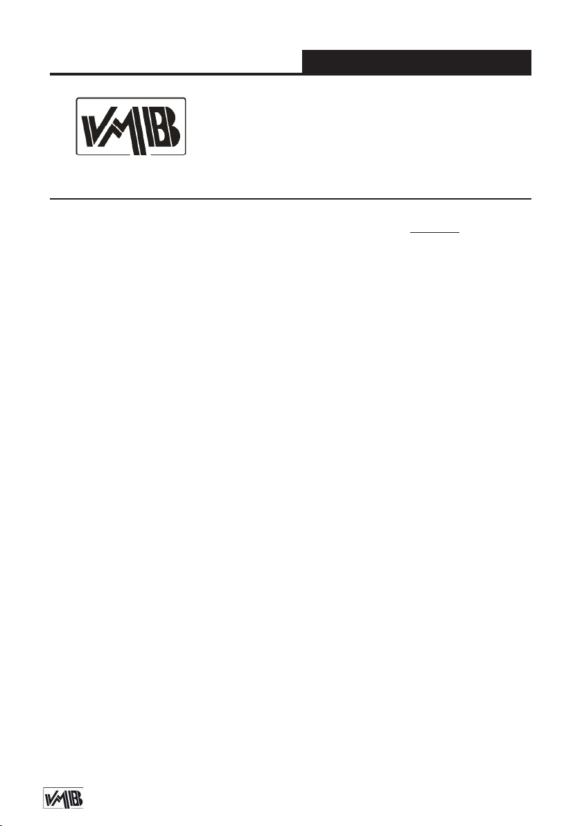
3.1 - La torre elevadora TL-A300 es una máquna diseñada
para la elevación de cargas en dirección vertical. NUNCA
se debe utilizar como plataforma eleavadora de personas.
3.2 - Colocar el elevador sólo en supercies rmes y planas,
vericando que está en posición vertical, utilizando el indi-
cador de nivel de burbuja (L) que se encuentra en la base.
Ajuste los estabilizadores (Q) girando las manivelas (H)
hasta nivelar, si es necesario. Nunca utilice cuñas u otros
objetos extraños para equilibrar el elevador.
con pintura de polvo poliester al horno. La
torre puede ser suministrada con acabado natural de aluminio o negro (versión
B).
2.19 - Nivel de burbuja para ajustar la verticalidad de la torre.
2.20 - Ruedas direccionales para el transporte de la torre cuando este plegada.
3.3 - La carga máxima indicada en las características técnicas mostradas en la etiqueta de la torre o en este manual
NO deben ser excedidas.
3.4 - Este elevador NUNCA debe utilizarse para elevar una
carga que no ha sido correctamente revisada. Es necesario
vericar que la carga está correctamente apoyada y centrada en el soporte de elevación apropiado para que el peso de
la carga sólo actúe en una dirección vertical.
Depósito legal y copyright. Todos los derechos reservados. 13PRO LIFTS S.L.
Page 14
Manual de usuario
3.5 - Comprobar que las patas (P) estén situadas correctamente, y jadas con los gatillos de seguridad (R) los cuales
deben estar introducidos y bloqueados.
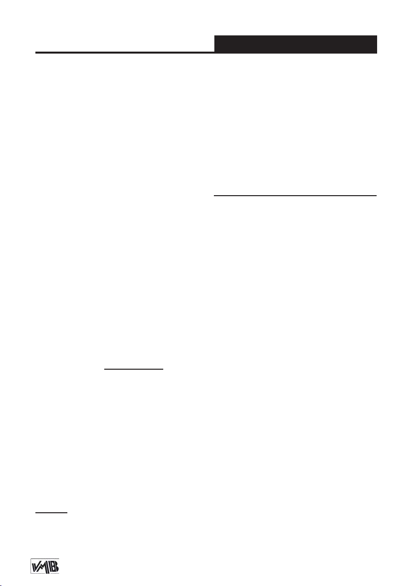
3.6 - NUNCA use el elevador sobre un vehículo o cualquier
supercie móvil.
3.7 - Si existe la posibilidad de vientos fuertes o ráfagas,
coloque el elevador en el suelo con rmeza y jelo mediante tirantes tensores. Nunca je un tirante a un vehículo o
cualquier otro objeto que se pueda mover.
3.8 - NUNCA mueva el elevador mientras esté cargado. No
es aconsejable llevar a cabo cualquier tipo de movimiento
horizontal, ni tan sólo pequeños ajustes de posición.
ESPAÑOL
3.9 - NUNCA permita que ningún miembro del equipo o
cualquier otra persona se sitúe debajo de la carga en la
zona de operación de las torres elevadoras.
3.10 - Tenga cuidado con todos los obstáculos por encima
de la elevación y su zona de extensión, como cornisas,
balcones, letreros luminosos, etc. Es muy importante evitar la presencia de todo tipo de cables por debajo de la
torre extendida.
Depósito legal y copyright. Todos los derechos reservados. 14PRO LIFTS S.L.
Page 15
Manual de usuario
3.11 - No usar escaleras encima del elevador ni utilizarlo
como un apoyo para éstas.
3.12 - Antes de utilizar el elevador, compruebe el estado
del cable. El cable no debe contener hilos rotos o mostrar
signos de áreas aplastadas/aplanadas.
NUNCA use cables defectuosos, siempre debe cambiarlos
si hay alguna duda. Utilice solamente cable de acero VMB
referencia: DIN 3060. Calidad: 180kg/mm y resistente a la
torsión.
3.13 - Antes de transportar la torre, todos los tramos deben
ser bajados, y las patas deben extraerse y colocarse en su
posición de transporte.
3.14 - No engrasar ni lubricar el mecanismo de freno del
cabestrante. Los discos de freno vienen engrasados con
una solución especial resistente a la presión y al calor. No
deben utilizarse otros productos, para evitar los efectos
negativos sobre el mecanismo de frenado.
ESPAÑOL
3.15 - La carga mínima para evitar problemas relaciona-
dos con el mecanismo de rotura es 25 kg. Sin esta carga
mínima el freno no funcionará.
3.16 - NUNCA desmontar la manivela del cabrestante
cuando el elevador está soportando una carga o extendido.
Depósito legal y copyright. Todos los derechos reservados. 15PRO LIFTS S.L.
Page 16
Manual de usuario
3.17 - Sólo deben ser utilizadas piezas de repuesto
originales de VMB PRO LIFTS S.L.
ORIGINAL
ESPAÑOL
4. INSTRUCCIONES DE USO.
4.1 - Coloque el elevador sobre una su-
percie rme y plana de la zona de trabajo sirviendose de las ruedas direccionales
de transporte (T).
4.2 - Extraiga las patas (P) de su aloja-
miento para transporte (S) e insertelas
totalmente en su posición de trabajo (V),
comprobando que los gatillos de seguridad (R) se insertan y jan la pata. Extrai-
ga también los tirantes de apoyo especial
(A) y coloquelos en su posición de sujección (E) asegurandolos con su pasador y
clip de seguridad.
4.3 - Compruebe que la torre esta en
posición vertical sirviendose del nivel de
burbuja (L) situado en el perl base, si es
necesario ajuste la vertical de la torre con
los estabilizadores (Q) de las patas, girando las manivelas (H).
4.4 - Libere los brazos de carga (F) y co-
loquelos en posición horizontal e inserte
los pasadores de seguridad con sus clips.
4.5 - LA CARGA MÁXIMA PARA
TL-A300 ES 300 kg (662 lb).
La torre elevadora NUNCA debe ser sobrecargada. La Seguridad en el Trabajo
es el elemento más importante. Coloque
la carga en el elevador mediante un soporte adecuado según la necesidad de
modo que el peso de la carga sólo actúe
en dirección vertical. La carga mínima
son 25 kg.
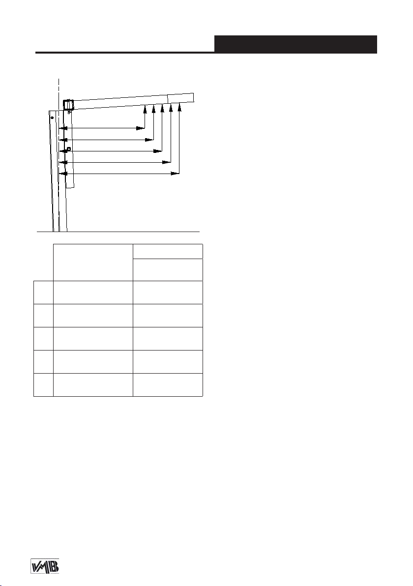
4.6 - Como colocar la carga:
Cargue siempre tan cerca de la torre
como pueda. La capacidad de carga de
la torre decrece cuanto más lejos este la
carga separada de la torre, como se ilustra en el esquema (4.6.1) de la siguiente
página. El cual muestra la carga en su
centro de gravedad con distancias al carro elevador que sostiene los brazos y a
máxima altura.
PRECAUCIÓN
Cuando se utilizan dos torres para elevar
un puente, descender truss o varias torres
para elevar una estructura de cualquier
tipo, es casi imposible que dos o más personas coordinen los cabrestantes exactamente a la misma velocidad al elevar o
bajar las cargas. En un momento determinado cada torre se elevará a una altura
Depósito legal y copyright. Todos los derechos reservados. 16PRO LIFTS S.L.
Page 17
Manual de usuario
A
B
C
D
E
Esquema 4.6.1
ESPAÑOL
Sistema de seguridad ALS / ILS
El TL-A300 incorpora el sistema de seguridad patentado ALS (bloqueo automático
de seguridad). Este sistema VMB de gatillo rojo bloquea automáticamente la torre
en la posición que se deja. Cada tramo
de elevación tiene un ALS que bloquea
el tramo en el caso improbable de que el
cable se rompa. Para aún más seguridad
el carro también incorpora el sistema ILS
de bloqueo de inercia.
Distancia del
centro de la carga
al eje de la torre
A
B
C
D
E
50 cm
(1.64’)
55 cm
(1.80’)
60 cm
(1.97’)
65 cm
(2.13’)
70 cm
(2.30’)
Carga Máxima
TL-A300
300 kg
(662 lb)
272 kg
(600 lb)
250 kg
(551 lb)
230 kg
(507 lb)
182 kg
(400 lb)
diferente a la de las demás. Por ello, es
necesario que la estructura no se estire y permita estas diferencias. Con una
jación rígida y si la diferencia de nivel es
importante, la fuerza generada a partir de
la manivela del cabrestante deformará la
estructura y aplicará una fuerza lateral a
los elevadores provocando su bloqueo y
ruptura.
4.7 - Elevación:
Gire la manivela del cabestrante en sen-
1
tido horario (N
) para elevar el carro y los
tramos. El sistema de gatillos ALS le permitirá elevar todos los tramos mientras
que estos se van bloqueando automáticamente, asegurando que la torre nunca
caerá. Esto hace que no actue ninguna
fuerza sobre el cable mientras la torre
esta parada, lo que signica que solo será
usado para elevar y descender la torre.
El sistema único SRS permite que los
perles se eleven de forma secuencial u
ordenada, uno detrás de otro.
4.8 - Bloqueo:
La torre puede dejarse en cualquier posición intermedia si se requiere. Una vez
el sistema esta elevado hasta la altura
deseada tan solo deje de girar la manivela y el freno automático del cabrestan-
Depósito legal y copyright. Todos los derechos reservados. 17PRO LIFTS S.L.
Page 18
Manual de usuario
ESPAÑOL
te bloqueará y sujetará la carga, en este
momento gire la manivela del cabrestante
2
en sentido anti-horario (N
) para bloquear
el último tramo con el gatillo ALS rojo. Los
gatillos tomarán la presión de la carga y
liberará la tensión aplicada al cable.
4.9 - Descenso:
Para descender la torre es necesario,
primero girar la manivela del cabrestan-
1
te ligeramente en sentido horario (N
)
para liberar el gatillo ALS rojo (ALS-1), a
continuación girar la manivela en sentido
2
anti-horario (N
) mientras se sigue tirando del gatillo ALS rojo (ALS-1), hasta que
el tramo esté completamente bajado. Todos los gatillos ALS rojos (
ALS-4 & ALS-C
) deben ser desbloquea-
ALS-2, ALS-3,
dos mientras se gira la manivela del ca-
2
brestante en sentido anti-horario (N
),
repita esta operación hasta descender
todos los perles de uno en uno.
Si en el proceso se quita el mano del ALS
se bloqueará automáticamente. En este
caso, repita la primera operación girando
ligeramente la manivela en sentido horario, desbloquando el ALS y siguiendo en
sentido anti-horario, mantener al tiempo
los ALS rojos desbloqueados. Debe descender completamente cada tramo antes
de empezar a bajar el siguiente.
NUNCA tire de otro ALS rojo sin haber
bajado completamente el tramo anterior.
4.7 - Transporte:
Para el transporte de la torre es necesario bajar completamente todos los tramos.
Una vez la torre haya sido plegada, coloque las patas y los tirantes de refuerzo
especial para Line Array en su alojamiento para transporte (S), y la torre ya estará
lista para su transporte.
5. MANTENIMIENTO
5.1 - Comprobar periódicamente el esta-
do del cable. Si en el cable existen hilos
rotos, o si muestra signos de zonas aplastadas/aplanadas, debe ser sustituido inmediatamente por uno nuevo. No use el
elevador si los cables están en mal estado. Utilice solamente cable de acero DIN
3060 resistente a la torsión.
5.2 - La torre elevadora es suministrada
de fábrica completamente engrasada.
Sin embargo, se recomienda un engrase
periódico, según el uso, de las ruedas de
fricción, los cojinetes de eje, la espiral de
la manivela, y los tramos.
RECUERDE: NUNCA engrasar ni lubricar
el mecanismo de freno. No es necesario
engrasar los discos de freno. Los discos
de freno vienen engrasados con una solución especial resistente a la presión y al
calor. No deben utilizarse otros productos,
para evitar los efectos negativos sobre el
Depósito legal y copyright. Todos los derechos reservados. 18PRO LIFTS S.L.
Page 19

Manual de usuario
ESPAÑOL
mecanismo de frenado.
5.3 - Todos los elevadores se someten a
una inspección técnica anual llevada a
cabo por un distribuidor autorizado VMB
para comprobar las certicaciones y el
estado general de todos los elementos de
elevación y sistemas de seguridad que intervienen en el uso del elevador.
5.4 - Utilice únicamente piezas de repuesto originales para garantizar el nivel de
seguridad de forma continuada. El usuario pierde todos los derechos de garantía
si las piezas de repuesto utilizadas no son
originales o se utilizan o se lleva a cabo
cualquier modicación o alteración de la
torre elevadora.
5.5 - Para solicitar una pieza de recambio indique el código correspondiente que
se encuentra en este manual junto con el
número de serie de la torre y el año de
fabricación.
que puedan producirse, debidos a material defectuoso o fabricación. Los daños
causados por un uso inadecuado, modi-
cación del producto, la manipulación de
terceros o incendio accidental no están
cubiertos por esta garantía.
6. GARANTÍA
El período de garantía para este elevador
es de 2 años a partir de la fecha de compra.
PRO LIFTS S.L. se compromete, que a
partir de la fecha de compra y durante el
período de garantía, a resolver los fallos
Depósito legal y copyright. Todos los derechos reservados. 19PRO LIFTS S.L.
Page 20

Bedienungsanleitung
DEUTSCH
INHALTSVERZEICHNIS
1. Einführung.
2. Technische Daten.
3. Sicherheitsmaßnahmen.
4. Bedienungsanleitung.
5. Wartung.
6. Garantie.
7. Zertikat.
1. EINFÜHRUNG
Sehr geehrte Damen und Herren,
die vorliegende Betriebsanleitung wurde
mit dem Zweck erstellt, eine zuverlässige
Bedienung des TL-A300 Hebeturms zu
ermöglichen. Lesen Sie bitte die Betriebsanleitung vor der Inbetriebnahme sor-
gfältig durch. Bitte beachten Sie auch die
technische Daten.
Unsere Produkte unterliegen strengsten
Prüfungen und Kontrollen bei der Fertigung.
Es sind ausschließlich Original-Ersatzteile
zu verwenden. Für den Anwender werden
alle Gewährleistungsansprüche aufgehoben, wenn er Nicht-Original-Ersatzeile
verwendet bzw. änderungen am Produkt
selbst vormimmt.
2. TECHNISCHE DATEN.
2.1 - Hebeturm, Typ TL-A300.
2.2 - Das Gerät ist zum senkrechten Heben
von Lasten, wie Beleuchtungskörper auf
verschiede Höhen, konzipiert worden.
2.3 - Zulässige Hubkraft: 300 kg (662 lb)
2.4 - Mindesthublast : 25 Kg.
2.5 - Zulässige Hubhöhe: 5.80 m (19’)
2.6 - Mindesthöhe: 1.58 m (5.2’)
2.7 - Gefaltete Dimensionen:
0,62 x 0,48 x 1,58m (2.03 x 1.57 x 5.2’)
2.8 - Abmessungen Box:
0,64 x 0,50 x 1,60m (2.10 x 1.64 x 5.25’)
2.9 - Grundplattenäche :
1.9 x 2.1 m (6.2’ x 6.9’).
2.10 - Transportgewicht: 165 kg (364 lb)
2.11 - Werkstoffe: Aluminium 6082-T6 Prol.
Basisplatte und Ausleger aus Stahlprol
DIN 2349. Verschlüsse aus ST-37 Stahl.
2.12 - Exklusive ALS System
( Pat. Pen. 200501056)
2.13 - Die Winde: 1200 kg.
2.14 - Seildurchmesser: Steel DIN 3060.
Qualität 180 kg/ mm
Durchmesser: Ø6 mm
2.15 - Ausleger mit verstellbaren Spindeln
und rutschfesten Gummifüßen.
2.16 - Verankerung der Ausleger über
Sicherheitsrastbolzen.
2.17 - Wasserwaage zum Einstellen der
senkrechten Turmlage.
2.18 - Korrosionsschutz und Veredelung
durch elektrolytische Cadmierung oder
(Version B) Satinpolyester. Erhältlich in
Natur Aluminium oder.
2.19 - Transportrollen zum Bewegen des
Turms bei senkrechter und eingefahrener
Stellung zur Arbeitsstelle.
2
(optional TL-A300)
Depósito legal y copyright. Todos los derechos reservados. 20PRO LIFTS S.L.
Page 21
Bedienungsanleitung
3. SICHERHEITSMAßNAHMEN.
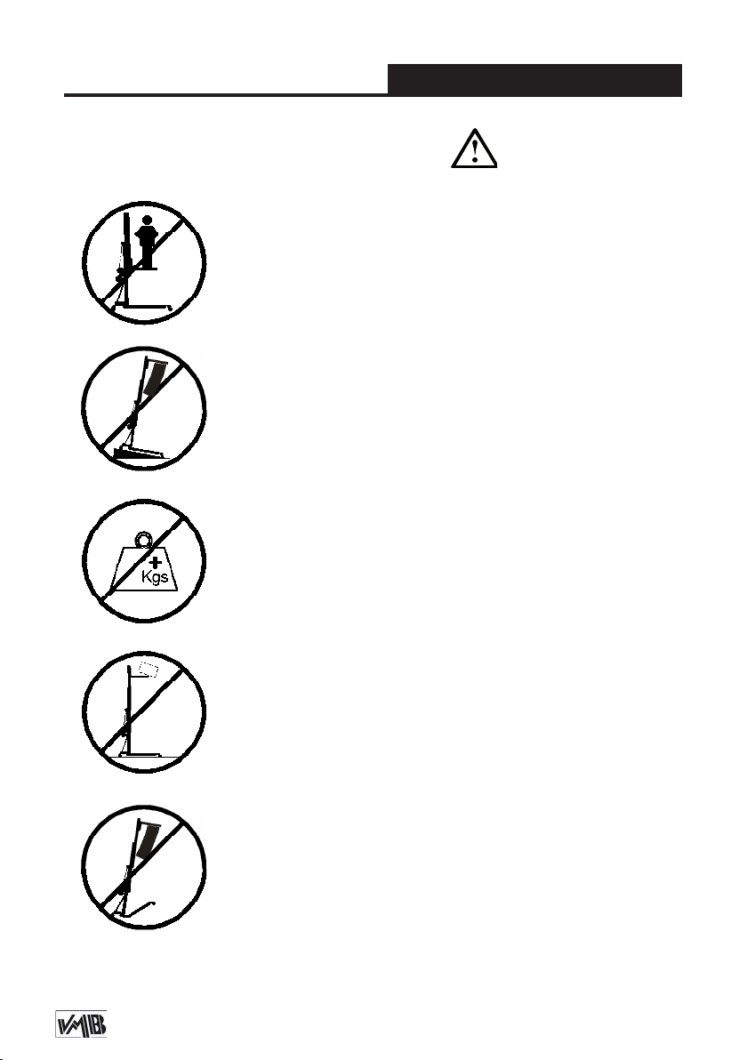
3.1 - Der TL-A300 wurde konzipiert zum Heben und Senken
von vertikalen Lasten. Nutzen Sie Ihn niemals zur Beförderung von Personen.
3.2 - Achten Sie darauf, das der TL-A300 Tower auf festem,
geraden Untergrund steht. Und vergewissern Sie sich mit Hilfe
der Wasserwaage (F), dass er eine vertikale Position zum
Boden eingenommen hat.Bei Bedarf mittels des Stelltellers
(Q) durch Drehen der Spindelkurbel (H) die entsprechende
Tunlage einstellen.
3.3 - Die zulässige Höchstlast, die Sie auf den Typenschild,
welche sie in der Bedienungsanleitung nden, darf niemals
überschritten werden
DEUTSCH
3.4 - Niemals sollten Sie eine ungesicherte Ladung heben.
Vergewissern Sie sich immer, das die Ladung zentriert auf
der Gabel auiegt und nur in vertikaler Richtung hebt!
3.5 - Vergewissern Sie sich, dass die Ausleger richtig ein-
gesteckt sind und nutzen Sie die Rastbolzen zum feststellen!
Depósito legal y copyright. Todos los derechos reservados. 21PRO LIFTS S.L.
Page 22
Bedienungsanleitung
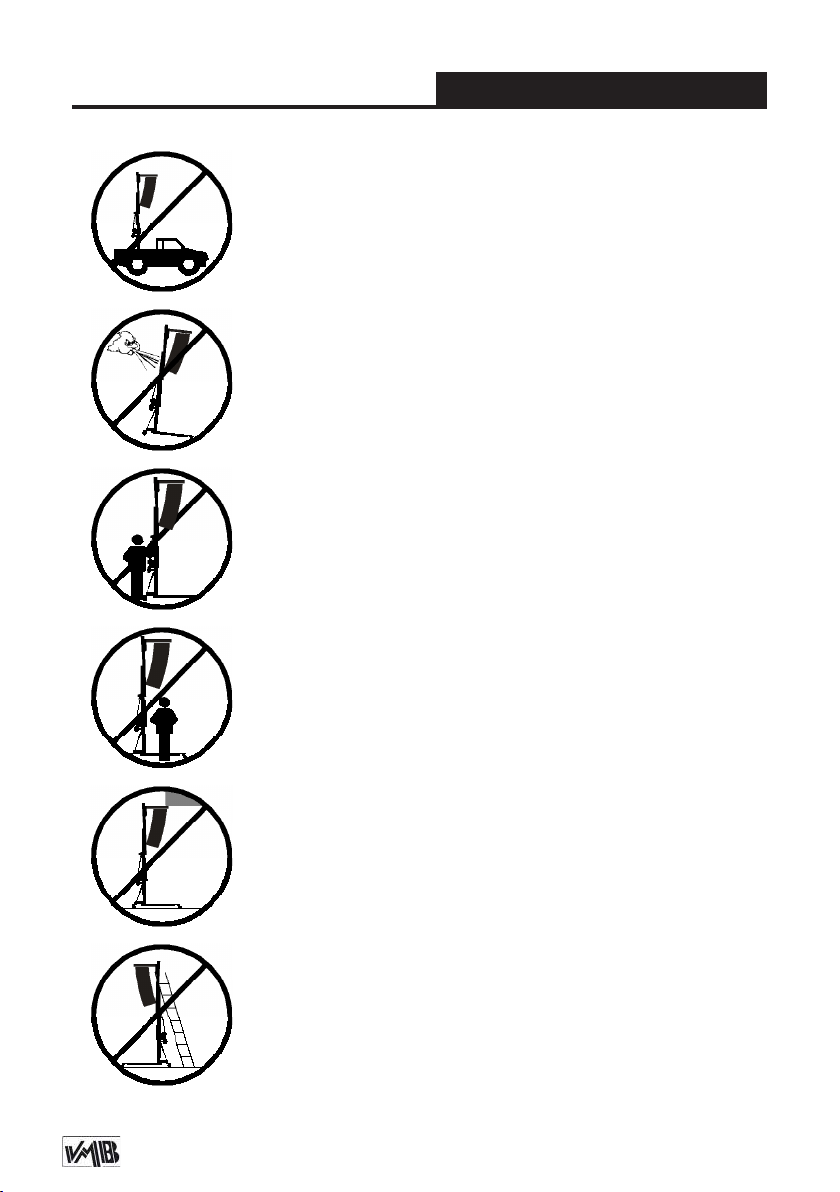
3.6 - Es ist nicht gestattet den Lift auf einem Fahrzeug mit
einen mobilen Unterbau zu installieren!
3.7 - Bei Freiluftanwendungen den Turm auf festen Boden
stellen und mittels Seilanker gegen Windbelastung sichern.
Niemals an Fahrzeugen die Abspannungen befestigen oder
an Gegenständen, die ausweichen könnten.
3.8 - Bewegen Sie den Lift niemals unter Belastung.
DEUTSCH
3.9 - Halten Sie sich niemals während des Hebens und
Senkens in Gefahrenbereich auf.
3.10 - Achten Sie auf alle Gegenstände im oberen Hubbereich des Liftes. Achten Sie auf Balkone, Leuchtschriften
und besonders auf stromführende Kabel.
3.11 - Stellen Sie niemals Leitern an den Tower.
Depósito legal y copyright. Todos los derechos reservados. 22PRO LIFTS S.L.
Page 23
Bedienungsanleitung
3.12 - Vor Gebrauch Seilzustand kontrollieren. Das Seil
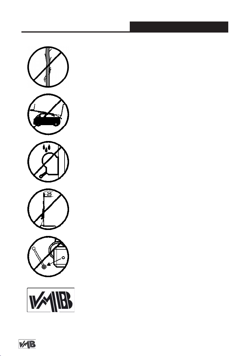
darf keine Seilbrüche oder Quetschungen aufweisen. Es
dürfen auf keinem Fall Seile in einem schlechten Zustand
verwendet werden.
3.13 - Alle Angebauten Teile sind für den Transport einzufahren.
3.14- Ölen oder Fetten der Fallbremsen ist zu unterlassen,
da diese mit einem Druck und Hitzebeständigen Material
bearbeitet wurden. Andere Werkstoffe führen in der Handhabung zu negativen Effekten.
DEUTSCH
ORIGINAL
3.15 - Die maximale Belastung zur Überprüfung der Si-
cherungen ist 50 kg. Ohne Belastung ist die Überprüfung
nicht möglich.
3.16 - Niemals die Winde, oder Teile der Winde unter Belastung demontieren.
3.17 - Es sind ausschließlich Original Ersatzteile zu verwenden. Für den Anwender werden alle Gewährleistungsansprüche aufgehoben, wenn nicht Original Ersatzteile verendet
bzw.Änderungen an Produkten vorgenommen werden.
Depósito legal y copyright. Todos los derechos reservados. 23PRO LIFTS S.L.
Page 24
Bedienungsanleitung
4. Bedienungsanleitung.
4.1 - Den Hebeturm auf den Transportrollen
( T ) abgestützt auf eine ebene und feste
Fläche an der Arbeitsstelle aufstellen.
4.2 - Die Ausleger (P) aus der Transporhalterung (S) herausnehmen und in deren
Arbeitsaufnahmen (V) voll einschieben.
Dabei achten Sie bitte darauf, daß sie mittels
der Sicherheitsbolzen (R) befestigt sind.
4.3 - Die senkrechte Turmlage über die
verstellbaren Stellteller ( Q ) durch Drehen
der Kurbel ( H ) in entsprechender Richtung
zum Zentrieren der Wasserwaagenblase (
F ) an der Kreismitte einstellen.
4.4 - Die Sicherheitsbolzen ( L ) der Lastau-
fnahmeausleger entfernen, die Ausleger zur
Lastaufnahme ( U ) in einer waagerechten
Position bringen und die Sicherheitsbolzen
wieder anbringen.
4.5 - Die zu hebende Last auf dem Turm
mittels eines geeigneten Trägers so aufstellen, dass das Lastgewicht nur senkrecht
wirkt. Die maximale Last von 240 kg darf
nie überschritten werden.
4.6 - Plazieren der Ladung:
Plazieren Sie die Ladung so nah wie
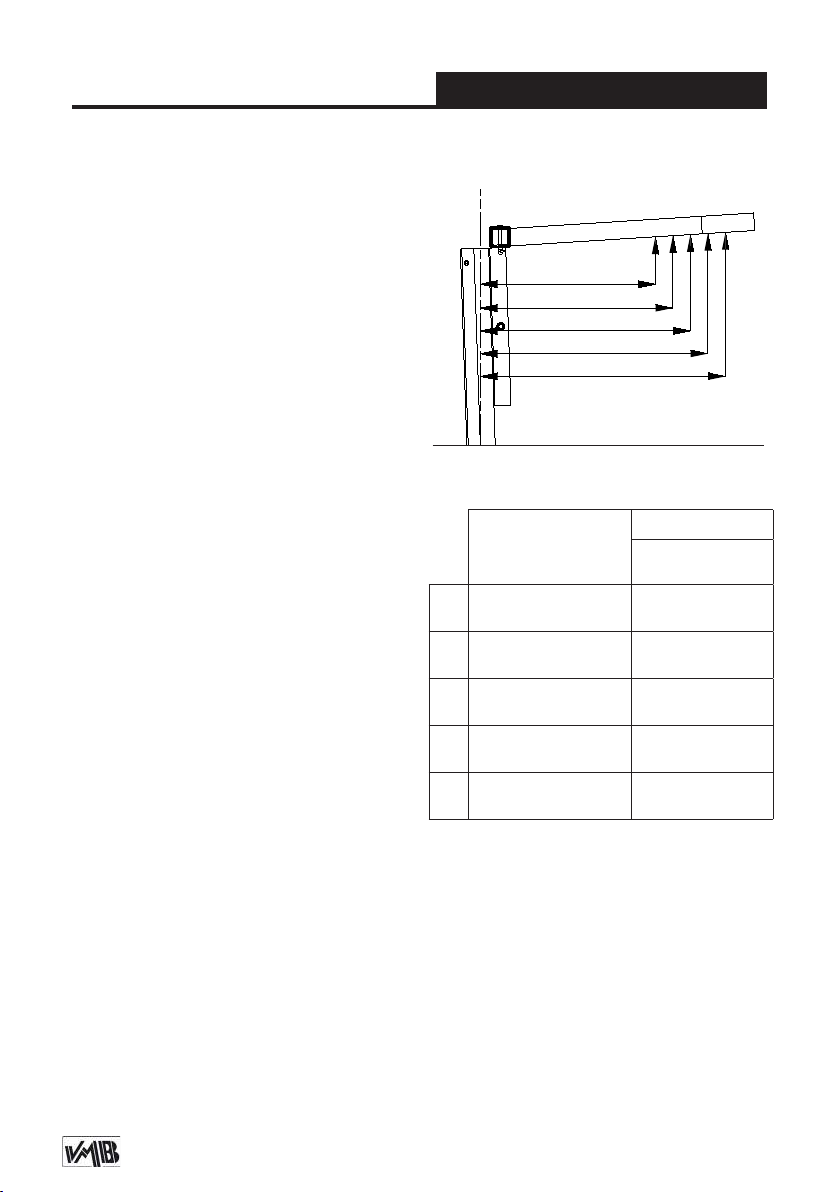
möglich in Richtung des Towers. Die Maxi-
malbelastung reduziert sich, gemäß dem
nebenstehenden Diagramm.
DEUTSCH
Diagram 4.6.1
A
B
C
D
E
Distance from the
load’s center to the
axel of the tower
A
B
C
D
E
50 cm
(1.64’)
55 cm
(1.80’)
60 cm
(1.97’)
65 cm
(2.13’)
70 cm
(2.30’)
Achtung!
Werden zweit Stative dazu benutzt, eine
Traverse oder mehrere Stative dazu be-
nutzt, eine Konstruktion jedweden Typs
anzuheben, ist es fast unmöglich, dass
zwei oder mehrere Bediener in der Lage
sind, die Winde in der exakt gleichen
Maximum load
TL-A300
300 kg
(662 lb)
272 kg
(600 lb)
250 kg
(551 lb)
230 kg
(507 lb)
182 kg
(400 lb)
Depósito legal y copyright. Todos los derechos reservados. 24PRO LIFTS S.L.
Page 25

Bedienungsanleitung
DEUTSCH
Geschwindigkeit zu bedienen, um die Last
anzuheben oder abzusenken.
Ab einem bestimmten Punkt wird sich
jeder Tower in einer anderen Höhe als der
andere benden.
Aus diesem Grund ist es notwendig, dass
die Konstruktion in der Lage ist, diese
Differenz auszuhalten. Bei einer starren
Fixierung und wenn der Höhenunterschied
sehr groß ist, wir die Kraft, die von der
Winde erzeugt wird, die Konstruktion deformieren und dazu führen, dass die Lifte,
ausgelöst durch seitlich wirkende Kräfte,
brechen oder blockieren.
Die Tower können in jeder notwendigen
Zwischenposition belassen werden. Beenden Sie einfach das Drehen der Winde. Die
automatische Bremse wird die Position der
Last halten.
4.7 - Heben:
Die Transportsicherung ( O ) entriegeln.
Den Lift mittels Drehen der Winde ( W )
in Uhrzeigersinn ( N1 ) in die gewünschte
Höhe kurbeln.
4.8 - Halten:
Die Last kann in jeder Position ehalten
werden. Stoppen Sie dazu lediglich das
drehen der Kurbel. Die Automatic in der
Winde und die Fallbremse sichern die
Ladung. Für den Transport des Turmes ist
dieser durch Senken der Einzelabschnitte
herunterzufahren. Es ist sehr wichtig den
Schlitten in seiner Parkposition wieder zu
verriegeln ( B ). Die Ausleger entsperren und
diese in ihre Transportstellung ( S ) bringen.
Die Befestigungsschraube anziehen.
4.9 - Senken:
Zum Transport die Sicherung ( O ) weder
einrasten die Handkurbel der Winde gegen
den Uhrzeigersinn drehen, bis der Lift in
einer Endposition ist. Der Lift kann in jeder
beiliegenden Zwischenstellung angehalten
werden. Durch kurzes anheben der Ladung
mittels der Winde lässt sich ALS - Lock
entriegeln ( rot ). Drücken Sie diese und
lassen Sie die Last mittels Winde ab. Sollte
der ALS – Lock blockieren heben Sie die
Last erneut an und wiederholen Sie den
Vorgang.
5. Wartung.
5.1 - Regelmäßig den Seilzustand kontro-
llieren. Weist ein Seil Drahtbrüche bzw.
Quetschungen auf, ist es sofort durch ein
meues zu ersetzen. Unter keinen Umständen den Hebeturm mit Seilen in schlechtem
Zustand verwenden.
Nur verwindungssteifes Stahlseil nach DIN
3060 verwenden.
5.2 - Der Hebeturm wird werkseitig komplett
geschmiert geliefert. Es wird jedoch
Depósito legal y copyright. Todos los derechos reservados. 25PRO LIFTS S.L.
Page 26
Bedienungsanleitung
DEUTSCH
empfohlen, regelmäßig ( je nach Bedarf )
das Zahnrad des Winde, die Wälzlager der
Antriebswelle und Hülse, das Kurbelgewinde und die Abschnitte zu schmieren.
Achtung: Die Bremsscheiben nicht
einölen oder fetten !!!
5.3 - Der Hebeturm TL-A300 sollte von
einer Fachkraft mindestens einmal jährlich
geprüft werden.
5.4 - Für eine kontinuierliche Betriebs-
sicherheit sind ausschließlich Original
– Ersatzteile zu verwenden. Alle Gewährleistungsansprüche sind für den Anwender
aufgehoben, wenn er Nicht- Original – Ersatzteile verwendet bzw. änderungen am
Produkt selbst vornimmt.
5.5 - Für die Bestellung von Ersatzteilen ist
stets dessen Bestellnummer anzugeben,
welche den Stücklisten-Blättern dieser
Anleitung zu entnehmen ist.
dingten Mängel durch Reparatur order
Austausch.
In Europa gilt eine Garantiezeit von mindestens 24 Monaten.
Von der garantie ausgenommen sind
Schäden aufgrund von unsachgemäBen
Gebrauch, VerschleiB oder Eingriffen
Dritter. Die Garantie umfasst keine Verbrauchsmaterialien und Mängel, die dedn
Wert oder die Gebrauchstaugllichkeit nur
unerheblich beeinträchtigen.
7. Zertikat
BGV-C1
BGG-912
EC Conformity Declaration pursuant to the
EC Machinery Directives 89/392/CE and
98/37/CE: Manual lifters
VMB Service Deutschland:
Tel : 04442 - 92900
Fax: 04442 - 929090
6. Garantie.
Ab Kaufdatum und innerhalb der Garantie-
zeit beim Händler beseitigt die PRO LIFTS
S.L. alle material-order herstellungsbe-
Depósito legal y copyright. Todos los derechos reservados. 26PRO LIFTS S.L.
Page 27
TL-A300
7040L
E.2
D
A.2
A.1
E.3
A.4
A.9
3008
C
3061
3062
3063
3064
3065
B
Depósito legal y copyright. Todos los derechos reservados. 27PRO LIFTS S.L.
Page 28
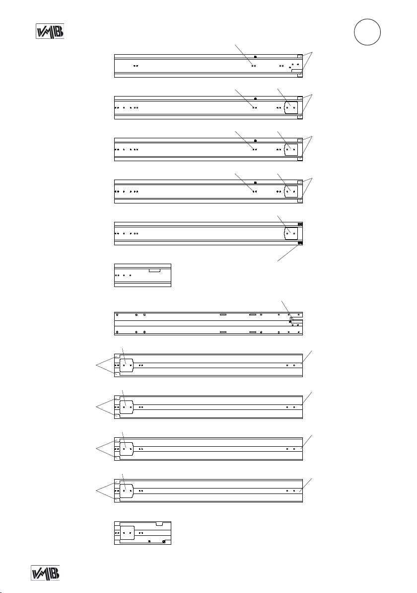
TL-A300
A.8
A
D.2
3061N
D.2
A.7
7566
A.8
A.8
A.8
A.6
A.6
A.6
A.6
A.3
A.5
D.2
3062
D.2
3063
D.2
3064
3065
3061N
A.6.1
3062
D.2
D.2
D.2
A.7
A.7
A.7
A.6.1
3063
A.6.1
3064
A.6.1
3065
7566
Depósito legal y copyright. Todos los derechos reservados. 28PRO LIFTS S.L.
Page 29
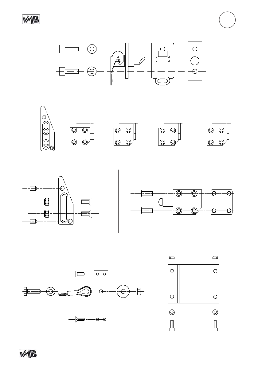
TL-A300
6 mm
3 mm 3 mm
7 mm
7 mm
7 mm
A
A.1
A.2
3253
2244
2244
7208
7208 2152
1540
2152
Profile 4 (TL-A300)
Ref: 3064
Casquillo 12mm Casquillo 10mm Casquillo 10mm Casquillo 10mm
7 mm
3031
1540
Profile 3 (TL-A300)
Ref: 3063
3233
3233
4005 4004
Profile 2 (TL-A300)
Ref: 3062
4 mm
3032
3251
3251
4 mm
3032
Profile 1 (TL-A300)
3031 /
3032
Ref: 3061
4 mm
3032
3252
3253
A.3 A.4
7509
7871
Depósito legal y copyright. Todos los derechos reservados. 29PRO LIFTS S.L.
2140
3250
20472162
3008
3250
7078 7078
3015
2152 2152
2141 2141
Page 30
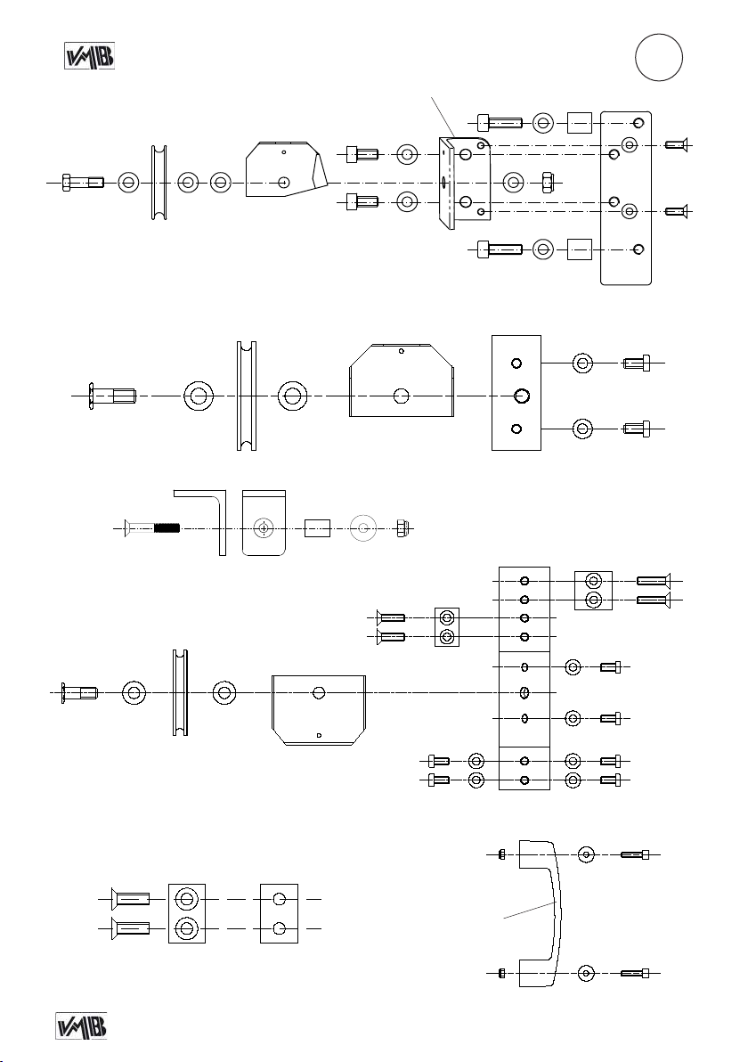
A.5
9200
TL-A300
4056
2047
2047x2
4057
2158
4079
20472158
2047
7962
2047 2140
2047
4078
A
4080
7246
7246
A.6
A.7
A.6.1
7595
4030B
204720477232
7595
7962 2047
7593
204720477232
7550
40844083
7593
7078
7246 (x2)
7234 (x2)
5421
7265
3218
4078
2152
2152
3219
7234
7234
7573 (x2)
A.8
7246
7246
5421
8019
2152 (x2)
A.9
Depósito legal y copyright. Todos los derechos reservados. 30PRO LIFTS S.L.
2244
3000
2244
2152 (x4)
2048
2048
7234 (x4)
7224
7224
Page 31
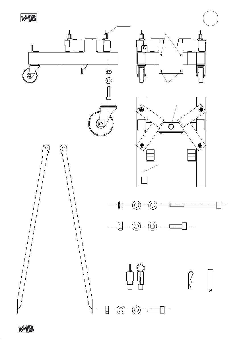
TL-A300
B.5
B
B.2
B.4
B.1
B.2
B.3
2140
2047
7962
7587
B.3
6409
3006
30052047 (x2)2140
79622047 (x2)2140
3070 3070D
B.5
2026
21412152 (x2)7078
Depósito legal y copyright. Todos los derechos reservados. 31PRO LIFTS S.L.
B.6
MR-PAS
PAT-02
Page 32
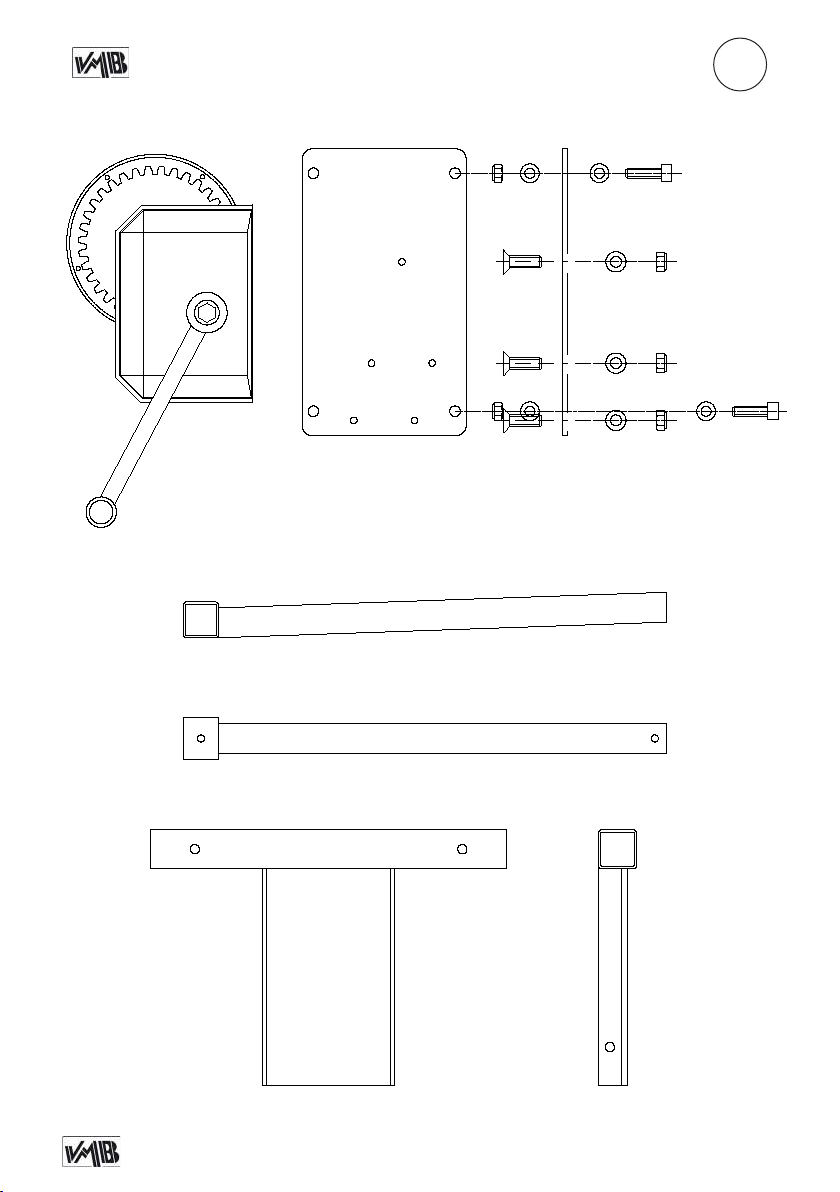
TL-A300
C
7502
3201N
7040L
2044
2044
3257
3257
3257
7061
7061
7061 2044
7061 2044
7061 2044
72407061
7061
7240
3007
Depósito legal y copyright. Todos los derechos reservados. 32PRO LIFTS S.L.
Page 33
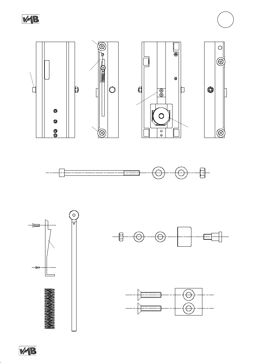
TL-A300
D
D.1
D.3
3250
7247
7566
D.1
7245
D.2
D.3
D.4
D.2
A.7
7872 7242 7242 7243
D.2
7518
7244
C
2044
7061F
72227061
7248
D.4
Depósito legal y copyright. Todos los derechos reservados. 33PRO LIFTS S.L.
7573
7573
3219
Page 34
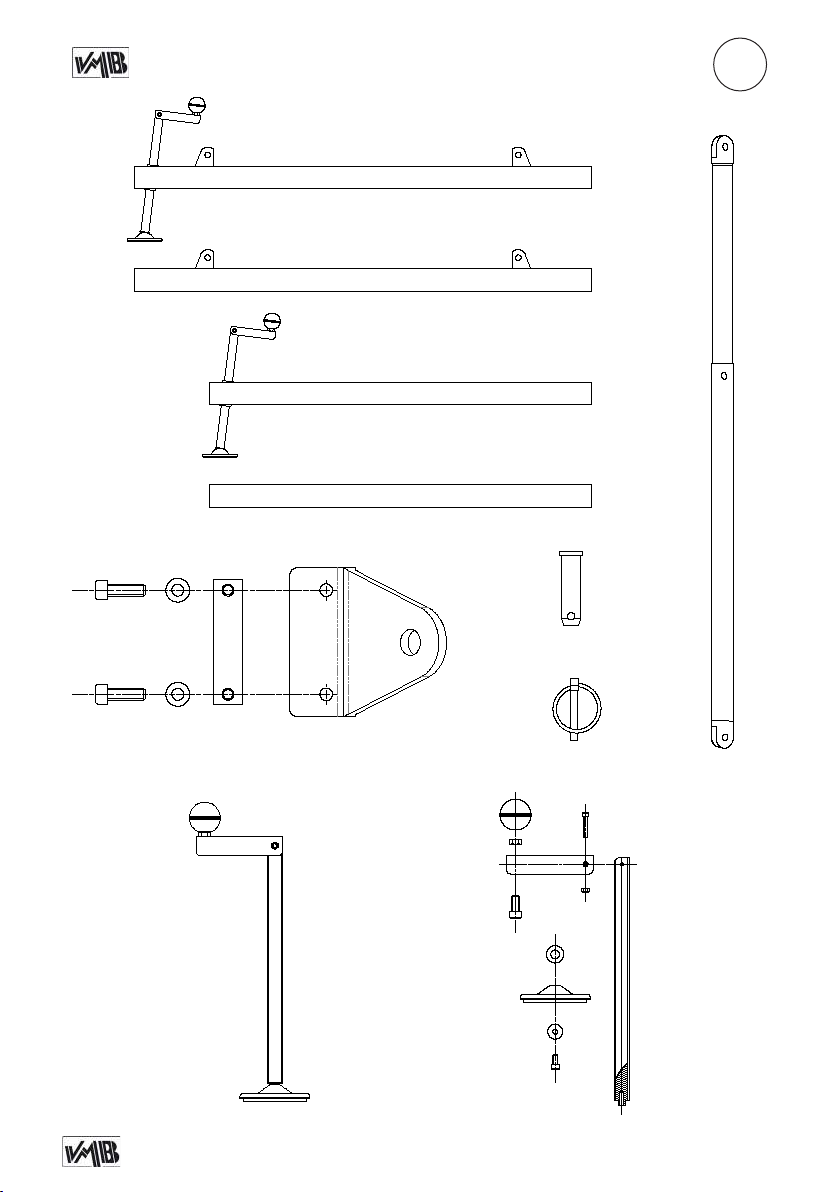
E.1
E.3
2141 2152
TL-A300
E
E.2
3003
3003P
3004
3004P
3020
(x2)
5461
PAS-SPI
E.4
21522141
Stabilizer kit
TL-A300
Ref: 3011N
5466
MR-SPI
7541
7066
7964
3246
7242
7549
7550
3232
Depósito legal y copyright. Todos los derechos reservados. 34PRO LIFTS S.L.
7065
2244
3009N
Page 35
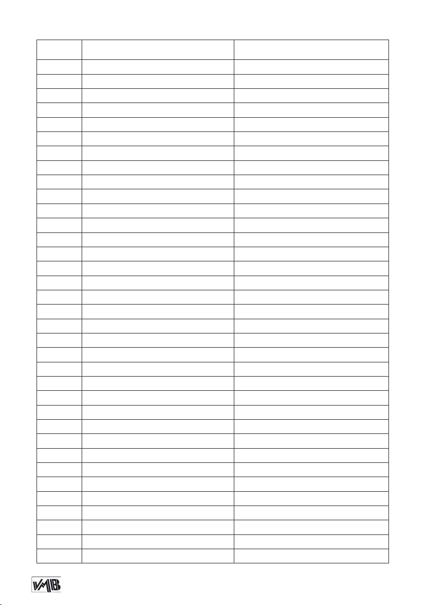
SPARE PARTS LIST / LISTA DE REPUESTOS TL-A300
Code Description GB / USA Descripción ES
1540 (B) SRS Unlock (B Black) Desbloqueador sistema SRS (B Negro)
2026 Safety catch Gatillo de seguridad
2044 M10 Auto-block nut Tuerca autoblocante M10
2047 M12 Washer Arandela M12
2048 M6 Washer Arandela M6
2140 M12 Auto-block nut Tuerca autoblocante M12
2141 M8x25 Allen screw Tornillo allen M8x25
2152 M8 Washer Arandela M8
2158 Allen screw M12x25 Tornillo allen M12x25
2162 M12x45 Hexagonal screw Tornillo hexagonal M12x45
2162N M12x40 Hexagonal Screw Tornillo hexagonal M12x40
2244 M6 Auto-block nut Tuerca autoblocante M6
3000 TL-A300 Plastic transport handle Asa de plástico transporte TL-A300
3003 (B) Complete long leg (B Black) Pata larga completa (B Negro)
3003P (B) Long leg prole (B Black) Perl para larga (B Negro)
3004 (B) Complete short leg (B Black) Pata corta completa (B Negro)
3004P (B) Short leg prole (B Black) Perl para corta (B Negro)
3005 Allen screw M12x100 Tornillo allen M12x100
3006 (B) TL-A300 Base v.07.14 (B Black) Base TL-A300 v.07.14 (B Negro)
3007 (B) Steel fork support (B Black) Soporte brazos de carga acero (B Negro)
3008 Steel cable Ø6 mm x 15.4 m Cable de acero Ø6 mm x 15.4 m
3009N Screw bolt M24x330mm Perno roscado M24x330mm
3011 Complete stabilizer Estabilizador completo
3015 (B) Pulley cover (B Black) Cubrepoleas (B Negro)
3020 (B)
3031 (B) SRS Unit prole 3 (B Black) Pieza retentor SRS tramo 3 (B Negro)
3032 (B) SRS Unit prole 1 & 2 (B Black) Pieza retentor SRS tramo 1 y 2 (B Negro)
3061N (B)
3062 (B) Prole 2 (B Black) TL-A300 (1495mm) Tramo 2 (B Negro) TL-A300 (1495mm)
3063 (B) Prole 3 (B Black) TL-A300 (1495mm) Tramo 3 (B Negro) TL-A300 (1495mm)
3064 (B) Prole 4 (B Black) TL-A300 (1495mm) Tramo 4 (B Negro) TL-A300 (1495mm)
3065 (B) Prole 5 (B Black) TL-A300 (1495mm) Tramo 5 (B Negro) TL-A300 (1495mm)
3070 (B) Left steel strut (B Black) Tirante acero refuerzo trasero (B Negro)
3070D (B) Right steel strut (B Black) Tirante acero refuerzo trasero (B Negro)
3201N (B) Winch xation plate (B Black) Placa portacabrestante (B Negro)
Frontal reinforcement telescopic strut (B Black)
Base prole 1 (B Black) TL-A300 (1495mm) Tramo 1 Base (B Negro) TL-A300 (1495mm)
Tirante refuerzo frontal a patas (B Negro)
Depósito legal y copyright. Todos los derechos reservados. 35PRO LIFTS S.L.
Page 36

Code Description GB / USA Descripción ES
3218 Inferior pulley support alluminium piece Pieza aluminio soporte polea inferior
3219 Wide inner stop piece Tope interior ancho
3232
Allen screw M8x16
3233 Conic screw M6x16 Tornillo cabeza cónica M6x16
3246 M12x25 Allen screw Tornillo allen M12x25
3250 M8x20 Conic screw Tornillo cabeza cónica M8x20
3251 M6x16 Allen screw Tornillo allen M6x16
3252 SRS screwed plate Pletina roscada Retentor
3253 M6x10 Headless allen bolt Tornillo allen sin cabeza M6x10
3257 M10x25 Conic screw Tornillo cabeza cónica M10x25
4004 ALS xation alluminium piece
4005 ALS catch lock Gatillo ALS
4030 (B) Upper stop piece (B Black) Ángulo acero tope plegado (B Negro)
4056 Ø90mm wide pulley Polea ancha Ø90mm
4057 Cable protection Ø90 wide pulley Protector cable Ø90 cubre-polea ancha
4078 Alluminium reinforcement tube Ø25x3mm Tubo refuerzo de aluminio Ø25x3mm
4079 (B) 1st section pulley support steel angle Ángulo acero porta-poleas 1era sección
4080 (B) 1st section support steel piece Pieza acero soporte ángulo porta-poleas
4083 Tornillo M8x50 DIN 7991 Allen screw M8x50 DIN 7991
4084 (B) Casquillo aluminio Ø16x1,5 Long=23mm Aluminium shell Ø16x1,5 Long=23mm
5421 Alluminium stop piece Tope de aluminio
5432 Conic allen screw M8x20 Tornillo allen cabeza cónica M8x20
5461 (B) Fixation piece for strut (B Black)
5466 Screwed piece for strut’s xation Pieza jación oreja de tirante de refuerzo
6409 Spirit level Ø30mm Nivel de burbuja Ø30mm
7040L (B)
Long load support fork (B Black) (74.5cm)
7061 M10 Washer Arandela M10
7061F M10 Thin washer for adjustments Arandela na de ajuste M10
7065 M6x35 Allen screw Tornillo allen M6x35
7066 M12 Nut Tuerca M12
7078 M8 Auto-block nut Tuerca autoblocante M8
7208 M8x35 Allen screw Tornillo allen M8x35
7222 Special screw for nylon roller Tornillo especial para rodillo de nylon
7224 M6x25 Allen screw Tornillo allen M6x25
7232 M12 Special pulley screw Tornillo especial M12 para polea
7234 M8x16 Screw Tornillo M8x16
7240 M10x35 Allen screw Tornillo allen M10x35
Tornillo allen M8x16
Pieza roscada aluminio jación gatillo ALS
Oreja soporte tirante refuerzo frontal (B Negro)
Brazo de carga largo (B Negro) (74.5cm)
Depósito legal y copyright. Todos los derechos reservados. 36PRO LIFTS S.L.
Page 37
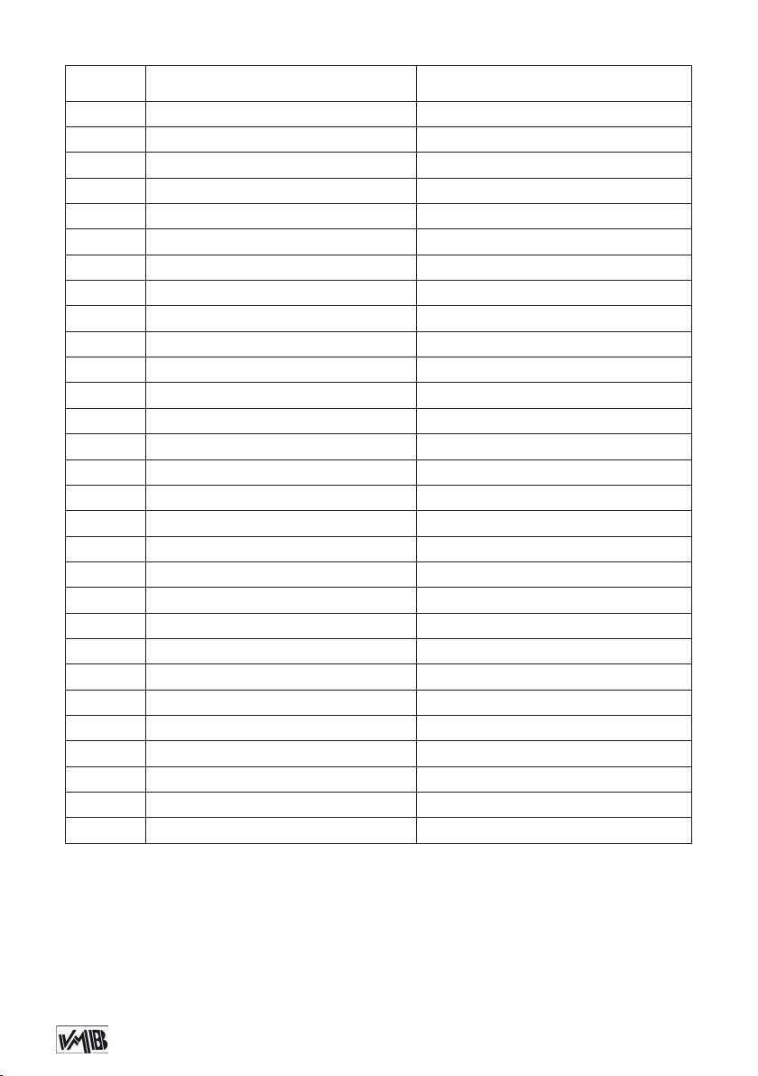
Code Description GB / USA Descripción ES
7242 M14 Washer Arandela M14
7243 M14 Auto-block nut Tuerca autoblocante M14
7244C Inertial brake lock (Ø22mm disk) Varilla freno de inercia (disco Ø22mm)
7245 Brake lock support Soporte varilla freno de inercia
7246 M8x25 Conic screw Tornillo cabeza cónica M8x25
7247 M5x10 Conic screw Tornillo cabeza cónica M5x10
7248 Brake spring Muelle freno de inercia
7265 Pulley support alluminium piece Pieza aluminio soporte polea
7502 900 Kg Reinforced winch Cabrestante 900 Kg Reforzado
7509 (B) Cable xation plate (B Black) Pletina sujección cable (B Negro)
7518 Nylon roller Ø39 Rodillo nylon Ø39
7541 Stabilizer crank ball Ø51 Bola de baquelita Ø51 para estabilizador
7549 Stabilizer round plate Platillo apoyo estabilizador
7550 M8 Washer Arandela carrocero M8
7566 (B) Alluminium lifting carriage (B Black) Carro elevador (B Negro)
7573 M8x30 Conic screw Tornillo cónico M8x30
7587 White wheel Ø98 Rueda blanca Ø98
7593 Cable protection for Ø90 pulley Protección cable para polea Ø90
7595 Steel Ø90 pulley Polea de acero Ø90
7871 M12 Washer Arandela M12
7872 M14x200 Allen screw Tornillo allen M14x200
7962 M12x40 Allen screw Tornill allen M12x40
7964 Steel hand crank for stabilizer Manivela de acero para estabilizador
8019 Threaded alluminium piece inner stop Pletina roscada tope interior de aluminio
9200 M12x45 DIN 912 screw (hardness 12.9) Tornillo M12x45 DIN 912 (Dureza 12.9)
MR-PAS ‘R’ Clip Clip de seguridad ‘R’
MR-SPI Ring safety clip Clip de seguridad anillo
PAS-SPI Fastener steel pin Ø16 x 65.5mm Pasador de acero Ø16 x 65.5mm
PAT-02 Fastener steel pin Ø10 x 88.5mm Pasador de acero Ø10 x 88.5mm
REMEBER TO QUOTE THE TYPE, PRODUCTION YEAR AND
SERIAL NUMBER OF THE TOWERLIFT.
RECUERDE CITAR EL MODELO, EL AÑO DE PRODUCCIÓN Y EL
NÚMERO DE SERIE DE LA TORRE ELEVADORA.
Vergessen Sie nicht den MODELLJAHR DER PRODUKTION und Se-
riennummer des HEBETURM zitieren.
Depósito legal y copyright. Todos los derechos reservados. 37PRO LIFTS S.L.
Page 38
Depósito legal y copyright. Todos los derechos reservados. 38PRO LIFTS S.L.
Page 39

Page 40

facebook / vmblifts
Canal VMBLifts
For further information follow the advise of our technicians:
Para más información consulte con nuestros técnicos en:
PRO LIFTS S.L.
C/ Ciudad de Barcelona Nº19
Pol. Ind. Fuente del Jarro
46988 Paterna (Valencia) Spain
Tlf Export: +34 96 171 81 86
Tlf Nacional: 96 171 81 83
email: [email protected] web: www.prolifts.es
 Loading...