

Page 1
V.05.17
OPERATING INSTRUCTIONS USER MANUAL
MANUAL DE INSTRUCCIONES
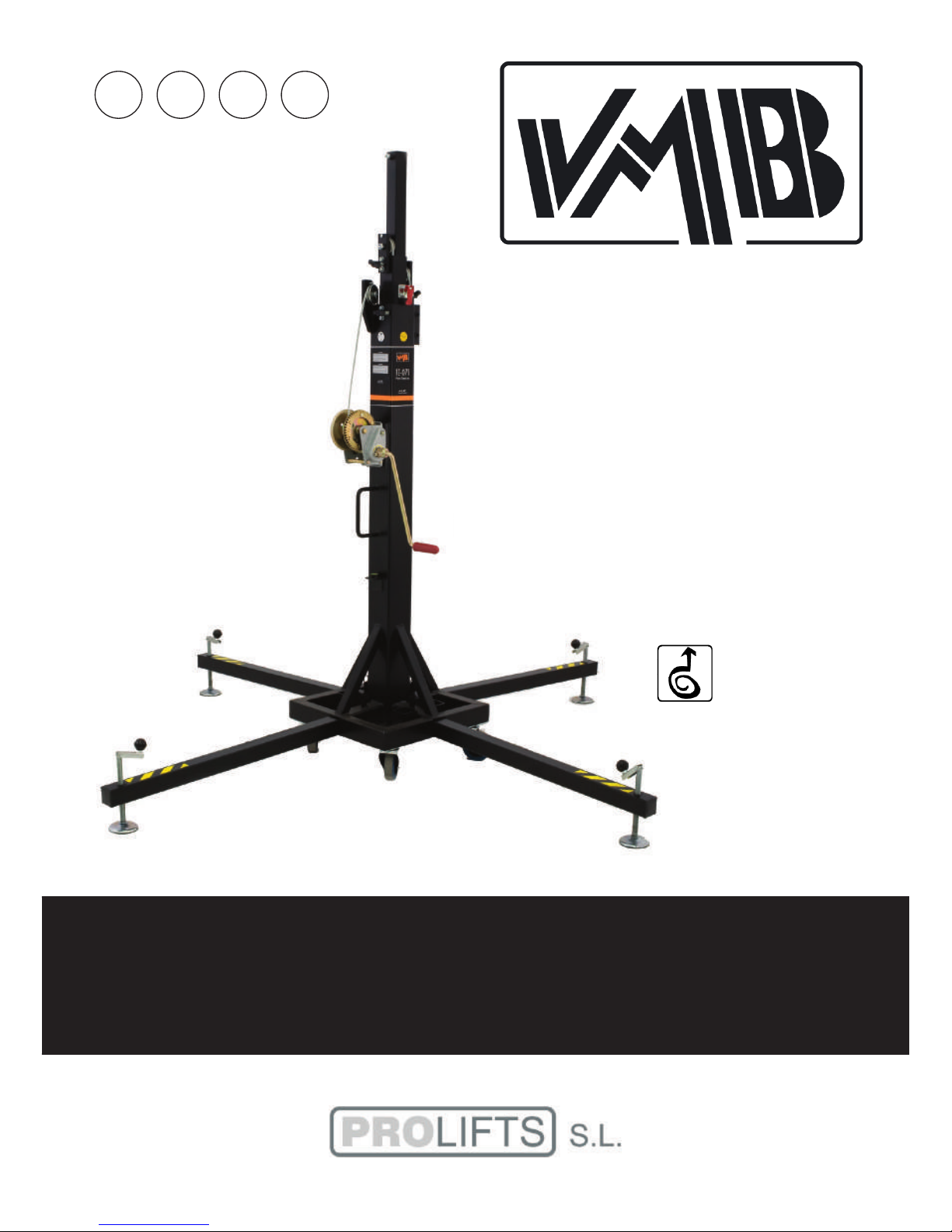
TE-071
TOWERLIFT
TORRE ELEVADORA
GBE
USA
D
TRAVERSENLIFT
Page 2
LIFTING TOWER TE-071
TORRE ELEVADORA TE-071
PRO LIFTS S.L.
C/ Ciudad de Barcelona Nº19
Pol.Ind. Fuente del Jarro
46988 Paterna (Valencia)
Tlf Export: +34 96 171 81 86
Tlf Nacional: 96 171 81 83
info@prolifts.es - www.prolifts.es
Manufacturer - Fabricante
Este manual de usuario y catálogo anexo de piezas de repuesto es propiedad de PRO LIFTS S.L.
Queda prohibida su reproducción total o parcial por cualquier medio que la tecnología actual permita.
Deposito legal y copyright 2016. Todos los derechos reservados.
MADE IN SPAIN (EU)
BGV-C1
BGG-912
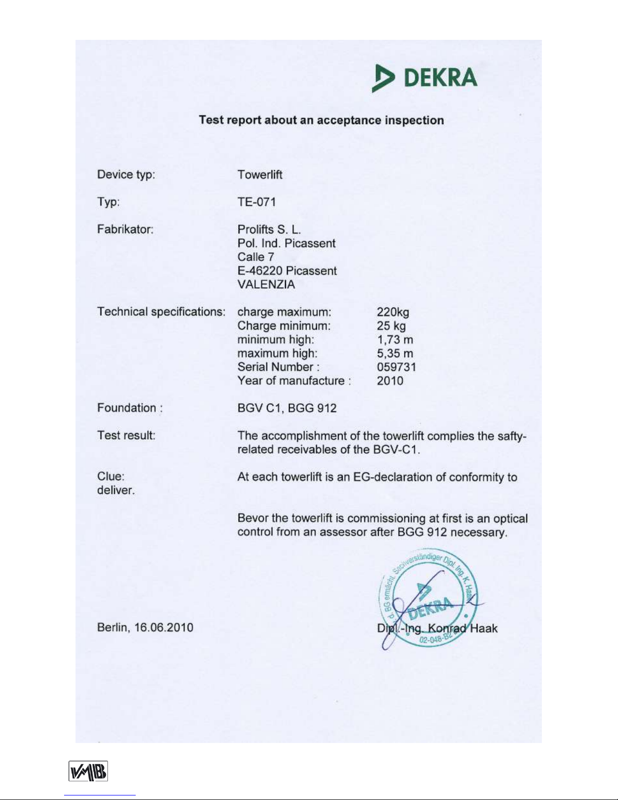
EC Conformity Declaration pursuant to the EC Machinery
Directives 89/392/CE and 98/37/CE: Manual lifters
Find a copy of the certications at the end of this booklet.
Puede ver una copia de las certicaciones al nal del manual.
CERTIFICATIONS / CERTIFICACIONES
Page 3
Depósito legal y copyright 2016. Todos los derechos reservados. 3PRO LIFTS S.L.
TE-071
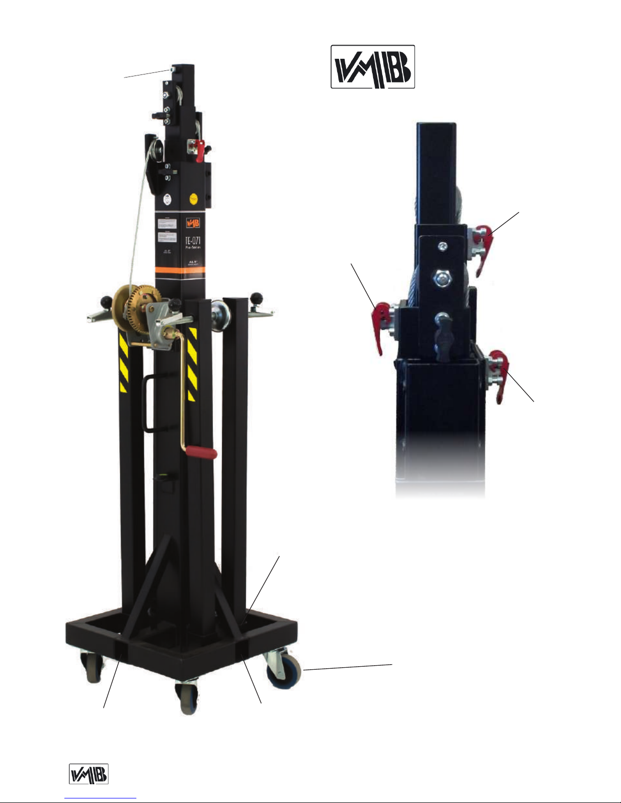
ALS: Security lock / Gatillo seguridad
T: Transport wheels / Ruedas de transporte
S: Transport compartment / Alojamiento de transporte
V: Working compartment / Alojamiento de trabajo
T
V
ALS-1
ALS-2
ALS-3
V
S
A
Page 4
Depósito legal y copyright 2016. Todos los derechos reservados. 4PRO LIFTS S.L.
TE-071
R
H
Q
W
P
N
2
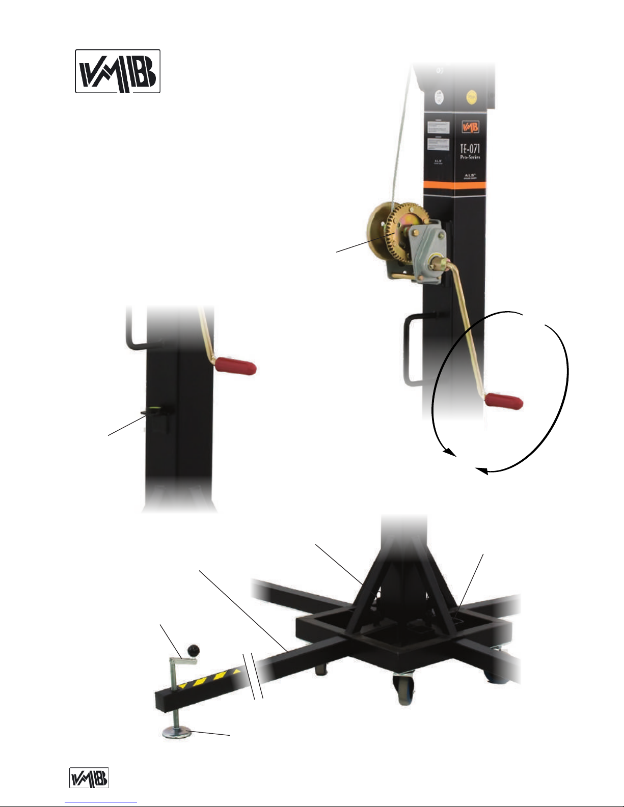
H: Handle / Manivela
N: Force on hand crank / Fuerza sobre manivela
P: Leg / Pata
Q: Stabilizer / Estabilizador
R: Catch pawl / Gatillo bloqueo patas
S: Transport compartment / Alojamiento de transporte
W: Winch / Cabrestante
L
N
1
S
Page 5

Depósito legal y copyright 2016. Todos los derechos reservados. 5PRO LIFTS S.L.
Quick operation guide
ENGLISH
CONTENTS
1. Introduction.
2. Technical information.
3. Safety precautions.
4. Operation.
5. Maintenance.
6. Guarantee.
1. INTRODUCTION
Dear customer,
In order to ensure a safe and reliable operation of the TE-071 towerlift please follow
the instructions in this booklet carefully.
Before operating the lift, read the instructions completely and please note the technical information contained within this
manual.
All VMB products undergo very rigorous
testing, under strict conditions and they
are monitored continuously during the manufacturing process.
In order to guarantee the lifts function and
safety, only original parts from the manufacturer must be used. If any parts other
than those of the manufacturer are used,
or the product is modied in any way, the
user forfeits all warranty rights to claim.
VMB reserves the right to modify the pro-
duct specications without prior notice.
The model type, production year and serial number must be quoted in any queries
or orders for spare parts.
2. TECHNICAL INFORMATION
2.1 - TE-071 Towerlift.
2.2 - Designed to lift loads, such as trus-
sing and lighting, vertically up to different
heights.
2.3 - Maximum load : 220 Kg (485 lb).
2.4 - Minimum load : 25 Kg (55 lb).
2.5 - Maximum height : 5.35 m (17.5’).
2.6 - Folded height : 1.73 m (5.7’).
2.7 - Transport surface: 0.47x0.47x1.73m
(1.54’x1.54’x5.7’).
2.8 - Shipping dimension: 0.49x0.49x1.77m
(1.61’x1.61’x.5.81’).
2.9 - Work surface : 2.1 x 2.1 m
(6.8’ x 6.8’).
2.10 - Unit weight : 71 Kg (157 lb).
2.11 - Adaptator: Ø 35 mm
(PSU-06/PSA-01).
2.12 - Construction material : Steel pro-
les DIN 2394.
2.13 - Four telescopic prole system ope-
rated by steel cable and guided by chan-
nelled steel pulleys with ball bearings.
2.14 - Winch: 450 Kg. maximum load with
automatic brake. Certication CE and
GS TÜV.
2.15 - Cable : Steel DIN 3060. Quality 180
Kg/mm
2
twist resistant.
Cable diameter : Ø6 mm.
Page 6
Depósito legal y copyright 2016. Todos los derechos reservados. 6PRO LIFTS S.L.
Quick operation guide
ENGLISH
3. SAFETY PRECAUTIONS.
2.16 - Exclusive ALS system (Auto-Lock
Security), pat. pen. 200501056.hed in satin polyester.
2.17 - Adjustable stabilizing feet with ruber
non-slip supports.
2.18 - Safety catches to anchor the legs.
2.19 - Antirust protection, primed paint
with cured polyester dust cover. The tower
can be supplied with natural aluminium
nish or black (version B).
2.20 - Spirit level to adjust the tower vertically.
2.21 - Swivel wheels to transport the lift
when folded.
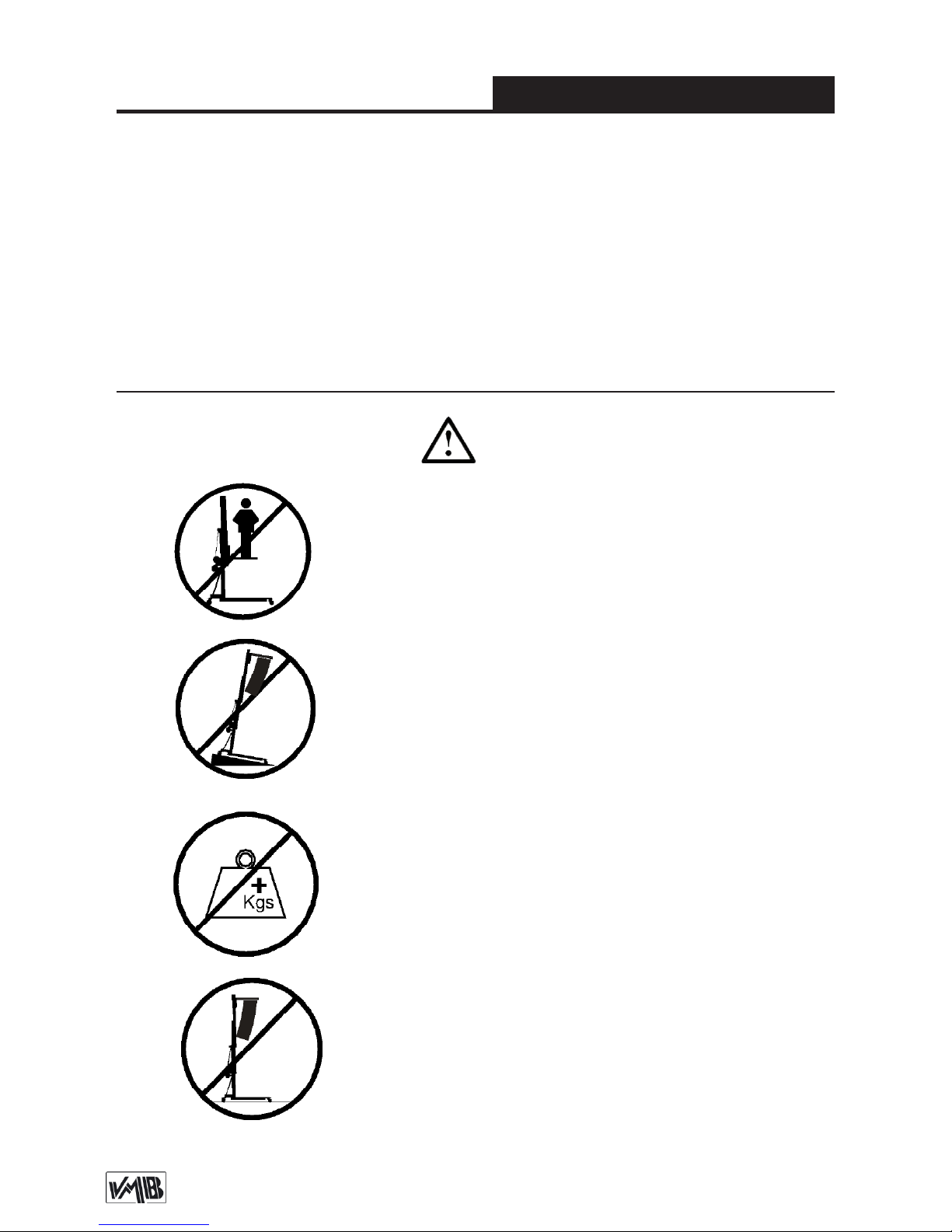
3.1 - The TE-071 is a machine designed to elevate
loads upwards in a vertical direction, It should NEVER
be used as a platform to elevate people.
3.3 - The maximum load indicated on the characteristics
label and the instructions manual should not be exceeded.
3.4 - This lift should NEVER be used to elevate a load
that has not been properly checked. It is necessary to
verify that the load is correctly supported and centred
on the appropriate lift support so that the weight of the
load will only elevate in a vertical direction.
3.2 - Only place the lift on hard, at surfaces always
checking that it is in a vertical position by using the bub-
ble level indicator (L) found on the base section. Adjust
the leg stabilizers (Q) by turning the handles (H) to level
if necessary. NEVER use wedges or other foreign objects to balance the lift.
Page 7
Depósito legal y copyright 2016. Todos los derechos reservados. 7PRO LIFTS S.L.
Quick operation guide
ENGLISH
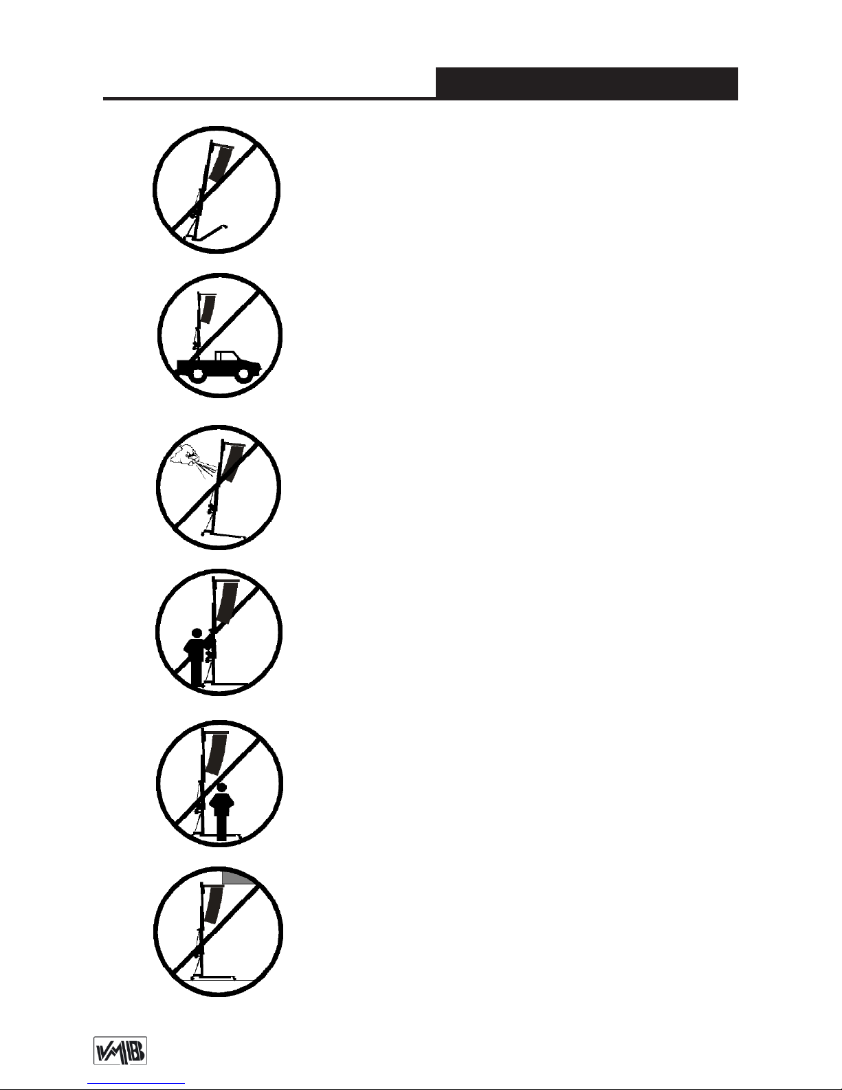
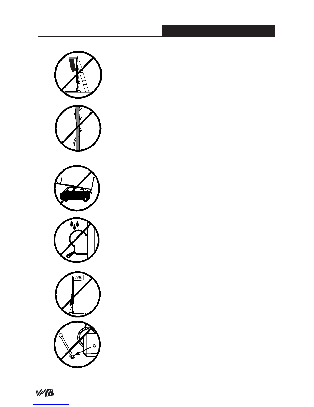
3.6 - NEVER use the lift on a vehicle or any other mobile
surface.
3.7 - If there is a possibility of strong winds or gusts,
place the lift on the ground rmly and secure it with the
use of straps. NEVER attach a strap to a vehicle or any
other object that can possibly be moved.
3.8 - NEVER move the lift whilst it is carrying a load. It
is not advisable to carry out any type of horizontal movement even small positional adjustments.
3.9 - NEVER allow any team member below the load or
anybody else in the lifts operating zone.
3.10 - Take care with all obstacles above the lift and
its extension zone such as cornices, balconies, and
luminous signboards. It is very important to avoid the
presence of all types of cables below the extended lift.
3.5 - Check that the legs (P) are placed and set-up correctly with their safety pins (R) inserted and locked.
Page 8
Depósito legal y copyright 2016. Todos los derechos reservados. 8PRO LIFTS S.L.
Quick operation guide
ENGLISH
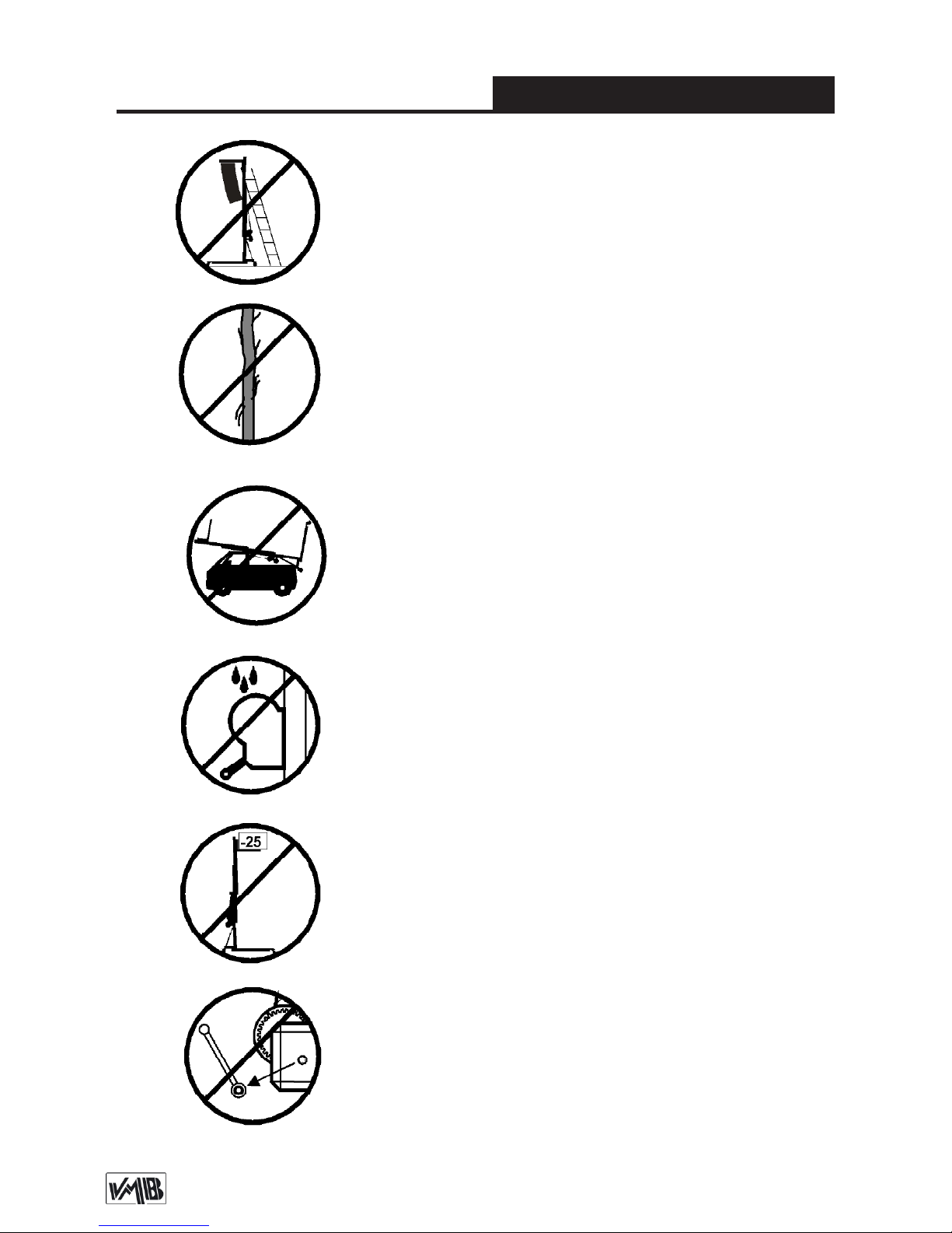
3.11 - Do not use stepladders on the lift or use it as a
support for them.
3.12 - Before using the lift, check the condition of the
cable. The cable should not have broken threads or
show any signs of crushed/attened areas. NEVER use
faulty cables, always change them if there is any doubt.
Only use VMB steel cables; reference: DIN 3060.
Quality: 180KG/mm and torsion resistant.
3.14 - Do not grease or lubricate the winch’s braking
mechanism. The brake disks have been greased with
a special heat and pressure resistant solution. Other
products should not be used to avoid negative effects
regarding the braking mechanism.
3.15 - The minimum load to avoid problems regarding
the braking mechanism is 25Kg. Without this load the
brake will not work.
3.16 - NEVER take apart the crank of the winch when
the lift is carrying a load or extended.
3.13 - All sections must be lowered rst, and the legs
placed in its transport position, before transportation.
Page 9
Depósito legal y copyright 2016. Todos los derechos reservados. 9PRO LIFTS S.L.
Quick operation guide
ENGLISH
4. USER INSTRUCTIONS.
4.1 - Place the lift on its working position,
in a rm, at surface with the help of the
swivel wheels (T).
4.2 - Remove the legs from their trans-
port supports (S) and fully insert them into
their working positions (V) checking that
they are xed by the catches (R). Check
that the lift is in vertical position using the
spirit level (L) at the base prole, adjust
the stabilizer (Q), turning the handle (H)
if necesary.
4.3 - THE MAXIMUM LOAD IS 220 Kg
(485 lb). The lift should NEVER be over-
loaded (over 220 Kg). Safety at work is
the most important issue. Untighten the
screw (A) and place the load onto the lift
using an adequate support according to
the need, use so that the weight of the
load will only be elevated in a vertical direction. The minimum load is 25 Kg.
4.4 - Elevation: Turn the winch crank
clockwise (N
1
) to lift the tower, the red
ALS lock enable the lift to rise and automatically block the proles whilst rising,
ensuring that the load will never fall.
4.5 - Blocking: Once the system is eleva-
ted to its required height, gently turn the
handle in an anti-clockwise (N
2
) direction
to introduce the ALS locks in its corresponding hole and block the proles. The
ALS lock will take the pressure of the load
and release strain applied on the cable.
Security system ALS
The TE-71 incorporates the patented
security system ALS (Automatic Lock
Security). This VMB red trigger system
automatically blocks the tower in the position it is left in. Each section of lift has an
ALS that blocks the section in the unlikely
event of the cable breaking.
4.6 - Lowering: To bring the lift down you
need to rst turn the winch handle slightly
clockwise (N
1
) and at the same time pull
the red ALS-1 lock out. This releases the
blocking systems. Then turn the handle
anti-clockwise (N
2
), whilst maintaining
the ALS-1 lock pulled out until the prole
has been completely lowered. All red ALS
locks should be pulled out one by one
whilst the handle is turned anti-clockwise
and the proles are brought down, one by
one.
CAUTION
When two towers are used to elevate a
bridge, down truss or many towers to elevate a structure of any type, it is almost
3.17 - Only original replacement parts should be used.
ORIGINAL
Page 10
Depósito legal y copyright 2016. Todos los derechos reservados. 10PRO LIFTS S.L.
Quick operation guide
ENGLISH
to use, the gearing, the axis bearings, the
spiral of the crank, and the sections.
5.3 - All lifts should undergo an annual
technical inspection carried out by an
authorized VMB dealer to check the certications and general condition of all the
lift’s elements and security systems involved in the lift’s use.
5.4 - Only use original spare parts to guarantee a continued security level. The
user loses all rights to warranty if any spare parts other than originals are used or
carries out any modication or alteration
to the towerlift.
5.5 - To request a spare part please indicate the corresponding code which can
be found in this manual together with the
lift’s serial number and year of manufacture.
6. GUARANTEE.
The warranty period for this lift is 2 years
from the date of purchase.
PRO LIFTS S.L. promises, that from the
date of purchase and during the warranty
period to resolve any faults that may occur, produced through defect material or
fabrication. Damage caused by improper
use, product modication, third party manipulation or accidental re are not cove-
red by this warranty.
impossible that two or more people co-ordinate the winches elevating or lowering
the loads, at exactly the same pace. At a
certain point each tower will be extended
to a height different to that of the others.
For this reason it is necessary that the
structure does not stretch and allows
for these differences. With a rigid xa-
tion and if the level difference is signicant, the force generated from the handle
of the winch will deform the structure and
apply a lateral force to the lifts causing
them to break and block.
4.7 - Transport:
For the transport of the tower is necessary
to fold the machine lowering every prole
completely. Once the towerlift is completely folded, place the legs in their transport compartment (S) and the lift is ready
to be transported.
5. MAINTENANCE.
5.1 - Regularly check the state of the ca-
ble. If the cable has broken threads, or if
it shows any signs of crushed/attened
areas, it should be changed and replaced
immediately with a new one. Do not use
the lift if the cables are in bad condition.
Only use VMB steel cables reference: DIN
3060 torsion resistant.
5.2 - The lift is supplied from the factory
completely greased. However, it is recommended to periodically grease according
Page 11

Depósito legal y copyright 2016. Todos los derechos reservados. 11PRO LIFTS S.L.
Manual de usuario
ESPAÑOL
CONTENIDO
1. Introducción.
2. Información técnica.
3. Precauciones de seguridad.
4. Instrucciones de uso.
5. Mantenimiento.
6. Garantía.
1. INTRODUCCIÓN
Estimado cliente: Con el n de garantizar un funcionamiento seguro y able de
la torre elevadora TE-071 por favor, siga
cuidadosamente las instrucciones de este
manual.
Antes de manipular la torre elevadora,
lea las instrucciones completas y tenga
en cuenta la información técnica contenida en este manual. Todos los productos de VMB se someten a pruebas muy
rigurosas, en condiciones estrictas y son
monitorizados continuamente durante el
proceso de fabricación. Con el n de garantizar el correcto funcionamiento y seguridad de los elevadores, sólo deben ser
utilizadas piezas originales del fabricante.
Si se utilizan piezas que no sean las originales del fabricante, o el producto se mo-
dica de alguna manera, el usuario pierde
todos los derechos de garantía.
VMB se reserva el derecho de modicar
las especicaciones y las piezas del pro-
ducto sin previo aviso. El tipo de modelo,
año de producción y el número de serie
deben ser citadas en cualquier consulta o
pedido de piezas de recambio.
2. INFORMACIÓN TÉCNICA
2.1 - Torre elevadora TE-071.
2.2 - Diseñada para levantar sistemas de
trusses e iluminación en sentido vertical a
diferentes alturas.
2.3 - Carga máxima: 220 kg (485 lb).
2.4 - Carga mínima: 25 Kg (55 lb).
2,5 - Altura máxima: 5.35 m (17.5’).
2.6 - Altura plegada: 1,73 m (5.7’).
2.7 - Dimensiones torre plegada:
0.47x0.47x1.73m (1.54’x1.54’x5.7’).
2.8 - Dimensiones de caja transporte:
0.49x0.49x1.77m (1.61’x1.61’x.5.81’).
2.9 - Área de la base: 2.1 x 2.1 m
(6.8’ x 6.8’).
2.10 - Peso de la torre: 71 kg (157 lb).
2.11 - Adaptador: Ø 35 mm
(PSU-06/PSA-01).
2.12 - Material de construcción: Perles
de acero DIN 2394
2.13 - Sistema de cuatro perles telescó-
picos accionados con cabestrante por cable de acero y guiado por poleas de acero
acanaladas con cojinetes de bolas.
2.14 - Cabestrante: 450 kg de carga máxi-
ma con freno automático de retención de
la carga. Certicación CE y GS TÜV.
2.15 - Cable: Acero DIN 3060. Calidad de
resistencia a la torsión 180 kg/mm
2
.
Diámetro del cable: Ø6 mm.
2.16 - Sistema exclusivo ALS (Auto-bloqueo de seguridad), pat. pen. 200501056.
hed acabado en poliester satinado.
Page 12

Depósito legal y copyright 2016. Todos los derechos reservados. 12PRO LIFTS S.L.
Manual de usuario
ESPAÑOL
3. PRECAUCIONES DE SEGURIDAD
3.4 - Este elevador NUNCA debe utilizarse para ele-
var una carga que no ha sido correctamente revisada.
Es necesario vericar que la carga está correctamente
apoyada y centrada en el soporte de elevación apropiado para que el peso de la carga sólo actúe en una
dirección vertical.
2.17 - Patas estabilizadoras ajustables
con soportes de goma antideslizante.
2.18 - Gatillos de seguirdad para anclar
las patas.
2.19 - Protección anti-óxido, imprimación
con pintura de polvo poliester al horno. La
torre puede ser suministrada con acabado natural de aluminio o negro (versión
B).
2.20 - Nivel de burbuja para ajustar la verticalidad de la torre.
2.21 - Ruedas direccionales para el transporte de la torre cuando este plegada.
3.1 - La torre elevadora TE-071 es una máquna diseñada para la elevación de cargas en dirección vertical.
NUNCA se debe utilizar como plataforma eleavadora
de personas.
3.3 - La carga máxima indicada en las características
técnicas mostradas en la etiqueta de la torre o en este
manual NO deben ser excedidas.
3.2 - Colocar el elevador sólo en supercies rmes y
planas, vericando que está en posición vertical, utili-
zando el indicador de nivel de burbuja (L) que se encuentra en la base. Ajuste los estabilizadores (Q) girando las manivelas (H) hasta nivelar, si es necesario.
Nunca utilice cuñas u otros objetos extraños para equilibrar el elevador.
Page 13

Depósito legal y copyright 2016. Todos los derechos reservados. 13PRO LIFTS S.L.
Manual de usuario
ESPAÑOL
3.6 - NUNCA use el elevador sobre un vehículo o cualquier
supercie móvil.
3.7 - Si existe la posibilidad de vientos fuertes o ráfagas,
coloque el elevador en el suelo con rmeza y jelo mediante
tirantes tensores. Nunca je un tirante a un vehículo o cual-
quier otro objeto que se pueda mover.
3.8 - NUNCA mueva el elevador mientras esté cargado. No
es aconsejable llevar a cabo cualquier tipo de movimiento
horizontal, ni tan sólo pequeños ajustes de posición.
3.9 - NUNCA permita que ningún miembro del equipo o
cualquier otra persona se sitúe debajo de la carga en la
zona de operación de las torres elevadoras.
3.10 - Tenga cuidado con todos los obstáculos por encima
de la elevación y su zona de extensión, como cornisas, balcones, letreros luminosos, etc. Es muy importante evitar la
presencia de todo tipo de cables por debajo de la torre extendida.
3.5 - Comprobar que las patas (P) estén situadas correctamente, y jadas con los gatillos de seguridad (R) los cuales
deben estar introducidos y bloqueados.
Page 14
Depósito legal y copyright 2016. Todos los derechos reservados. 14PRO LIFTS S.L.
Manual de usuario
ESPAÑOL
3.12 - Antes de utilizar el elevador, compruebe el estado
del cable. El cable no debe contener hilos rotos o mostrar
signos de áreas aplastadas/aplanadas.
NUNCA use cables defectuosos, siempre debe cambiarlos
si hay alguna duda. Utilice solamente cable de acero VMB
referencia: DIN 3060. Calidad: 180kg/mm y resistente a la
torsión.
3.13 - Antes de transportar la torre, todos los tramos deben
ser bajados, y las patas deben extraerse y colocarse en su
posición de transporte.
3.14 - No engrasar ni lubricar el mecanismo de freno del
cabestrante. Los discos de freno vienen engrasados con
una solución especial resistente a la presión y al calor. No
deben utilizarse otros productos, para evitar los efectos
negativos sobre el mecanismo de frenado.
3.15 - La carga mínima para evitar problemas relaciona-
dos con el mecanismo de rotura es 25 kg. Sin esta carga
mínima el freno no funcionará.
3.16 - NUNCA desmontar la manivela del cabrestante
cuando el elevador está soportando una carga o extendido.
3.11 - No usar escaleras encima del elevador ni utilizarlo
como un apoyo para éstas.
Page 15

Depósito legal y copyright 2016. Todos los derechos reservados. 15PRO LIFTS S.L.
Manual de usuario
ESPAÑOL
4. INSTRUCCIONES DE USO.
4.1 - Colocar el elevador sobre una super-
cie rme y plana de la zona de trabajo
sirviendose de las ruedas direccionales
de transporte (T).
4.2 - Extraiga las patas (P) de su alojamiento para transporte (S) e insertelas
totalmente en su posición de trabajo (V),
comprobando que los gatillos de seguridad (R) se insertan y jan la pata. Com-
pruebe que la torre esta en posición vertical sirviendose del nivel de burbuja (L)
situado en el perl base, si es necesario
ajuste la vertical de la torre con los estabilizadores (Q) de las patas girando las
manivelas (H).
4.3 - LA CARGA MÁXIMA ES 220 kg
(485 lb). El elevador NUNCA debe ser so-
brecargado (más de 220 kg). La Seguridad en el Trabajo es el elemento más importante. Aoje el tornillo de sujeción (A) y
coloque la carga en el elevador mediante
un soporte adecuado según la necesidad,
de modo que el peso de la carga sólo actúe en dirección vertical.
La carga mínima son 25 kg.
4.4 - Elevación: Gire la manivela del
cabestrante en sentido horario (N
1
) para
elevar la torre. Los gatillos ALS rojos permiten a la torre elevarse y bloquear automáticamente los tramos mientras esta
subiendo, asegurando que la carga nunca caerá.
4.5 - Bloqueo: Una vez el sistema esta
elevado hasta la altura deseada, gire despacio la manivela en sentido anti-horario
(N
2
) para introducir los gatillos ALS en su
posición correspondiente y así asegurar
el bloqueo de los perles. El gatillo ALS
tomará la presión de la carga y liberará
tensión en el cable.
Sistema de seguridad ALS
La TE-071 incorpora el sistema de seguridad patentado ALS (bloqueo automático
3.17 - Sólo deben ser utilizadas piezas de repuesto
originales de VMB PRO LIFTS S.L.
ORIGINAL
Page 16

Depósito legal y copyright 2016. Todos los derechos reservados. 16PRO LIFTS S.L.
Manual de usuario
ESPAÑOL
Por ello, es necesario que la estructura
no se estire y permita estas diferencias. Con una jación rígida y si la dife-
rencia de nivel es importante, la fuerza
generada a partir de la manivela del cabrestante deformará la estructura y aplicará una fuerza lateral a los elevadores
provocando su bloqueo y ruptura.
4.7 - Transporte:
Para el transporte de la torre es necesario plegar la máquina bajando todos los
tramos completamente. Una vez la torre
haya sido plegada, coloque las patas en
su alojamiento para transporte (S) y la torre ya estará lista para su transporte.
5. MANTENIMIENTO
5.1 - Comprobar periódicamente el esta-
do del cable. Si en el cable existen hilos
rotos, o si muestra signos de zonas aplastadas/aplanadas, debe ser sustituido inmediatamente por uno nuevo. No use el
elevador si los cables están en mal estado. Utilice solamente cable de acero DIN
3060 resistente a la torsión.
5.2 - La torre elevadora es suministrada
de fábrica completamente engrasada.
Sin embargo, se recomienda un engrase
periódico, según el uso, de las ruedas de
fricción, los cojinetes de eje, la espiral de
la manivela, y los tramos.
de seguridad). Este sistema VMB de gatillo rojo bloquea automáticamente la torre
en la posición que se deja. Cada tramo
de elevación tiene un ALS que bloquea
el tramo en el caso improbable de que el
cable se rompa.
4.6 - Descenso: Para descender la torre
es necesario, primero girar la manivela
del cabrestante ligeramente en sentido
horario (N
1
) y al mismo tiempo tirar del
ALS-1 rojo para desbloquear, esto libera
el sistema de bloqueo. A continuación,
gire la manivela en sentido anti-horario
(N
2
), mientras desciende el tramo tirar
del ALS-1 para desbloquear hasta que el
tramo haya sido completamente bajado.
Todos los gatillos rojos ALS deben ser
desbloqueados uno a uno mientras giramos la manivela en sentido anti-horario
(N
2
) para así descender los perles, uno
a uno.
PRECAUCIÓN
Cuando se utilizan dos torres para elevar un puente, descender truss o varias
torres para elevar una estructura de cualquier tipo, es casi imposible que dos o
más personas coordinen los cabrestantes exactamente a la misma velocidad al
elevar o bajar las cargas. En un momento
determinado cada torre se elevará a una
altura diferente a la de las demás.
Page 17

Depósito legal y copyright 2016. Todos los derechos reservados. 17PRO LIFTS S.L.
Manual de usuario
ESPAÑOL
6. GARANTÍA
El período de garantía para este elevador
es de 2 años a partir de la fecha de compra.
PRO LIFTS S.L. se compromete, que a
partir de la fecha de compra y durante el
período de garantía, a resolver los fallos
que puedan producirse, debidos a material defectuoso o fabricación. Los daños
causados por un uso inadecuado, modi-
cación del producto, la manipulación de
terceros o incendio accidental no están
cubiertos por esta garantía.
RECUERDE: NUNCA engrasar ni lubricar
el mecanismo de freno. No es necesario
engrasar los discos de freno.
Los discos de freno vienen engrasados
con una solución especial resistente a
la presión y al calor. No deben utilizarse
otros productos, para evitar los efectos
negativos sobre el mecanismo de frenado.
5.3 - Todos los elevadores deben someterse a una inspección técnica anual llevada a cabo por un distribuidor autorizado
VMB para comprobar las certicaciones y
el estado general de todos los elementos
de elevación y sistemas de seguridad que
intervienen en el uso del elevador.
5.4 - Utilice únicamente piezas de repuesto originales para garantizar el nivel de
seguridad de forma continuada. El usuario pierde todos los derechos de garantía
si las piezas de repuesto utilizadas no son
originales o se utilizan o se lleva a cabo
cualquier modicación o alteración de la
torre elevadora.
5.5 - Para solicitar una pieza de recambio indique el código correspondiente que
se encuentra en este manual junto con el
número de serie de la torre y el año de
fabricación.
Page 18

Depósito legal y copyright 2016. Todos los derechos reservados. 18PRO LIFTS S.L.
Bedienungsanleitung
DEUTSCH
INHALTSVERZEICHNIS
1. Einführung.
2. Technische Daten.
3. Sicherheitsmaßnahmen.
4. Bedienungsanleitung.
5. Wartung.
6. Zertikat
1. EINFÜHRUNG
Sehr geehrter Kunde,
die vorliegende Betriebsanleitung wurde
mit dem Zweck erstellt, eine zuverlässige
Bedienung des TE-071 Hebeturms zu
ermöglichen. Lesen Sie bitte die Betriebsanleitung vor Inbetriebnahme Heberturms
sorgfältig durch.
Bitte beachten Sie auch die technische
Daten.
Unsere Produkte unterliegen strengsten
Prüfungen und Kontrollen bei der Fertigung.
Es sind ausschließlich Original-Ersatzteile
zu verwenden. Für den Anwender werden
alle Gewährleistungsansprüche aufgehoben, wenn er Nicht-Original-Ersatzeile
verwendet bzw. änderungen am Produkt
selbst vormimmt.
2. TECHNISCHE DATEN
2.1 - Hebeturm, Typ TE-071.
2.2 - Das Gerät ist zum senkrechten Heben
von Lasten, wie auf verschiede Höhen,
konzipiert worden.
2.3 - Zulässige Hubkraft : 220 Kg.
2.4 - Mindesthublast : 25 Kg.
2.5 - Zulässige Hubhöhe : 5.35 m.
2.6 - Mindeshubhöhe : 1,73 m.
2.7 - Gefaltete Dimensionen:
0.47x0.47x1.73m.
2.8 - Abmessungen Box:
0.49x0.49x1.77m
2.9 - Grundplattenäche : 2.1 x 2.1 m.
2.10 - Transportgewicht : 71 Kg.
2.11 - Werkstoff : Stahlprol nach DIN 2394.
2.12 - Teleskopierbares System, bestehend
aus swe, von einem über genufete Rollen
mit Wälzlagern geführten Stahlseil angetriebenen Abschnitten.
2.13 - Die Winde, mit einer zulässigen Hu-
blast von 450 Kg. is mit einer automatischen
Lasthaltebremse ausgestattet.
CE und GS TÜV.
2.14 - Seil : aus Stahl nach DIN 3060.
Gute180 Kg/mm
2
verwindungsstelf.
2.15 - Seildurchmesser : Ø6 mm.
Page 19

Depósito legal y copyright 2016. Todos los derechos reservados. 19PRO LIFTS S.L.
Bedienungsanleitung
DEUTSCH
2.16 - Arretierung der Turmabschnitte auf
die Arbeitshöhe über Sicherheitsbolzen aus
Stall, Werkstoff : ST-37.
2.17 - Ausleger mit rutschfesten Gummi-
füßen aus synthetischem Kautschuk.
2.18 - Verankerung der Ausleger über
Sicherheitsklinken.
2.19 - Wasserwaage zum Einstellen der
senkrechten Turmlage.
2.20 - Korrosionsschutz und Veredelung
durch elektrolytische Verzinkung.
3. SICHERHEITSMAßNAHMEN.
3.1 - Den Hubturm nur auf harten und
ebenen Flächen aufstellen.
3.2 - Achten Sie bitte darauf, daß die Ausle-
ger vollkommen eingeschoben und mittels
der Sicherheitsbolzen befestigt sind (R).
3.3 - Prüfen Sie bitte, ob der Lift senkrecht
steht.
3.4 - Prüfen Sie bitte, ob der turm in seiner
Arbeitsstellung mittels Sicherheitsbolzen
(M1, M2) xiert ist.
3.5 - Bei Freiluftanwendungen, den Turm auf
festen Boden stellen und mittels Seilanker
gegen die Windbelastung schützen.
3.6 - Keine Leiter auf dem Turm verwenden
bzw. auf diesem anlehen.
3.7 - Achten Sie bitte auf herausragende
Teile (wie Seile Drähte, Deckenvorsprünge
usw.) oberhalb des Turmes.
3.8 - Niemand soll sich unter dem Turm
aufhalten.
3.9 - Den Turm nicht bewegen, wenn dieser
unter Last und ausgefahren ist.
3.10 - Vor der Verwendung des Turms den
Seilzustand kontrollieren. Das Seil darf
keine drahtbrüche bzw. Quetschstellen
aufweisen. Unter keinen Umständen Seile
in schlechtem Zustand verwenden.
3.11 - Niemals die Windelkurbel (W) bei
unter Last stehendem und ausgefahrenen
Turm abbauen.
3.12 - Die Mindestlast für eine reibungs-
lose Funktion der Bremse beträgt 25 Kg.
Ohne diese Mindestlast spricht die Bremse
nicht an.
3.13 - Die Lastdruckbremse weder schmie-
ren noch ölen.
3.14-Der Heberturm ist nicht als Personenaufzug zugelassen.
3.15 - Für den Transport sind alle Abschnitte
herunterzufahen und mit den entsprechen-
den Sicherheitsbolzen zu xieren.
4. BEDIENUNGSANLEITUNG
4.1 - Den Hebeturm auf eine ebene und
feste Fläche an der Arbeitsstelle aufstellen.
Page 20

Depósito legal y copyright 2016. Todos los derechos reservados. 20PRO LIFTS S.L.
Bedienungsanleitung
DEUTSCH
4.2 - Die Ausleger (P) aus der Transpor
halterung (S) herausnehmen und in deren
Arbeitsaufnahmen (V) voll einschieben.
Dabei achten Sie bitte darauf, daß sie mittels
der Sicherheitsbolzen (R) befestigt sind.
4.3 - Die senkrechte Turmlage über die
verstellbaren Stellteller (Q) durch Drehen
der kurbel (H) in entsprechender Richtung
zum Zentrieren der Wasserwaagenblase
(F) an der Kreismitte einstellen.
4.4 - Die zu hebende Last auf dem Turm
mittels eines geeigneten Trägers so aufstellen, daß das Lastgewicht nur senkrecht
wirkt. Die Mindestlast muß 25 Kg. betragen.
4.5 - Heben:
Den Sicherheitsbolzen (M1) entsperren und
den Turm mit der Last durch Drehen der
Windekurbel (W) im Uhrzeigersinn (N1),
heben, indem man Turmabschnitt 1 voll
herausfährt.
4.5 - Halten:
Windekurbel (W) loslassen. Durch die
Wirkung der von der Last betätigten auto-
matischen Bremse bleibt die Kurbel in dieser
Stellung. Diesen ersten Abschnitt mittels
des Sicherheitsbolzen (M1) verriegeln.
4.6 - Weiter heben:
Erneut die Windelkurbel (W) im Uhrzei-
gersinn drehen. Dabei wird die Last weiter
angehoben, bis der Turmabschnitt voll
herausgefahren ist. Die Kurbel loslassen.
Durch die Wirkung der automatischen Lastdruckbremse bleibt diese in dieser Stellung.
Mittels Bolzen (M2) den 2. Der Turm kann
in jeder beliebigen Zwischenstellung belassen werden, indem man einfach die Kurbel
losläßt und den Turm durch Hineindrücken
des Bolzens in das entsprechende Loch die
gewünschte Stellung befestigt.
4.7 - Senken:
Der Senkvorgang erfolgt umgekehrt! Bolzen
(M2) entriegeln und den Turm weiter nach
unten senken bis Abschnitt 2 voll herunter-
gefahren ist. Bolzen (M1) entriegeln und
die Last weiter senken bis der Heberturm
vollkommen bis zur Mindesthöhe
heruntergefahren ist. Der Hebeturm kann
genauso wie beim Heben der Last auf jeder
beliebeiger Zwischenstellung belassen
werden.
4.8 - Für den transport des Turmes ist dieser
durch Senken der Einzelabschnitte
herunterzufahren, wobei die Einzelabschnitte mittels der Sicherheitsbolzen (M1, M2)
befestigt werden müssen. Das Stützsystem
(SA) vollkommen bis zur Mindesthöhe
herunterfahren und mit dem Sicherheitsbolzen (R) xieren.
5. WARTUNG
5.1 - Regelmäßig den Seilzustand kontro-
llieren. Weist ein Seil Drahtbrüche bzw.
Page 21

Depósito legal y copyright 2016. Todos los derechos reservados. 21PRO LIFTS S.L.
Bedienungsanleitung
DEUTSCH
Quetschungen auf, ist es sofort durch ein
meues zu ersetzen. Unter keinen Umständen den Hebeturm mit Seilen in schlechtem
den den Hebeturm mit Seilen in schlechtem
Zustand verwenden. Nur verwindungssteifes Stahlseil nach DIN 3060 verwenden.
5.2 - Der Hebeturm wird werkseitig kom-
plett geschmiert geliefert. Es wird jedoch
empfohlen, regelmäßig (je nach Bedarf) das
Zahnrad der Winde, die Wälzlager der An-
triebswelle und Hülse, das Kurbelgewinde
und die Abschnitte zu schmieren.
ACHTUNG:
Die Bremsscheiben nicht einölen oder
fetten!
5.3 - Der Hebeturm TE-034 sollte von einer
Fachkraft midestens einmal jährlich geprüft
werden.
5.4 - Für eine kontinuierliche Bebriebs-
sicherheit sind ausschließlich OriginalErsatzteile zu verwenden.
Alle Gewährleistungsansprüche sind für
den Anwender aufgehoben, wenn er NichtOriginal-Ersatzteile verwendet bzw. ände-
rungen am Produkt von selbst vormimmt.
5.5 - Für die Bestellung von Ersatzteilen ist
stets dessen Bestellnummer anzugeben,
welchwe den Stücklisten-Blättern dieser
Anleitung zu entnehmen ist.
VMB Service Deutschland:
Tel : 04442 - 92900
Fax: 04442 - 929090
6. ZERTIFIKAT
BGV-C1
BGG-912
EC Conformity Declaration pursuant to the
EC Machinery Directives 89/392/CE and
98/37/CE: Manual lifters
Page 22

Depósito legal y copyright 2016. Todos los derechos reservados. 22PRO LIFTS S.L.
TE-071 SPARE PARTS SKETCHES /
CROQUIS DE LAS PIEZAS DE REPUESTO DE TE-071
Page 23

Depósito legal y copyright 2016. Todos los derechos reservados. 23PRO LIFTS S.L.
TE-071
7101/
7101B
6409
7102/
7102B
7103/
7103B
7104/
7104B
2176/
2176B
7164
7476/
7476B
2190N
Page 24

Depósito legal y copyright 2016. Todos los derechos reservados. 24PRO LIFTS S.L.
TE-071
A
2193N
A.1
A.2
2194N
2193N
2193N
2043
A.1
A.2
A.3
7224
2140 2047
2157
7962
7670
3243
7680
21522141
21522141
2047
2157
2134
3242
7675
7667/
7667B
7224
2140
21522141
21522141
7666
Page 25

Depósito legal y copyright 2016. Todos los derechos reservados. 25PRO LIFTS S.L.
TE-071
A.3
7672/
7672B
7224
5415
2134F20472140
2141 2152
2141 2152
7673
3239
7650 (x2)
3241 (x2)
7650 (x2)
3241 (x2)
Tramo /
Profile 7101
Tramo /
Profile 7102
2049 (x2)
Tramo /
Profile 7103
2197
2197
2194N
2193N
7650 (x2)
3241 (x2)
7224 (x2)
3241 (x2)
2049 (x2)
7666
Page 26

Depósito legal y copyright 2016. Todos los derechos reservados. 26PRO LIFTS S.L.
TE-071
B
7061 x3
7646 x3
7160ML
2190N
2029
2051
2050
2161
2159
2046
2047
2030
2048
2049
2043
Estabilizador
completo TE-071
Ref: 2195
Page 27

Depósito legal y copyright 2016. Todos los derechos reservados. 27PRO LIFTS S.L.
TE-071
C
C.3
C.3
3247
3233
3245
7636
5415
3233
7637
7649
C.2
C.2
2190N
2027
2244 x1
2088 x4
2171
3233
2164
2166
2155
3233
3245
2171
C.1
C.1
Page 28

Depósito legal y copyright 2016. Todos los derechos reservados. 28PRO LIFTS S.L.
SPARE PARTS LIST / LISTA DE REPUESTOS TE-071
Code Description GB / USA Descripción ES
2027 Legs catch Gatillo redondo patas
2029 Crank nob Ø 34 Pomo baquelita Ø 34
2030 Stabilizer round plate Ø 84 Platillo de apoyo Ø 84
2043 M10 Screw Tornillo M10
2046 M5 Auto-block nut Tuerca autoblocante M5
2047 M12 Washer Arandela M12
2048 M6 Washer Arandela M6
2049 M6 Allen screw Tornillo allen M6
2050 M5 Screw Tornillo M5
2051 M10 nut Tuerca M10
2088 M6 Taptite screw Tornillo taptite M6
2134 M12 Special head screw Tornillo cabeza especial M12
2134F M12 Special thin head screw Tornillo cabeza especial na M12
2140 M12 Auto-block nut Tuerca autoblocante M12
2141 M8 Screw Tornillo M8
2152 M8 Washer Arandela M8
2155 Ø 80 Steel pulley Roldana de acero Ø 80
2157 Ø 60 Steel pulley Roldana de acero Ø 60
2159 M16 Screw bolt Perno roscado M16
2161 Steel hand crank Manivela estabilizador
2164 M12 Steel axe Eje de acero M12
2166 Steel plate Pletina de acero
2171 Ø 100 Wheel Rueda Ø 100
2176B Complete leg (B Black) Pata completa (B Negro)
2190N TE-071 Ø6x8.46m Steel cable Cable de acero Ø6x8.46m (TE-071)
2193N ALS Lock Gatillo ALS
2194N ALS Lock Gatillo ALS
2195 Complete stabilizer kit Estabilizador completo
2197 Sliding nylon piece Patín deslizante ajuste ALS
2244 M6 Auto-block nut Tuerca autoblocante M6
3233 M6 Conic screw Tornillo cónico M6
3239 Short scratch preventing nylon piece Taco nylon corto
3241 M6 Nut Tuerca M6
Page 29

Depósito legal y copyright 2016. Todos los derechos reservados. 29PRO LIFTS S.L.
Code Description GB / USA Descripción ES
3242 Scratch preventing nylon piece 12 mm Taco nylon 12 mm
3243 Scratch preventing nylon piece 9 mm Taco nylon 9 mm
3245 M6 Conic screw Tornillo cónico M6
3247 M6 Screw Tornillo M6
5415 Ø 55 Steel pulley Roldana de acero Ø 55
6409 Spirit level Nivel de burbuja
7061 M10 Washer Arandela M10
7101B TE-071 Prole 1 Base (B Black) 100 Tramo 1 Base TE-071 (B Negro) 100
7102B TE-071 Prole 2 (B Black) 80 Tramo 2 TE-071 (B Negro) 80
7103B TE-071 Prole 3 (B Black) 60 Tramo 3 TE-071 (B Negro) 60
7104B TE-071 Prole 4 (B Black) 45 Tramo 4 TE-071 (B Negro) 45
7160ML Winch 450 Kg (Long crank) Cabestrante 450 Kg (Manivela larga)
7164 Plastic end cap Tapón de plástico patas
7224 M6 Allen screw Tornillo allen M6
7476B Leg prole (B Black) Perl pata (B Negro)
7636 Steel axe Ø12 Eje de acero Ø12
7637 Inner steel plate Pletina de acero interior
7646 M10 screw Tornillo M10
7649 6 mm Cable end lock Prisionero para cable 6 mm
7650 M6 Screw Tornillo M6
7666 Long PR screw Palomilla retención larga
7667B Steel plate (B Black) Pletina de acero (B Negro)
7670 Short PR screw Palomilla retención corta
7672B Steel plate (B Black) Pletina de acero (B Negro)
7673 Inner steel plate Pletina de acero interior
7675 Inner steel plate Pletina de acero interior
7680 Steel plate Pletina de acero
7962 M12 Allen screw Tornillo allen M12
Page 30
Depósito legal y copyright 2016. Todos los derechos reservados. 30PRO LIFTS S.L.
Page 31

Page 32

PRO LIFTS S.L.
C/ Ciudad de Barcelona Nº19
Pol. Ind. Fuente del Jarro
46988 Paterna (Valencia) Spain
Tlf Export: +34 96 171 81 86
Tlf Nacional: 96 171 81 83
email: info@prolifts.es web: www.prolifts.es
facebook / vmblifts
Canal VMBLifts
Para más información consulte con nuestros técnicos en:
For further information follow the advise of our technicians:
 Loading...