

VM Audio VMROCK6 Installation Manual
ROCK SPEAKERS
VMROC6
INSTALLATION GUIDE
1. Content
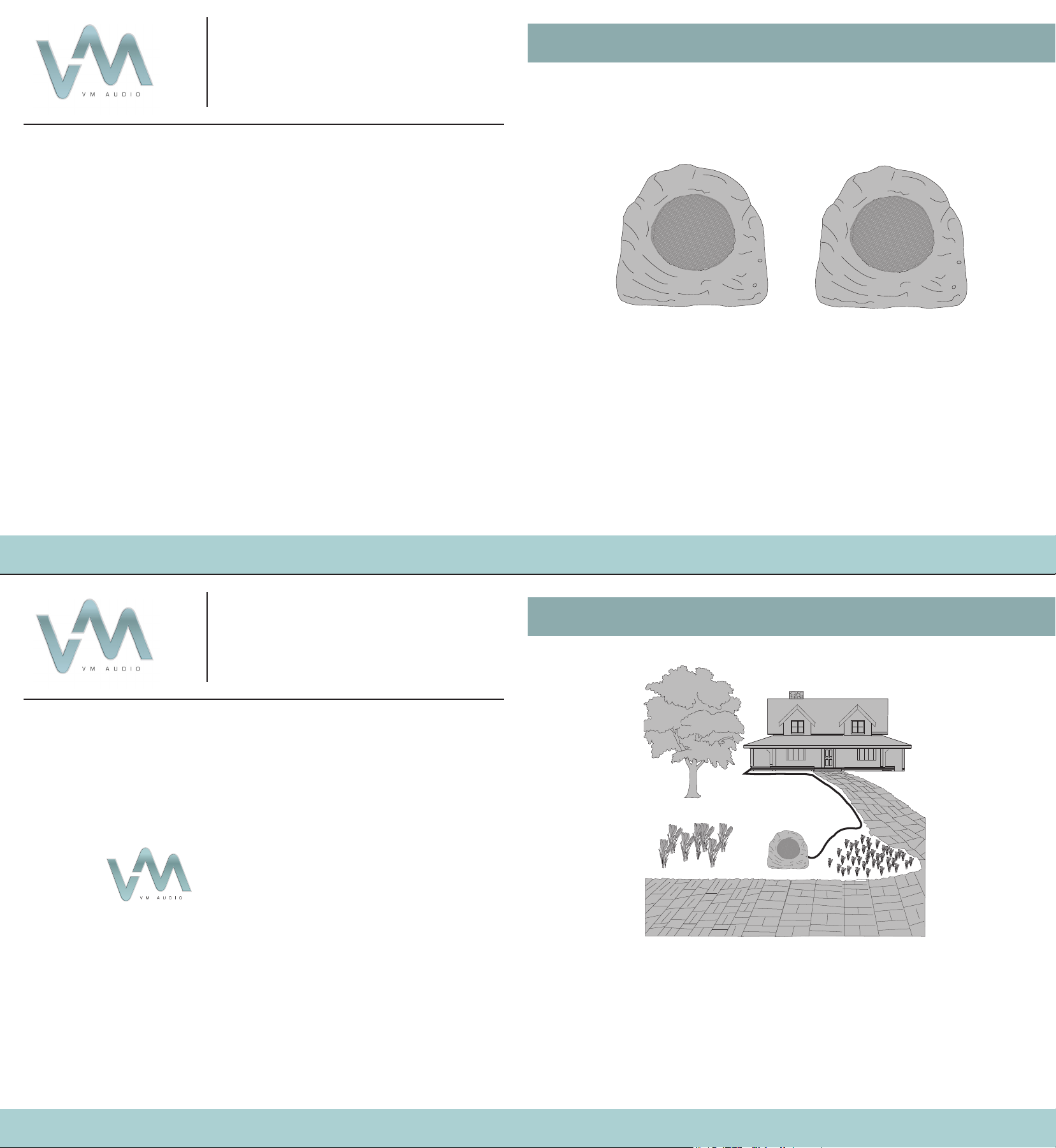
(2) Rock Speakers
2013 COLLECTION
ROCK SPEAKERS
VM Audio Tech Support
US / Canada
phone: (855) audio-99 / (855) 283-4699
email: help@vmaudio.com
Rev. 1
2. Routing
VMROC6
© VM Audio All rights reserved. All trade names are registered trademarks of
respective manufacturers listed.
1. Choose a permanent location to setup your new VM
Audio outdoor speaker.
2. Pre-route all cables from the amplier to the location of
the VMROC6 rock speakers.
Note: Keep your VM Audio speakers away from the
sprinkler system or an area where water may collect.
3. Installation
5. Troubleshooting
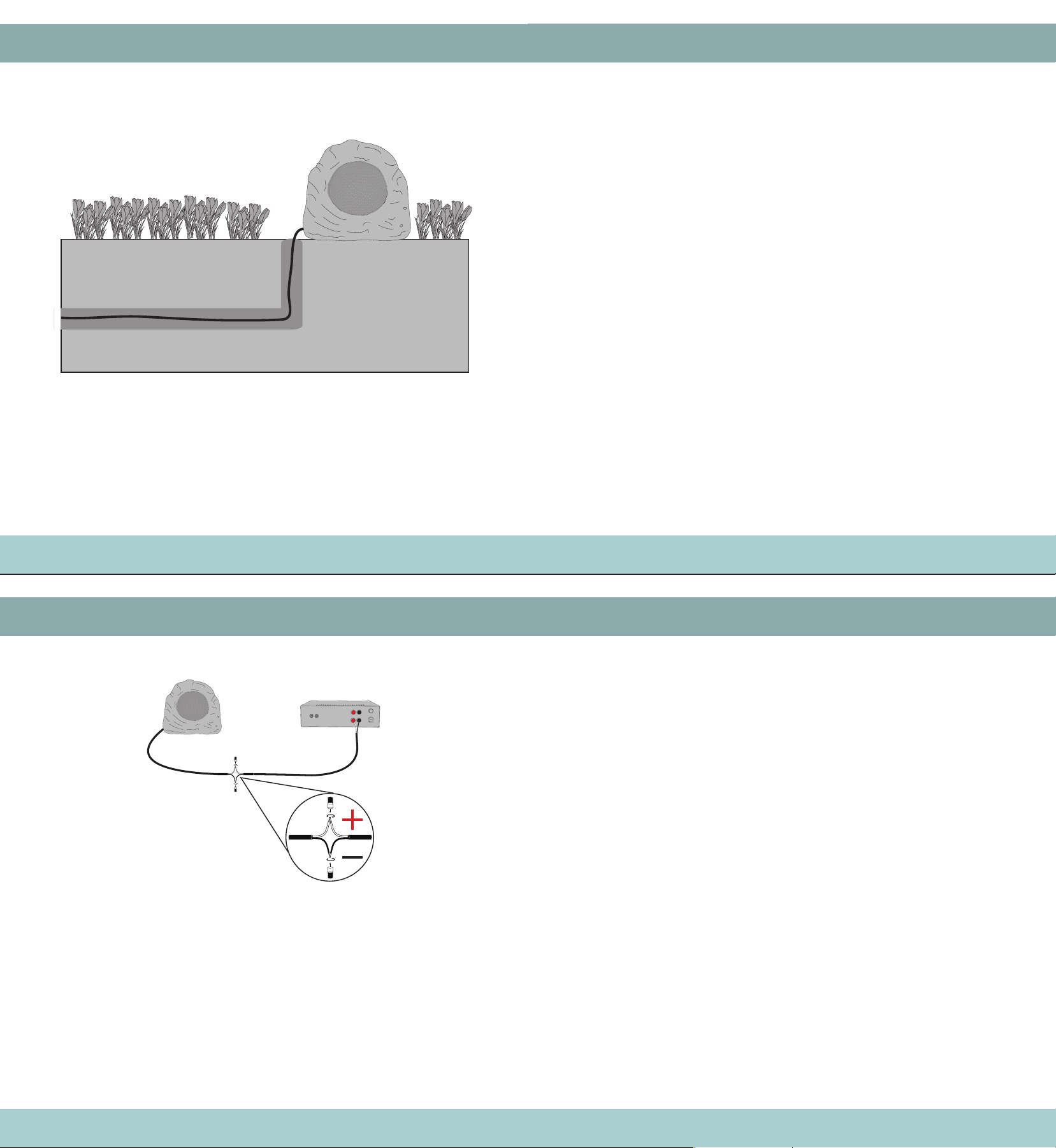
1. Sink the speaker wire 4-6” underground to prevent
accidental tripping over, pulling or other damages.
No Sound
No Sound
from One
Speaker
Distortion
• Check that the speakers are connected to the cable
correctly.
• Check that the speaker cable is connected to the receiver
amplier correctly.
• Check that the receiver amplier is powered “on” at the
mains, is not on “mute”, has no headphones attached and
that the channels used for the exterior speakers (usually A or
B) is in operation.
• Refer to the owner’s guide that came with your receiver
amplier.
• Most initial problems are connectivity, please try a different
connection cable to your outdoor speakers or equipment.
• Check the “balance” control on your receiver amplier.
• Check all connections and cable to the inoperable speaker.
• Disconnect the “working” speaker from the receiver amplier
connection/channel. Switch the cord from the non-operating
speaker from its current connection to the “working” speaker
connection. If the speaker now works, the problem is your
receiver amplier.
• Reconnect as original. Remove the speaker cable at the
“working” speaker directly and connect it directly to the nonworking speaker. If the speaker now works, the problem is
somewhere in the original speaker cable.
• If the speaker still does not work the problem is the speaker.
• Follow same procedure as above for “No Sound”
Warning! Check the intended path carefully to avoid
damaging any pre-laid plumbing or electric wiring.
4. Connections
6. Specications
Speaker Drivers
Woofer
Tweeter
Enclosure
Grill
Frequency Response
Sensitivity
Full Range Co-axial Dynamic
6 1/2” PP Cone/Butyl Surround
1 1/2” Mylar Cone
Fiberglass Composite
Aluminum
60Hz - 20kHz
93dB
Use the color coding of the wires to be sure that positive
goes to positive and negative goes to negative at all the
connection points.
1. Strip off 1/2” of the insulation for each wire.
2. Twist together the two positive or negative wire leads.
3. Push one of the wire nuts onto the ends of the wires
and turn it until it is rmly set.
Power
Impedance
Dimensions
150W RMS / 300 PEAK
8 ohms
10.63” W x 7.87” H x 8.66” D
 Loading...