

VM Audio SRA1500.1, SRA2200.1 Install Manual

SRA1500.1 / SRA2200.1
MONO AMPLIFIERS

CONTENTS INTRODUCTION
Thank you for your interest in VM Audio products.
INTRODUCTION
FEATURES
FUNCTIONS
GETTING STARTED
INSTALLATION
2
2
3
5
7
Our goal is to enhance your listening experience.
The Shaker Series was designed as the economical
solution for a performance craving, casual
consumer. The experts and engineers at VM Audio
have meticulously tested and designed this product
with a reasonable price tag to t any budget. Let
the Shaker Series maximize the value of your
investment.
POWER CONNECTIONS
AUDIO INPUT
LINE OUTPUT
REMOTE CONNECTION
SPEAKER WIRING
CONTROLS
CALIBRATION
TROUBLESHOOTING
SPECIFICATIONS
WARRANTY
8
11
12
13
14
17
18
20
22
23
FEATURES
Class A/B Ampliers
Low Noise and Distortion
Bridgeable Outputs
DC-to-DC PWM Conversion
Unbalanced Inputs
Soft Turn-On
Discrete Signal Processing
Preamp Stereo Outputs
Amplier Protection Circuits
Variable Gain Control
Lowpass Active Crossover
Frequency Variable Crossover
Bass Boost Gain
Remote Bass Adjustment
2
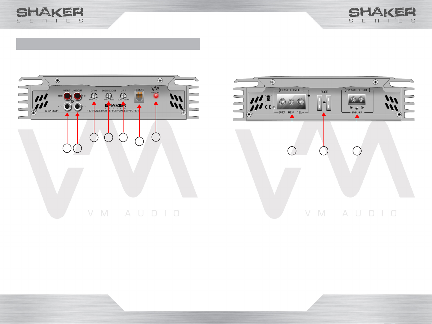
FUNCTIONS
Front Panel
SRA1500.1
Shown
1
3 4 5
2
1. INPUT: Audio Cable Jack Connections
2. OUTPUT: Audio Cable Jack Connections
3. GAIN: Input Signal Adjustment Knob
4. BASS BOOST: Bass Adjustment Knob
5. LPF: Low Frequency Filter Adjustment Knob
6. REMOTE: Remote Bass Knob Cable Plug
7. LED: Power Status LED
7
6
Rear Panel
SRA1500.1
Shown
8
9
8. POWER INPUT: Power Cable Terminal
9. FUSE: In-Line Protection Fuse(s)
10. SPEAKER OUTPUT: Speaker Wire Terminal
10
3 4

GETTING STARTED
Mounting
• Mount the amplier on a at, secure surface.
• Investigate the layout of your automobile
thoroughly before drilling.
• Place the amplier in a location that allows air to
circulate around it to keep it cool.
• If possible, mount the amplier vertically for
proper heat dissipation.
• Avoid mounting the amplier upside-down as
this will not provide adequate ventilation for the
amplier.
• In order to prevent overheating, avoid covering
the amplier with carpet or enclosing it behind
the interior panels.
• If the amplier is installed in a tight area, it must
have at least a 1-inch air gap all around for
proper cooling.
Warning!
• Be aware of gas tanks, gas lines, hydraulic lines
and electrical wiring when drilling mounting holes
to prevent serious or life threatening injuries.
• Do not leave the amplier unmounted in order to
prevent the unit from ejecting like a projectile in
the unexpected event of an accident.
• Do not mount the amplier on top of wires or
metal surfaces in order to prevent electrical
short circuit or a re.
• Never mount the amplier in the engine
compartment.
Wiring
• Before you begin routing and connecting the
power wires, disconnect the negative ground
cable from the vehicle’s battery.
• Install and connect the highest possible wire
gauge the amplier’s terminal will accept (1/0
GAUGE) for both power cables (+12V and GND).
• Install an in-line fuse into the positive (+) wire 18
inches away from the car battery. It should be
the same rating as the amplier’s internal fuse(s)
• Route all power and speaker wires inside the
vehicle toward the amplier prior to mounting it.
• Avoid routing electrical wires where they are at
risk of getting pinched.
• Use rubber or plastic grommets to protect any
wires when routed through metal.
• Route the power cables through one side of
the vehicle while routing the RCA audio cables
through the other side.
• The ground connections should be as short as
possible and always be connected to chassis
metal. Chassis ground connection should be
clean, rust free, unpainted and as close to the
amplier as possible.
Warning!
• Disconnect the negative (-) battery terminal
before routing cables and wires to prevent
electrical shorts.
• Never route wires underneath the vehicle.
• Do not run wires through sharp edges.
• Always turn off amplier(s) before making any
type of connection.
5 6
 Loading...