

VM Audio ECD1200.1, ECD3300.1, ECD2500.1, ECD1500.1, ECD4200.1 Install Manual
...
ECD1200.1 / ECD1500.1 / ECD2500.1
ECD3300.1 / ECD4200.1 / ECD5400.1
MONO AMPLIFIERS

CONTENTS
INTRODUCTION
FEATURES
FUNCTIONS
GETTING STARTED
INSTALLATION
POWER CONNECTIONS
AUDIO INPUT
LINE OUTPUT
REMOTE CONNECTION
SPEAKER WIRING
CONTROLS
CALIBRATION
TROUBLESHOOTING
SPECIFICATIONS
WARRANTY
2
2
3
5
7
8
12
13
14
15
18
19
21
23
25

2
INTRODUCTION
You have just purchased a product from VM Audio’s
Encore Series. As one who demands only the best from
what life offers, you expect luxury and comfort from
your purchasing choice. The Encore Series is designed
to satisfy that need and continue to impress. From
years of experience and unending passion, the experts
at VM Audio have meticulously designed and tested
each product to ensure sounds so true and so clear, it
feels like a live performance. Please read through the
installation instructions and follow carefully; ask for the
help of a certied installer if necessary. When properly
installed, the Encore Series product will perform at its
optimum presentation awlessly for years to come. The
professionals hear what was intended by the artists;
now, so can you.
• Mono Power Subwoofer Car Amplier
• Hyper-Digital Class D Design
• Exclusive High-Cycle DC-to-DC PWM Conversion
• Sophisticated Noise Free Single Star Ground System
• Low Noise Buffered Line Level Input Stage
• Ultra Low Distortion Multi-Stage Signal Processing
• Regulated Synergistic High Voltage Rail Performance
• Side-to-Side Air Flow Thermal Cooling Ventilation
• Second Order Linkwitz Riley Active Filter Processing
• Efcient High Power Switch-Mode Amplier Stage
• SelfGuard Protection
• Turn-On Outow Limiting Current (VM Audio exclusive)
FEATURES
3
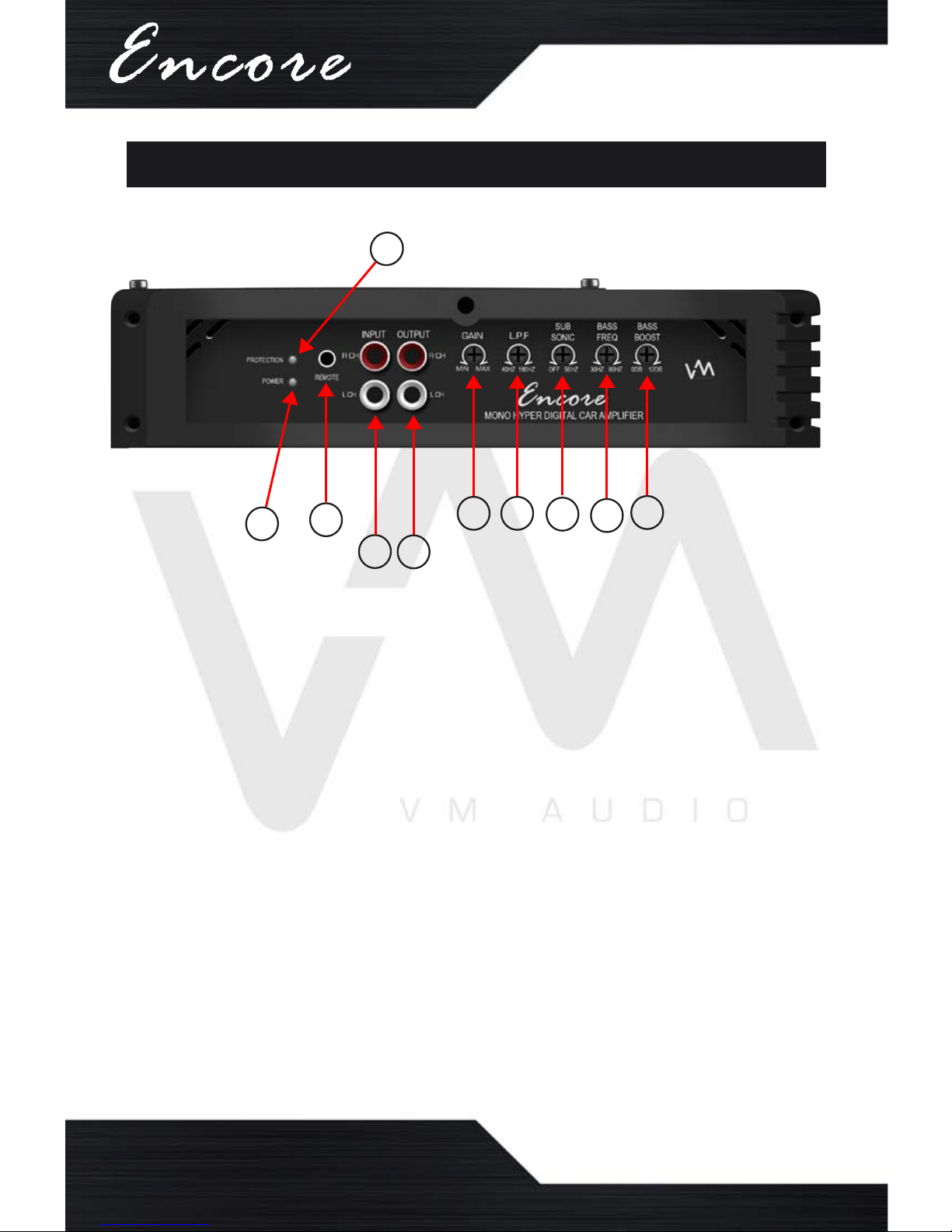
FUNCTIONS
Front Panel
1. INPUT: Audio Cable Jack Connections
2. OUTPUT: Audio Cable Jack Connections
3. GAIN: Signal Strength Level Adjustment
4. LPF: Low-Pass Frequency Filter Setting
5. SUBSONIC: High-Pass Filter Setting
6. BASS FREQ: Low-Pass Filter Setting
7. BASS BOOST: Bass Adjustment Knob
8. BASS REMOTE: Remote Jack Connection
9. POWER LED: Power Status Notication
10. PROTECTION LED: Protection Notication
1
2
3 4
5
6
7
8
9
10
4
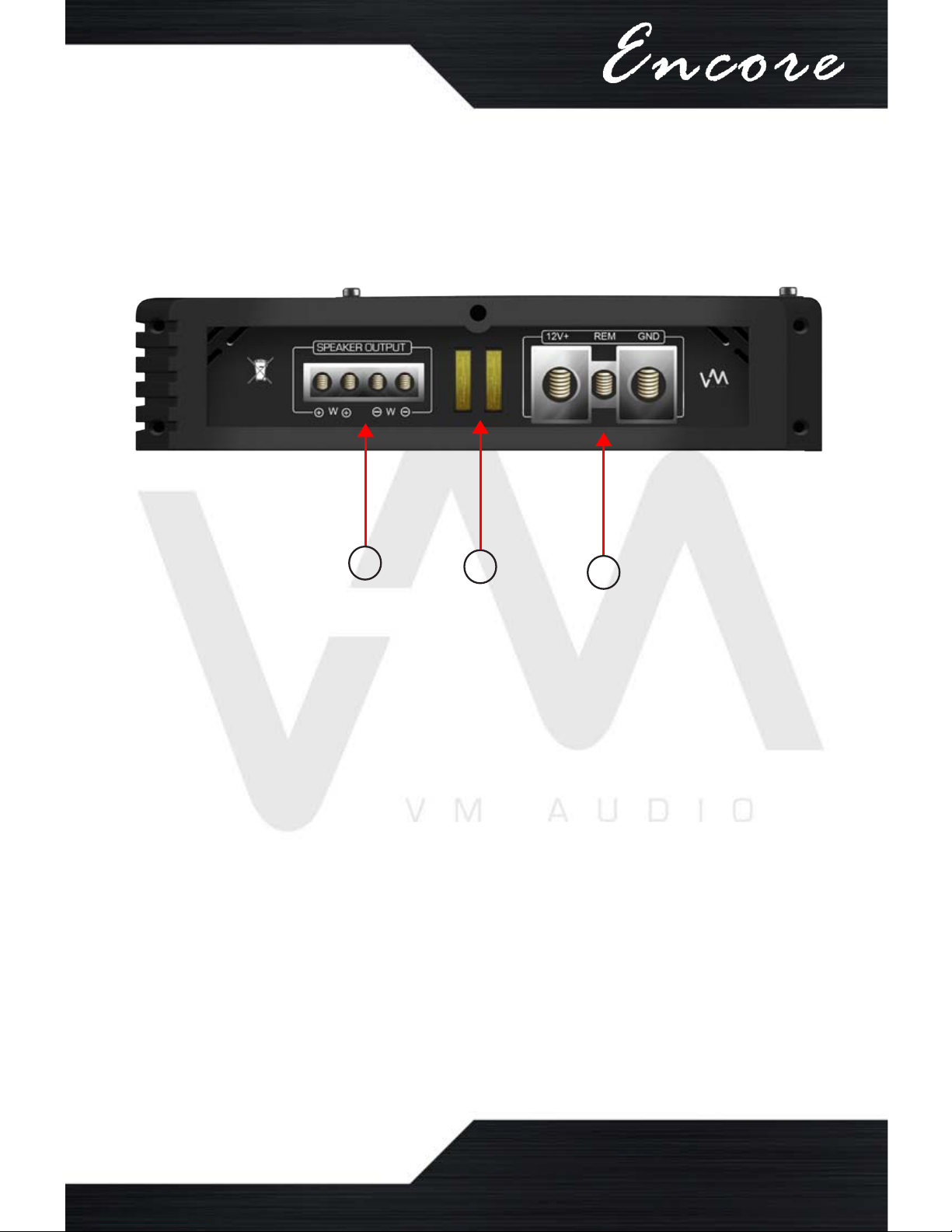
Rear Panel
11. SPEAKER OUTPUT: Speaker Wire Terminals
12. FUSE: In-Line Protection Fuses
13. POWER INPUT: Power Cable Terminals
11
13
12

Mounting
• Mount the amplier on a at, secure surface.
• Investigate the layout of your automobile
thoroughly before drilling.
• Place the amplier in a location that allows air to
circulate around it to keep it cool.
• If possible, mount the amplier vertically for
proper heat dissipation.
• Avoid mounting the amplier upside-down as
this will not provide adequate ventilation for the
amplier.
• In order to prevent overheating, avoid covering
the amplier with carpet or enclosing it behind
the interior panels.
• If the amplier is installed in a tight area, it must
have at least a 1-inch air gap all around for
proper cooling.
Warning!
• Be aware of gas tanks, gas lines, hydraulic lines
and electrical wiring when drilling mounting holes
to prevent serious or life threatening injuries.
• Do not leave the amplier unmounted in order to
prevent the unit from ejecting like a projectile in
the unexpected event of an accident.
• Do not mount the amplier on top of wires or
metal surfaces in order to prevent electrical
short circuit or a re.
• Never mount the amplier in the engine
compartment.
5
GETTING STARTED

6
Wiring
• Before you begin routing and connecting the
power wires, disconnect the negative ground
cable from the vehicle’s battery.
• Install and connect the highest possible wire
gauge the amplier’s terminal will accept (1/0
GAUGE) for both power cables (+12V and GND).
• Install an in-line fuse into the positive (+) wire 18
inches away from the car battery. It should be
the same rating as the amplier’s internal fuse(s)
• Route all power and speaker wires inside the
vehicle toward the amplier prior to mounting it.
• Avoid routing electrical wires where they are at
risk of getting pinched.
• Use rubber or plastic grommets to protect any
wires when routed through metal.
• Route the power cables through one side of
the vehicle while routing the RCA audio cables
through the other side.
• The ground connections should be as short as
possible and always be connected to chassis
metal. Chassis ground connection should be
clean, rust free, unpainted and as close to the
amplier as possible.
Warning!
• Disconnect the negative (-) battery terminal
before routing cables and wires to prevent
electrical shorts.
• Never route wires underneath the vehicle.
• Do not run wires through sharp edges.
• Always turn off amplier(s) before making any
type of connection.

7
INSTALLATION
1
2
3
Mark the mounting
screw holes to be
drilled with a marker.
WARNING! Be aware of gas tanks, gas lines, hydraulic
lines and electrical wiring when drilling mounting holes
to prevent serious or life-threatening injuries.
Drill the holes on the
marked spots with an
electric drill.
Secure the amplier
with screws using a
phillips screwdriver.
Make sure to mount the amplier in a location
where there is enough room to have access to the
knobs and terminals.
8
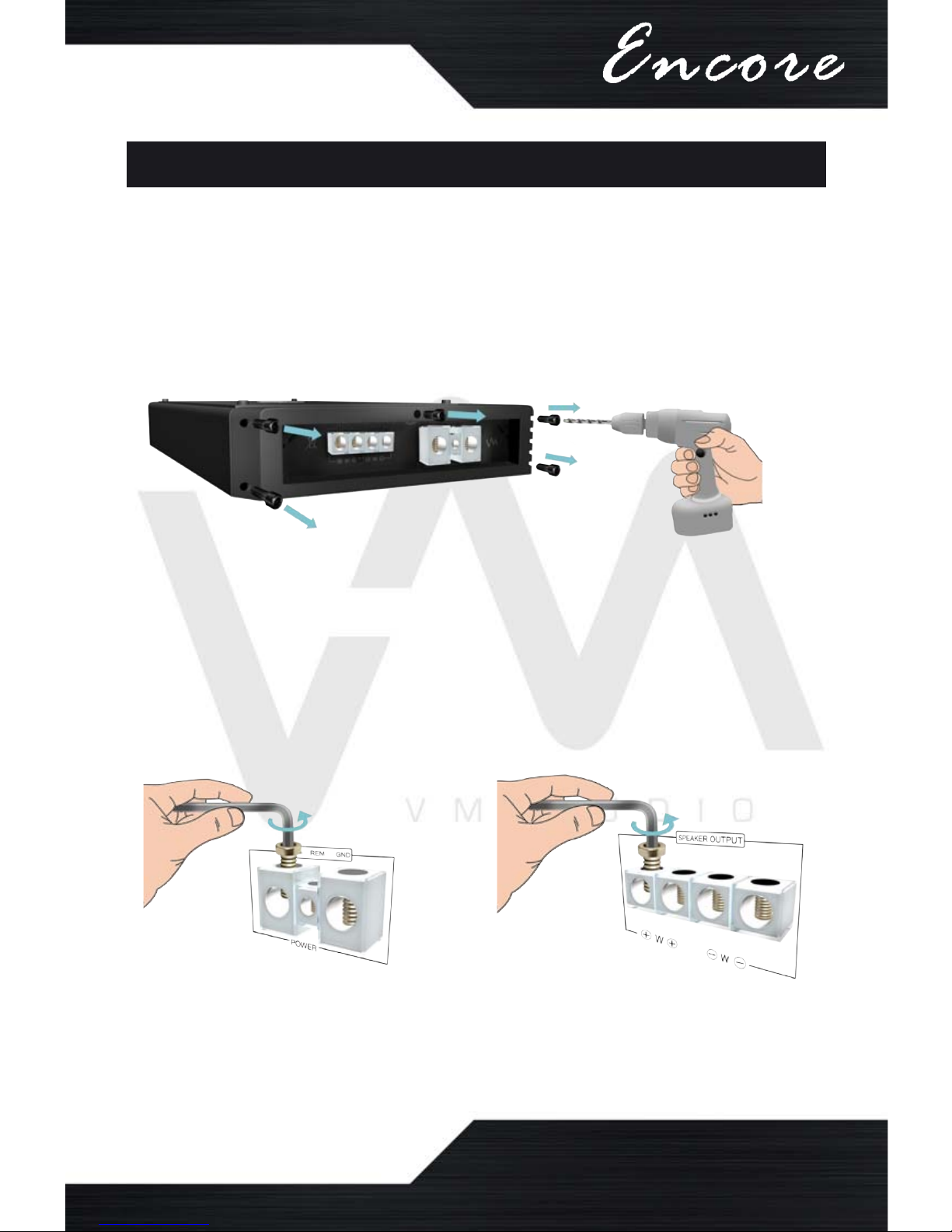
POWER CONNECTIONS
Before you begin, carefully remove the speaker
and power terminal end cap from the amplier by
removing all ve screws.
Prepare the terminals to connect the cables and
wires by loosening and backing out all screws
from the power and speaker terminals.
 Loading...