

Page 1
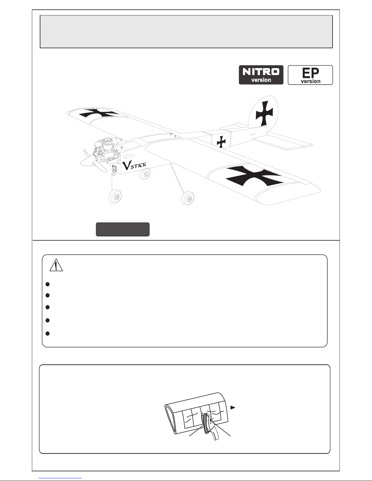
VSTICK 40
Before beginning assembly,please read these intructions thoroughly.
Photograph is nitro version
INSTRUCTION MANUAL
UNDER SAFETY PRECAUTIONS
This radio control model is not a toy!
It is highly recommended that first-time builders seek advice of experienced modelers before beginning assembly.
Assemble this kit only in places out of children’s reach!
Take enough safety precautions prior to operating this model. You are responsible for ths model’s assembly and safe operation!
Always keep this instruction manual ready at hand for quick reference, even after completing the assemble.
Taking out liability insurance is recommended.
*SPECIFICATIONS ARE SUBJECT TO CHANGE WITHOUT NOTICE.
The pre-covered film on ARF kits may wrinkle due to variations
of temprature. Smooth out as explained at right.
Use an iron covered with a cloth!
Start at low setting. Increase the
setting if necessary. If it is too high,
you may damage the film.
with cover (cloth)
low setting
1
ALMOST-READY-TO-RLY
ARTF
DANGER
40
Page 2
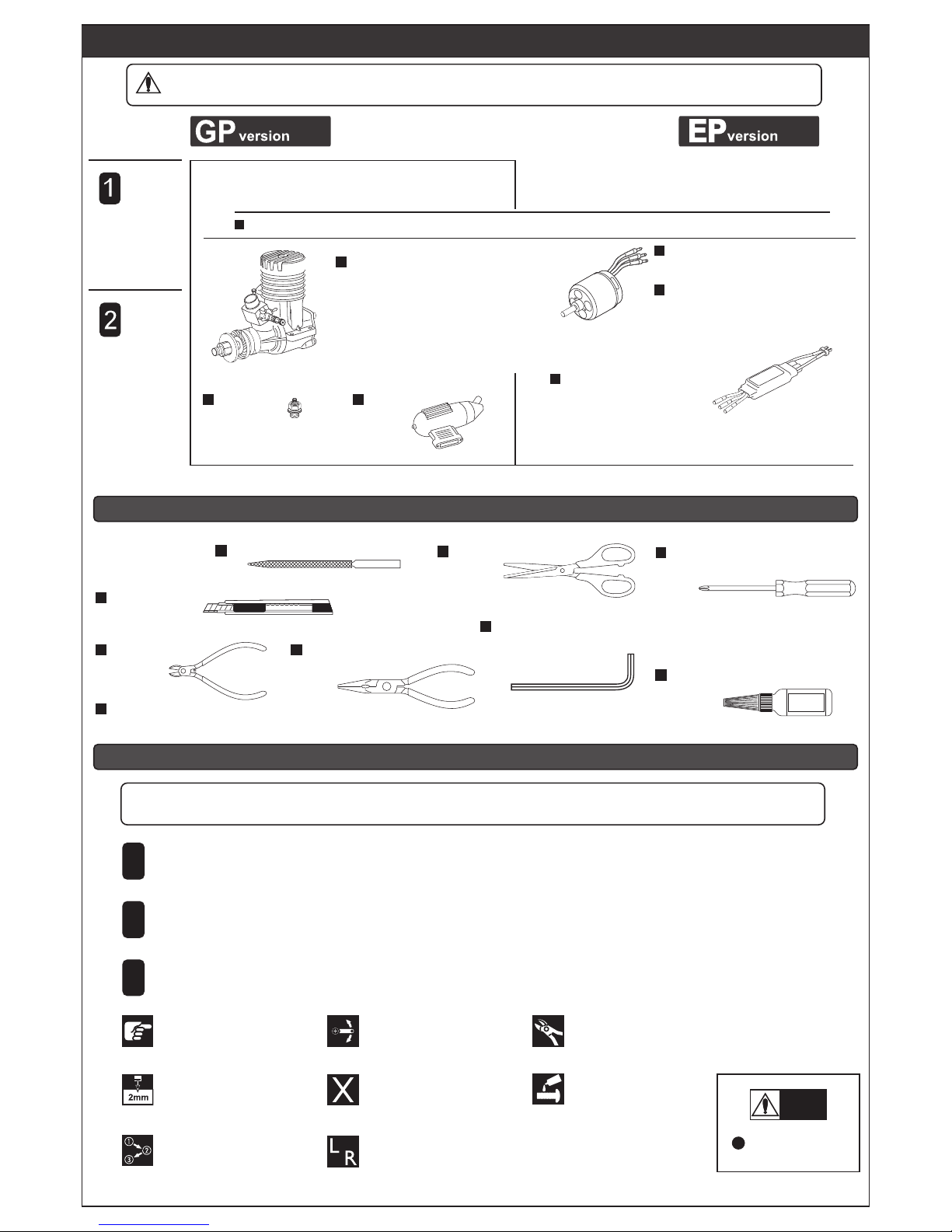
Assemble in the
specified order.
Assemble left and right
sides the same way.
Drill holes with the
specified diametre.
Must be purchased
separately!
Apply threadlocker
(screw cement).
Pay attention here!
Ensure smooth, non-binding
movement when assembling.
Cut off excess.
Do not overlook
This symbol!
Warning!
Symbols used throughout this instruction manual, comprise:
Check all parts. If you find any defective or missing past, contact your local dealer or our VMARSHOP.
Read through the manual before you begin, so you will have an overall idea of what to do.
3
2
1
accepts no responsibility for accidents, damage or breakage if other manufacturers parts are used.
Drill,Bits (2,3,4,6mm)
Cutters Pliers
Long Nose Pliers
Shap Hobby Knife
File
Scissors
Hex Wrench (2, 2.5, 3mm)
Phillips screwdrivers (size: L, M, S)
Threat locker Cement
SCREW
CEMENT
BEFORE YOU BEGIN
TOOLS REQUIRED (Purchase separately!)
CAUTION : For detalls concerning the equlpment Ilsted below (size, make, etc.) check with your hobby shop.
ITEM REQUIRED FOR OPERATION (Not included in kit!)
2
A minimum 4 channel radio for alrplanes (with 5 standard servos),
and nicad or alkaline batteries are required.
4-channel (minimum) radio system for aircraft 4 servos (standard servos).
Please be sure to sure to use servos with enough torque (3.0 - cm minimum).
Y-Harness 2pcs
2-stroke .46~.55
4-stroke .70~.90
Suitable Outer Rotor Motor.
Use outer rotor motor power
between 800~1200w
Motor : KV / 600~650
ESC More than 70A
Muffler
Glow Plug
Radio Set
Engine,
Motor, ESC
Page 3
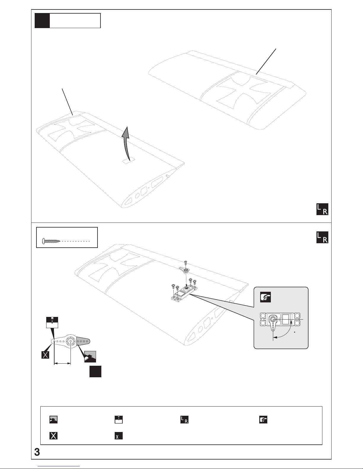
Installing Servo
to the wing
< Top view of left wing >
< Bottom view of left wing >
Aileon servo location
1
Cut off shaded portion.
Must be purchased
separately!
2mm
Drill holes with the
specified diameter.
Assemble as many
time as specified.
4
Assemble left and right
sides the same way.
Pay close attention here!
TP Screw
2 x 10mm
4
approx. 16mm
2mm
x4
Aileron servo arm
position
90
Page 4
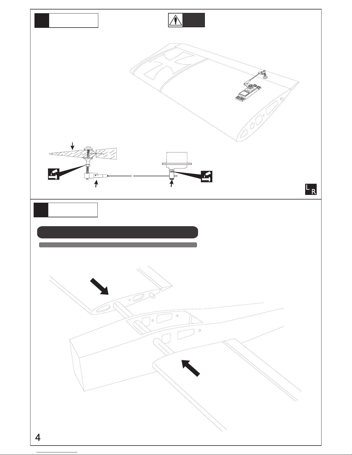
Connecting control
rod to aileron
2
Set all screws securely. If they come off during flight
you will lose control of your aicraft!
Waning!
Typical control horn
installations
Installing the wing
to the fuselage
3
NO GLUE NEDED FOR THIS ASSEMBLY
Aluminum wing joiner tube sizie 16mm diameter and 570mm long
1. Insert the wing joiner tube
to the fuselage
SURFACE CONTROL
EZ CONNECTOR
CLEVIS
Page 5

3 x 15mm
4
Attach wing
to the fuselage
4
Main gear
5
Nose landing gear
6
5
1. Insert the wing tube onto right wing panel
the tighten with the butterfly nut to secure
to the fuselage
2 . same procedure the secure the left wing
panel to the fuselage
4x20xhex bolt
1 wooden washer
1 butterfly nut
Page 6

Main wing
7
Horizontal tail
8
Set all screws securely. If they come off during flight
you will lose control of your aicraft!
Waning!
washer
3mm
security nut
3mm
6
3mm
security nut
3mm
washer
Page 7

Linkage rod
9
Rudder rod
10
Rudder rod
2mm
approx.2mm
Elevator rod
11
SUFACE CONTROL
< Bottom view.>
7
Page 8

Servo
12
Supplied with
the radio.
Supplied with
the radio.
x2
1.5mm
1.5mm
Front
Rudder Control Servo
X
Re
Elevator Control Servo
Rudder Control Servo
Elevator Control Servo
Supplied with the Servo.
Linkage
13
Supplied with the Servo.
approx. 16mm
4x5mm
Linkage Stopper
8
2x10mm
Page 9

Engine Mount
14
4x20mm
Hex bolt
4
Engine Mount
Engine Mount
4x20mm
4x20mm
To Muffler
To Carburetor
Connect the fuel line to the engine
Install the fuel tank to the fuselage
Install the engine
15
washer
3mm
2
3mm
4
Security nut
4
Hex cap bolt
3 x 30mm
3x30mm
Throttle rod
Engine
3x30mm
3mm
3mm
3mm
9
Page 10

Linkage
16
Supplied with the Servo.
Supplied with the Servo.
approx. 16mm
4x5mm
2x10mm
Linkage stopper
2mm
Elevator servo
Linkage
17
Throttle servo
Rudder /steering servo
< Throttle Idling >
Throttle position of TX
approx. 1mm
Throttle servoCarburetor
< Throttle Hi >
< Throttle Stop >
Adjust the throttle input (transmitter throttle stick),
throttle trim movement and the carburetor opening
to the suitable position and screw in the 4x5mm set screw.
10
2mm
2mm
Page 11

1
2
3
4
5
6
Install propeller,
spinner and muffler
18
Securely tighten the nut holding the propeller
for it not come off when the motor is spinning.
If coming off, there is a high risk of injury!
Warning!
Propeller
Motor Mount
19
EP
version
Brushless motor
Motor mount
POWER MODULE WITH FOUR MOUNTING BOLTS
POWER
MODULE
67mm
WASHER
4mm NUT
APPLY THREAT LOCKER HERE
WASHER
APPLY THREAT LOCKER HERE
11
Page 12

ELEVATOR
RUDDER
ALERON
High rate Low rate
75~85mm
Battery
V
M
C of G position
20
GP/EP
version
In order to obtain the CG specified, reposition
the receiver and other equipment
Warning!
Do not fly before confirming the correct location of the CG.
If the CG is incorrect, you lose control of your airplane which leads to accidents!
SURFACE CONTROL MOUVEMENT
Aileron movement
1/5"
6mm
1/3"
10mm
1/3"
10mm
1/5"
6mm
5/8"
16mm
5/8"
16mm
1/3"( 10mm ) up
1/5"( 8mm ) down
1 "( 25mm ) right
1 "( 25mm ) left
1/2"( 16mm ) up
1/2"( 16mm )down
1/5"( 8mm ) up
5/8" ( 16mm ) right
5/8" ( 16mm ) right
1/3"( 10mm ) up
1/3"( 10mm )down
1/3"( 10mm ) down
Aileron movement
12
Rudder movement
Page 13

Fuel Tank
Typical Battery setup for electric version
Typica Fuel Tank setup for nitro version
13
 Loading...