

Page 1

ALMOST
READY
TO FLY MODEL
J3.PIPER
GUB
L4-GRASSHOPPER
ASSEMBLY
& OPERATIONS
MANUAL
Please review
this
manual
thoroughly
before assembling or
operating this model.
Proceeding with
assembly
and use of this
product
indicates
A Remote
Gontrol Model Aircraft is not
a
toy.
lt is
a flying
model
that functions
much like
a
full
size
airplane. lf
you
do not
assemble
and operate this
product properly
you
can cause injury
to
yourself
and others and
damage
prop-
erty. DO
NOT FLY this model
if
you
are not
qualified.
You
are entirely responsible
for
the mechanical,
aeronautical and electrical integrity
of this model
and it's
structure,
control
surfaces, hinges, linkages,
covering,
engine, radio, wiring,
battery
and all other
components.
Gheck all components
before and after
each flight.
Don't
fly until it's
right!
POLYCOTE*EGS
ENHANCED
COVERING
SYSTEM
w
Agreement With
&
Acceptance
of the
following
Liability Disclaimer.
Model
airplanes, model
engines, model
engine
fuel,
propellers
and
related
accessories,
tools and equipment
can be haz-
ardous if improperly
used. Be cautious
and
follow
all
safety
recommendations
when using
your
VMAR
model
airplane.
Keep hands,
tools, clothing
and all
foreign
objects well
clear of
engines when
they are
operating.
Take
particular
care to safe-
guard
and
protect
your
eyes and
fingers
and the
eyes and
fin-
gers
of other
persons
who
may be nearby.
Use only a
good
quality propeller
that has no
cracks or flaws.
Stay clear of the
propeller
and
stay clear of the
plane
of rotation defined
by
the
propeller.
The Manufacturer,
Distributor,
Retailer and/or
other
suppliers of this
product
expressly
disclaim any warranties
or
representations,
either expressed or implied,
including
but
not
limited
to implied warranties
of
fitness
for the
purposes
of
achieving and sustaining remotely
controlled flight. ln no
event
will the Manufacturer, Distributor,
Retailer
and/or other suppli-
ers of this
product
have any obligation
arising from
contract or
toft, or for loss
of
revenue
or
profit,
or for indirect,
special, inci-
dental, consequential
or other damages
arising
from
the use
of
this
product.
ln
purchasing
and/or
using this
product,
the
user
accepts
all
responsibility
for its use
and accepts all liability
associated with such use.
The
Graphics
and Detailing
are
inside
the POLYCOTE ECS/
Page 2
WING ASSEMBLY
Parts
needed
-
Roll of
wing
joiner
tape
-
Right and
left wing
panels
-
Wing
joiner
(also
called dihedral
brace)
Step
1.1 Locate
the wing
joiner
(also
called
Dihedral
brace). Using
a
ruler, determine
the center
of the wing
join-
er and
mark it with a
pencil
as illustrated
in 1B.
Step
1.2 Trial fit the
wing
joiner
into the
wing
panels.
lt
should
insert
smoothly
up
to the center
line as
illustrated
in
SIIETSN
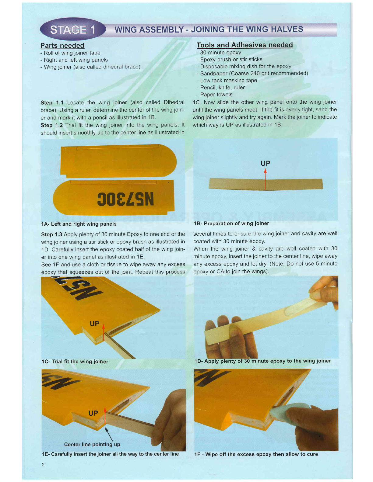
1A-
Left
and
right
wing
panels
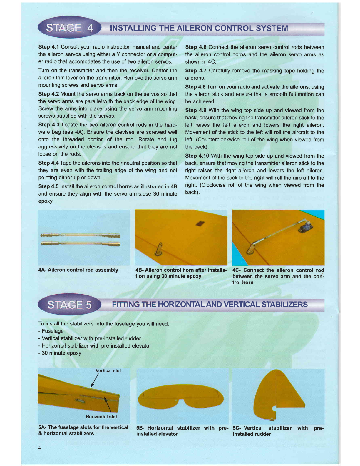
Step
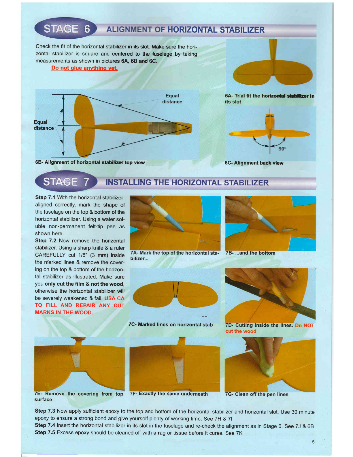
1.3 Apply
plenty
of 30
minute
Epoxy to one end
of the
wing
joiner
using
a stir stick
or epoxy
brush as
illustrated
in
1D.
Carefully
insert
the epoxy
coated
half
of
the wing
join-
er
into one
wing
panel
as
illustrated
in
'lE.
See
1F and use a cloth
or
tissue to wipe away
any excess
epoxy
that squeezes
out of
the
joint.
Repeat this
process
rL
UP
1C- Trial
fit
the
wing
joi
UP
Center
line
pointing
up
1E-
Carefully
insed the
joiner
all the
way to the center
line
2
.
JOINING
THE
WING HALVES
Tools and
Adhesives
needed
-
30
minute epoxy
-
Epoxy brush
or stir sticks
-
Disposable
mixing dish
for the epoxy
-
Sandpaper
(Coarse
240
grit
recommended)
-
Low tack
masking tape
-
Pencil,
knife, ruler
-
Paper
towels
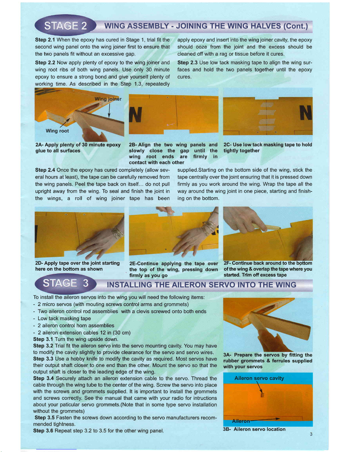
1C. Now slide
the other
wing
panel
onto
the wing
joiner
until the
wing
panels
meet. lf the
fit is overly
tight, sand
the
wing
joiner
slightly and
try again.
Mark the
joiner
to
indicate
which
way is UP
as illustrated
in 18.
UP
1B-
Preparation of
wing
joiner
several
times
to ensure
the
wing
joiner
and cavity
are
well
coated
with 30 minute
epoxy.
When the
wing
joiner
& cavity
are
well coated
with 30
minute epoxy,
inserl the
joiner
to the center
line,
wipe away
any excess
epoxy
and let dry.
(Note:
Do
not
use
5
minute
epoxy
or CA to
join
the wings).
1D- Apply
plenty
of 30 minute epoxy
to the
wing
joiner
n
1F
-
Wipe off the excess
epoxy then allow
to cure
Page 3
WING
ASSEMBLY - JOINING THE WING HALVES
(Gont.)
2A- Apply
plenty
of30 minuta epory 2B-Align the two wing
panels
and 2C- Use low tack masking tape to
hold
gluetoall
surfac6 slowly close the
gap
until the tightly together
:ilg",'iil
"11f"."31"
rirmr' in
Step 2.4 Once the epoxy has cured completely
(allow
sev- supplied.Starting on
the bottom side of the wing, stick the
eral
hours
at
least), the
tape can
be carefully removed from tape centrally over the
joint
ensuring that it is
pressed
down
the
wing
panels.
Peel the tape back on
itself...
do
not
pull
firmly
as
you
work around the wing. Wrap the tape all the
upright away from the wing.
To
seal and
finish
the
joint
in way
around
the wing
joint
in one
piece,
starting and finish-
the wings, a roll of wing
joiner
tape has been
ing
on the bottom.
Step
2.1
When the epoxy has cured in Stage 1, trial fit the
second wing
panel
onto the
wing
joiner
first
to ensure that
the two
panels
fit without
an excessive
gap.
Step
2.2 Now
apply
plenty
of epoxy to the wing
joiner
and
wing
root ribs of both wing
panels.
Use only
30
minute
epoxy
to
ensure a strong bond
and
give yourself plenty
of
working time. As described in the Step 1.3, repeatedly
apply epoxy
and
insert into the wing
joiner
cavity,
the
epoxy
should ooze
from
the
joint
and the excess should be
cleaned off
with
a
rag or tissue before it cures.
Step
2.3
Use
low tack maskilg tape to
align
the wing sur-
faces and hold the
two
panels
together until
the
epoxy
cures.
3A- Prepare the servos
by
fitting
the
rubber
grommets
&
ferrules
supplied
with
your
seryos
2D- Apply tape over the
joint
starting
here on the boftom as shown
To install
the aileron servos into the wing
you
will need
the
following
items:
-
2 micro
servos
(with
mouting
screws control arms
and
grommets)
-
Two
aileron control rod
assemblies
with
a clevis screwed onto both ends
-
Low
tack masking tape
-
2
aileron
control
horn assemblies
-
2 aileron
extension cables
12
in
(30
cm)
Step 3.1 Turn the wing upside down.
Step
3.2
Trial
fit the aileron servo into the
servo
mounting
cavity. You may have
to modify
the cavity
slightly to
provide
clearance
for
the
servo and servo wires.
Step
3.3 Use a hobby knife to modify the
cavity as
required.
Most servos have
their
output shaft closer to
one end than
the
other. Mount the servo so that the
output shaft is
closer to the leading edge of the wing.
Step 3.4 Securely attach an aileron
extension cable
to
the servo. Thread the
cable through the wing tube
to the center of the wing. Screw the servo into
place
with the
screws
and
grommets
supplied.
lt
is important to install the
grommets
and screws correctly. See the manual that
came
with
your
radio
for
intructions
about
your paticular
servo
grommets.(Note
that in some type
servo
installation
without
the
grommets)
Step 3.5 Fasten
the screws down according to the seryo manufacturers recom-
mended
tightness.
Step 3.6 Repeat step 3.2 to 3.5 for the other wing
panel.
2E-Continue applying the tape over
2F-
Gontinue
back around to the bgttom
the top of the wing,
pressing
down
of
the wing & overlap
the tape
where
you
firmly
as
you go
stafted.
Trim
off excess tape
INSTALLING THE AILERON
SERVO
INTO THE WING
38- Aileron servo location
Page 4
INSTALLING
THE AILERON
CONTROL
SYSTEM
Step 4.1
Consult
your
radio instruction manual
and center
the
aileron
servos using either a Y connector
or a comput-
er
radio
that accomodates the use
of
two
aileron servos.
Turn on the
transmitter and then the receiver.
Center the
aileron trim
lever on the transmitter. Remove
the servo arm
mounting
screws and servo arms.
Step
4.2 Mount
the servo arms
back on the servos so that
the
seruo arms are
parallel
with the
back edge of the wing.
Screw the arms into
place
using the servo arm mounting
screws supplied with the servos.
Step
4.3
Locate the two aileron
control
rods in
the hard-
ware
bag
(see
4A). Ensure the
clevises are screwed well
onto the threaded
portion
of
the rod.
Rotate
and tug
aggressively
on
the
clevises and ensure that
they are not
loose
on the
rods.
Step 4,4Tape
the ailerons into
their
neutral
position
so that
they are
even with the trailing
edge of
the wing
and not
pointing
either up or down.
Step
4.5
Install the aileron control horns
as illustrated in 48
and ensure they align with the
servo arms.use 30 minute
epoxy .
dr*lfl**rd
4A- Aileron
control
rod
assembly
Step 4.6
Connect the aileron servo
control
rods
between
the aileron control horns
and the aileron seryo
arms as
shown in 4C.
Step
4.7
Carefully remove the masking tape holding
the
ailerons.
Step 4,8 Turn on
your
radio and
activate the ailerons, using
the aileron
stick and
ensure that
a smooth full motion can
be achieved.
Step
4.9
With the wing top side up
and
viewed from the
back,
ensure that
moving
the transmitter aileron
stick
to the
left raises the left
aileron and lowers the right aileron.
Movement
of the stick to the left will roll the aircraft to the
left.
(Counterclockwise
roll of the wing when viewed
fr:om
the back).
Step 4.10 With the wing
top side up and viewed from the
back, ensure that moving
the transmitter aileron stick to the
right raises the right
aileron and lowers the left aileron.
Movement
of the stick to the right will roll the
aircraft to the
right.
(Clockwise
roll of the wing when viewed from
the
back).
48-
Aileron control horn
after installa-
tion using
30
minute
epoxy
4G- Connect the
aileron control rod
between
the servo arm and the con'-
trol horn
HORIZONTAL
AN D
VERTICAL
STABI
LIZERS
To
install the
stabilizers
into
the fuselage
you
will need.
-
Fuselage
-
Veftical
stabilizer with
pre-installed
rudder
-
Horizontal
stabilizer with
pre-installed
elevator
-
30
minute
epoxy
Horizontal
slot
5A- The fuselage
slots for
the
vertical
&
horizontal
stabilizers
4
58- Horizontal stabilizer with
installed elevator
pre-
5C- Vertical stabilizer
with
installed rudder
Vertical slot
pre-
Page 5
HORIZONTAL
STABILIZER
Check
the fit
of the horizontal
stabilZer in ibs
sbt Make
sure the hori-
zontal
stabilizer is
square
and centered
to the
fuselage
by taking
measurements
as shown in
pictures
6A,
68 and
6C.
Do
not
glue
anything
yet
6A- Trial
fit the horizor*d
sl*tur in
its
slot
Equal
distance
68- Alignment
of horizontal
stabiliar top view
6G- Alignment back
view
INSTALLING
THE HORIZONTAL
STABILIZER
Step 7.1 With
the horizontal
stabil2er-
aligned
correctly,
mark the
shape
of
the fuselage
on the top
& bottom
of the
horizontal
stabilizer.
Using
a
water
sol-
uble non-permanent
felt-tip
pen
as
shown here.
Step 7.2 Now
remove
the horizontal
stabilizer.
Using a sharp knife
& a ruler
CAREFULLY
cut 1/B'
(3
mm) inside
the marked
lines & remove
the cover-
ing
on the top
& bottom
of the horizon-
tal stabilizer
as illustrated.
Make
sure
you
only cut
the film & not
the wood,
otherwise
the horizontal
stabilizer will
be severely
weakened
& fail.
USA
CA
TO FILL
AND
REPAIR
ANY
CUT
MARKS
IN THE
WOOD.
7C-
Marked lines
on horizontal
stab
7E- Remove
the
covering from
top
surface
Step 7.3 Now
apply sufficient
epoxy to the top
and bottom of the horizontal
stabilizer
and horizontal
slot. Use 30 minute
epoxy to
ensure a strong
bond and
give
yourself plenty
of working
time. See ZH & 7l
Step 7.4 Insert
the horizontal
stabilizer in its slot in
the fuselage and re-check
the alignment
as in Stage
6. See 7J & 68
Step 7.5 Excess
epoxy should
be cleaned off with a rag
or tissue
before it cures. See 7K
78- ...and
the bottom
bilizer...
-
Exactly
the
same unde
Page 6

7H-
Apply
plenty
of
30 minute
ePory
slot
into
the
horizontal
FITTING
THE
VERTICAL
STABILIZER
Step
8.1
Check
the
fit of the
vertical stabilizer
in its slot.
Make sure
that
it is
square
to the
horizontal
stabilizer
and
fuselage.
See
8A
Step
8.2
Mark the
shape
of
the
fuselage
on
the
left &
right sides
of
the vertical
stabilizer
using
a
felt-tip
pen.
See
BB
Step
8.3
Now
remove
the vertical
stabilizer.
Using
a sharp
knife
&
ruler
CARE-
FULLY cut
just
1iB"
(3mm)
inside
the
marked
lines
(see
8C) and
remove
the cov-
ering
on both
sides
of
the
fin
(see
BD),
just
as
you
did
with
the
horizontal
stabi-
lizer,
making
sure
you
only
press
hard enough
to cut
the covering,
not the
verti-
cal
stabilizer.
USA
CA
TO
FILL AND
REPAIR
ANY
CUT
MARKS
lN
THE
WOOD.
88-
Mark both
sides
of
the
vertical
stabilizer
8E-
Apply
plenty
of 30
minute
epoxy
6
8G- Garefully
cut
through
the
cover'
ing.
Do
NOT cut
the
wood
8F- Slide
the stab
into
Place
&
remove
excess
epoxy
8A-
Trial
fit the
vertical
the
fuselage
slot
SG- 90
degree
angle
between
the
hor'
izontal
and
vertical
stabs.
Step
8.4 Now apply
sufiicient
epoxy to both
sides & the
Step 8.5
Insert the
vertical stabilizer
in its
slot in the fuse-
bottom of the
vertical stabilizer
as illustrated
in 8E. Use
30 lage and
re-check
the alignment.
Excess adhesive
should
minute epoxy
to ensure
a strong bond
and
give yourself
be
cleaned off
with a rag or
tissue before
it cures.
7l-
Apply
plenty
of
30
minute
epory
to
the
horizontal
sta'
7J- Slide
the
horizontal
stabilizer
into
place
7K-
Wipe
off excess
30
minute
ePoxY
stabilizer
jnto
8D-
Remove covering
from both
sides
Page 7

INSTALLING
THE LANDING
GEAR
matn
INSTALLING
THE TAIL WHEEL
10D-
Use two straps and four 10x2mm
screws to mount the main landing
gear
assembly
--
Rudder
steering wire
1/
E
f
i:
The J3
piper
cup has a tail
dragger
gear
configuration
using
a
tail wheel
and main
landing
gear.
FITTING
THE MAIN LANDING
GEAR
ldentify the main landing
gear
components shown below
-
2
pre-assembled
main landing
gear
-
Pre-assembled tail wheel
-
Three
3x8
[mm]
bolts
with
nuts and washes
NOTE: In
some
markets
this model is
supplied
with
fairings for the main
landing
gear.
lf
your
model was
supplied with fairings
and
you
wish
to install
them
please
use the fasteners
provided
and consult the
picture
in
Stage 9.
ldentify
the tail wheel
components
per
illustration
11A:
-
1 tail wheel
assemblv
i:.
...1
,
i.
i
tF.!..i,r,'.-:-i
.,.'
..,
i .-
118 - Insert
the rudder steering wire
into the
steeing
guide
tube on the bot-
tom of the rudder.
Pre-bent
main landing
gear
wires
10A- Main landing
gear
components
lt.
i
10C- Insert the
pre-bent
main landing
gear
into the fuselage
6;
dJ
gc
s+
qs
el Mounting Bracket
11A- Tail wheel assembly
mounting
11D
-
Trim off
the excess rudder
steer-
ing wire.
\
\
11C
-
Screw the tail wheel
bracket to
the
fuselage.
Page 8

INSTALLING THE
ELECTRIC MOTOR AND ESC
Electric motors vary in size, styles and mounting method.
Always refer to the mounting instructions applicable to
your
motor.
We illustrate
the
general
installation
procedure
here utiliz-
ing
the
recommended
standard
VMAX Brushless Motor
#VMM
111818VM
(factory
ref
#Va241o-12)and
VMAX 15
Amp
Speed Control
with BEC
(#VMC-12OB15VC).
lf
you
have
purchased a pre-assembled
VMAX
power
mod-
ule assembly consisting
of firewall, motor and speed control
you
may skip
124
through
12E.
12A-VMAX Brushless
111818VM
(
factory ref
)recommended
ae
rFr
a
12B. A special
pre-drilled
firewall
is
included for mounting the recom-
mended VMAX motor. A blank
firewall
is
also
provided
for other motor instal-
lations
12E- Mount
the
Speed Control to the
back of the firewall so
that the metal
heat sink faces the ventilation
hole
(forward).
Secure in
place
with
a
tie-
wrap
12H- Mount the
pre-assembled
fuse
holder/switch to the fuselage front
former
12G- Securely mount the
aluminum
motor backing
plate
to the
firewall
using 4 , bolt & washer sets
provided.
Tighten the bolts securely and apply
thread locker such as
Pacer Z-42
(Blue)
a
I
-
a
a
12F- Assembled Power
Module
com-
plete
with firewall, motor & speed con-
trol
Motor #VMM
#
Va 2410-12
12D- Route
the
motor wire to
the
back
of the
firewall
as shown
12G- Fuselage
front
former
12J- Install four 3x50
[mm]
bolt
sets
(supplied).
Bolt-washer-former-wash-
er-nut
(front).
Tighten the nuts secure-
ly & apply thread locker
B
il
121- Test fit a 20 Amp automotive
spade fuse into the fuse holder/switch
and then
REMOVE THE FUSE
12K- Thread
four 3 mm nuts onto the
bolts as shown. The nuts should be all
be evenly spaced at .875 in.
(22
mm)
from
the firewall
12L- Place four 3 mm washers on the
bolts & then
position
the assembled
power
module. Secure in
place
with
four more 3 mm washers & nuts.
Tighten snugly
Page 9

Fuse
holder/Switch.
The
fuse is
be inserted
only when
flying
or
testing.
ALWAYS
REMOVE
THE
FUSE
WHEN
NOT FLYING
OR
TESTING
WARN]NG
WRONG
CONNECT]ONS
W]LL DESTROY
COMPONENTS.
Brushless
motor VMAX
#VMM
111818VM(
factory ref
# Va 2410-121
12M-
Typical
wiring
for electric
power
system.
LIPO battery
WARNlNG
BEFORE
PLUGG]NG
TH]S
CONNECTOR
INTO
THROT-
TLE
CHANNEL
OF RECEIV-
ER ENSURE
PLUG
IS
COR.
RECTLY
POSIT]ONED
TO
Electronic
Speed
Controler
(ESC)VMAX
#VMC-120815VC (factory
ref
# VMX 18)
t
MArcH
YouR
R
ER
&
I
sERVo wl
I
Connect
to receiver
INSTALL
THE
COWL AND
PROPELLER
Install
and align
the
cowl using
the four
cowl mounting
screws
provided.
The
screws
pass
through
the sides
of the
cowl
and into
the tabs
on the front
of the fuselage.
Step 13.1
Cut
card stock
strips
about 112
x
5"
(12x120
mm).
Use low
tack masking
tape
to
position
the
strips
as
shown in
138.&
13C
Note
that
the tape is
applied
towards
the rear
of the
strips
and
that
the front
of the
strips
overlap
the cowl
mounting
tabs
at the front
of the fuselage.
Step
13,4
Mark
the mounting
hole
locations
with
a DOT
per
l3C.Without
moving
the
cowl, carefully
hold
each
strip flat
against
the
cowl and
working
around the
cowl
one
strip at
a time, drill
a 5164 in.
(2
mm)
hole
through
the dot,
the cowl
and
the mounting
tab.
See
1 3E.
Step
13.5 Hold
the
cowl in
place
using
four
2x10
[mm]
screws.
Carefully
remove
the
strips
and
all masking
tape.
Step 13.6
With
the
BATTERY
&
FUSE
REMOVED
securely
install the
propeller.
Double
check
your
work
and
ensure
that
the
propeller
is
securely
attached
and
will not
come
off.
13A-
Pre-painted
cowl
supplied
Step 13.2
Mark
each strip with
a
dot
in
the center
of
each
cowl mounting
tab
as shown in 13C.
Step
13.3
Slide the
cowl into
place
to completely
cover the
mounting
tabs
on the fuselage
&
such that
the strips
are
outboard
of
the
cowl as shown
in 13D.
Align
the cowl
so
that
the motor
shaft
is centered.
Secure
the
cowl in
position
with low
tack masking
tape.
13C-
Mark
the strip
with
a dot
at the
center
of each
cowl mounting
location
138-
Gard
stock
strips
overlying
the
cowl mounting
tabs
on the left
and
right
side
of the fuselage
13D-
Position
the
cowl
over
the
mounting
tabs.
Note
the strips
are
outboard.
Align
& center
with
respect
to
the motor
shaft
9
f1l4
in..(8mm)
Page 10

fuselage
13E-
Do not
move
the
cowl.
Drill
through
the dot,
the cowl
and all
four
mounting
positions
13F-
Secure
the
cowl
into
place
with
four
2x10
[mm]
screws
13G-
With
the
securely
peller
install the
pro-
Lightweight
laser
cut
horns are
used
on
this
model
(see
14A).
Remove
cov-
ering
from
the
mounting
locations.
Attach
firmly
with
30
minute
Epoxy as
shown
in 148,
14C
and
14D.
ELEVATOR
AND
RI.JDDER
CONTROL
HORNS
a..
i
FITTING
THE
144-
Typical control
horn
assembly
*o
15C-
Note the
orientation
and
posi-
tions
of the
two
servos
in the
servo
tray
\*.,
i:
14D-
Rudder
control
horn location
I
15A-
Servo tray
NOSE
-'='.-Gl\
148-
Typical
control
horn after
instal-
lation
15D- Connect
the elevator
and
control
rods
to the
servo
arms
"*f{"
14C-
Elevator
control
horn location
:":
INSTALLING
THE SERVOS
Install
the
rubber
servo
grommets
& brass
ferrules
supplied
with
your
radio
equipment.
The
two servos
that control
the elevator
and
rudder are
to
be
installed
in the seryo
tray
mounted
in the fuselage.
Remove
the
servo
tray
from
the
fuselage,
mounting
the
servos
to
the seryo
tray as
shown
in 15Aand
'15B.
And then
install
the servo
tray
back
into
the fuselage
as
shown
in
15C. Hook
up
the
control
rods
as shown
in
15D.
€
NOSE
elevator
rodr
L.-
; t
158-
Note the
orientation
and
posi-
tions of
the
elevator
and
rudder con-
trol
rods
10
F
*
t
rud
---rludder
rod
Page 11

CONNECTING
THE PUSHRODS
TO
THE
RUDDER
AND ELEVATOR
SERVOS
Consult illustration 164&
carefully connect
the control rods
to the
servos using
the
clevises
as shown.
CONNECTING
THE
Connect the
elevator servo to
the receiver
and turn
on
your
transmitter
& then
vour
receiver.
Center the transmitter
16A-
Center the
servo control
surface
and
then connect the
control rods
to
the servos
using the clevises
as
shown
PUSHROD
TO THE
ELEVATOR
stick and trim. Adjust
the seryo
arm and clevises
to center
(not
up, not
down) the
elevator as shown in 17A
and 17B.
&
\:
'+.
control horn
shown in
CONNECTING
THE PUSHROD
TO
THE RUDDER
Connect the
rudder
seryo to the receiver
and turn
on
your
transmitter
&
then
your
receiver.
Center
the
trans-
mitter
stick
and trim. Adjust
the
servo
arm and clevises
to center
(not
left,
not right)
secure the rudder
as shown
in 18A.
17B- Hold
the elevator
at neutral
(not
up, not
down). Rotate
the clevis
to adjust
the
overall length.
Then use the
clevis screw
to attach the
clevis
to the control
horn. The
clevis
screw requires
a 5164 in.
(2mm)
hole. Secure
the
screw with
thread lock
ADJUST
CONTROL
18A-Hold
the rudder
at neutral
(not
left,
not right).
Rotate
the clevis
to adjust
the overall
length.
Then
use the
clevis
screw to
attach the
clevis to the
control
horn. The
clevis
screw requires
a 5164 in.
(2mm)
hole.
Secure the
screw
with
thread
lock
SURFACE
THROW
LIMITS
-
From
the
control horn
end, move
the
control rod/clevis
fur-
ther
out on the horn
(away
from
the
control
surface).
Always
confirm
that the
clevis is firmly
attached
after mak-
ing
any
adjustment.
Adjust
the
deflection
of the
control
surfaces to
match
the
specifications
on
page
12. You
can
reduce
the amount
of
throw by
doing
either or both
of the
following.
-
From
the
servo end, move
the
clevis
to a hole in
the
servo
arm
that is
closer to the
servo output
shaft.
11
Page 12

FINAL RC
SET-UP
Before
starting
the
final
set-up
of the model, switch
on the
radio
and ensure
that all trims are
in their
neutral
positions.
Check
that the ailerons, elevator
and
rudder are centered.
lf
any adjustments
are
needed,
do these
by uncoupling
the relevant
clevis
and
turning it clockwise
to shoften the linkage or
counter - clockwise
to
lengthen it.
Only
when each
control surface
has been centered mechanically
in
this
way
should
you
begin adjusting
the surface
movement
(or
throw)
Now
confirm
that the control surfaces
are moving
in
the correct direction.
Use the servo
reversing
switches on
your
transmitter to
reverse the
direc-
tion of a
servo if necessary.
The most
popular
transmitter
mode
(with
the throttle on
the left, with
ailerons and elevator on
the right)
is
shown
here.
We have
assumed
throughout most of these instructions that
your
J3 Piper cub
is
being
powered
by an
electric motor and
Electronic Speed Control
with BEC.
Stage
21
applies only
if
you
are using
glow power.
Step 21.1
Consult
your
radio manual for instructions about
hooking
up
your
receiver
battery,
receiver
and switch
harness.
Step
21.2 Wrap the
battery
pack
securely in
foam
suitable
for
RC equipment and wrap the
foam insulated
pack
in
a
plastic
bag or cling wrap. Position the battery
pack
under the fuel tank
or nearb
INSTALLING
THE RECEIVER
Step
22.1
Consult
your
radio manual'for instructions
about
hooking up
your
receiver.
Step
22.2Plan where
you
are
going
to
put
the receiver with
consideration
for routing the
antenna safely.
Step
22.3 Wrap the receiver securely
in
foam suitable
for
RC
equipment and
wrap the
foam insulated receiver in a
12
INSTALLING THE RECEIVER BATTERY(G|ow Engine
Only)
Step
21.3 Thread the battery
pack
connector back
through
from beneath the
fuel tank to the radio compartment by
passing
the battery connector
through an opening beside
or beneath
the fuel tank.
Step 21.4 Connect the battery
connector to
your
radio
sys-
tem according to the radio
manual.
PLEASE NOTE THAT A FUEL TANK IS NOT
SUPPLIED
WITH THIS MODEL.
plastic
bag or cling wrap.
Step
22.4
Generally
in the absence of specific
instructions
from
the
radio manufacturer, it is recommended that the
receiver
should be
placed
where
it is
least
likely to have
impact during a crash.
Keep
the battery
pack
and other
heavy loose items ahead of
the receiver.
Page 13

CONFIRM
RADIO
Carefully
review
how
your
Electronic
Speed
Control
(ESC)
works.
Most ESC's
will
not
power
up the motor
until the
throttle
has
been reduced
to zero.
Avoid
the
prop
in case
the motor
suddenly
stafts to
turn.
Step
23.1
Consult
your
radio
manual
for instructions
about
testing
and operating
your
radio
system.
Step 23.2
Pay
pafticular
attention to
charging
your
batter-
OPERATION
ies
and range
testing
your
system
before
and after
each
flight.
Step
23.3
Check
that all
controls
are working
correcfly
before
and after
each flight.
FOR
ELECTRIC
POWER,
YOU
WILL NEED
TO INSTALL
THE
FUSE
AND YOUR
BATTERY
TO
TEST
YOUR
ESC
& MOTOR
OPERATION
BALANCING
THE
AIRCRAFT
Step 24.1
The
CG for
your
J3 PIPER
CUB is located
at 2"
to
2-118"
(50
-
55 mm)
back from
the leading
edge
of the
wing
when
the
wing has
been
attached
to
the fuselage
as
per
illustration
25A.
Step 24.2
For
the initial
flight,
the
CG
should
be located
at
2"
(50mm)
back from
the leading
edge
of the wing
when
the
wing
has
been
attached
to the
fuselage.
Step 24.3The
CG
is
measured
with
the motor,
battery
and
all
other
components
installed.
Step
24.4
Set up
the
CG as it will
be when
you
fly
it.
Step
24.5lt
is very
important
to have
the CG
correct.
Flying
your
model
with
the
CG too far
back will
likely lead
to loss
Step 25.1
Once
you
have
confirmed
that the
CG is
correct,
you
should
do
a thorough review
of the
entire
model
before
your
first
flight.
Check everything
twice!
Every
hook
up,
every coupling,
everything!
Do
it twice!!
Step 25.2
Before
your
first flight,
have
an
experienced
flyer
review
your
work.
Do not
fly
your
model
until
it has
been
checked
out
by a third
party
who
knows
how
to fly
and how
to
set up
a model
aircraft. Do
not
fly
alone.
Seek
experi-
,
,
enced
help.
Step 25.3
Once
you
have
completed
your
first
flight,
get
in the
habit
of
checking
your
model
over
before
and
after each
flight!
Low
rate
ELEVATOR
AILERON
RUDDER
of control
and a crash.
lf
you
discover
that
after
you
have
assembled
your
model
and installed
your
radio,
motor
and
battery
that
the
CG of
your
model is
incorrect
you
must
bring
the
CG to
the
correct location
by
doing the
following
BEFORE
FLYING
:
-
Move
the
battery
pack
fore
or aft
-
Do
not
add weight
to
correct the
CG.
Move
components
& especially
your
battery
pack
rather
than
add weight.
Only
add weight
as a measure
of
last
resort.
1/6
"
(4mm)
up
116
"
(4mm)
down
116"
(4
mm)
up
116"
(4
mm)
down
1/3
"
(8
mm)
right
1/3
"
(8
mm)
left
CONFIRM
MECHANICAL
INTEGRITY
50 - 55mm
| |
2-2.118in
I
l#---------------l
Don't
fly if
you
find
something
that is not
rightl
25A-
CG location
CONTROL
SURFACE THROW
SPECIFICATIONS:
The throws
are measured
at the
widest
part
of the control
also
use ATV's if
you
radio has
them but
the mechanical
surface. Adjust
the
position
of the
pushrods
at
the control
linkages
should still be
set so that
the ATV'S
are near 100%
and/or
servo horns
to control
the amount
of throw.
you
may for
best servo
resolution.
High rate
1i4"
(6
mm)
up
1/4"
(6
mm)
down
1/4"
(6
mm)
up
1/4"
(6
mm)
down
215"
(10
mm)
right
215"
(10
mm)
left
1/6', - 1/4',
1/6"
-
1/4"
4mm
-
6mm
Elevator
1/6', -
1/4',
4mm
-
6mm
Aileron
1/3',-2/5"
8mm
-
1Omm
1/3',-2/5"
8mm
-
lOmm
Rudder
Page 14

INSTALLING
THE WING STRUTS
Wing struts are
very important.
They must be correctly
installed and remain
securely attached
at all times during
flight.
The wing will
fail if flown without
the struts.
To
install the wing struts
you
need the struts
themselves
&
the four
2x10
[mm]
screws
supplied. Review
the
general
configuration
of the struts
shown
in 26G.
Step
26.1 Locate the strut
attachment
point
on the under-
side of each
wing near
the
aileron
servo.
The locations
have been
pre-marked
at
the factory. See
26A & 268
Step
26.2 Locate the strut attachment
points
on
the fuse-
lage near the
main
gear.
The locations
have been
pre-
marked at
the factory. See
26C and 26D
Step
26.3 Mount the
wing to fuselage.
Step 26.4
Attach the struts
to the left and
right
wing
so
that
the thicker edge
of the strut
faces forward. See
26E
Step
26.5 Attach the
struts to the
fuselage. See
26F
Right
wing strut
26C- Strut attachment
point
on the left
side of the
fuselage
on the
26A- Strut
attachment
point
underside
of the right
wing
on the
wing
26E- Strut
panel
268- Strut attachement
point
underside of
the left
wing
26D-
panel
Strut
right
attached
the
left wing
Left
wing
strut
attached
to the
a
&
right
struts
attached
to
26G-
Left & right struts attached to
model
14
Page 15

INSTALLING
THE
DUMMY
PILOT
This
model
comes
with
a dummy
pilot.
To
remove
and/or
install
the
dummy
pilot
please
review
the
illustrations
and
follow
these
steps.
Step 27.1
To remove
the
dummy
pilot
unscrew
the 2
screws
(see picture
27C)
Step
27.2 The
dummy
pilot
is installed
using
two 2x10
[mm]
sheet
metal
screws.
See 27C
and
27D.
27A-
Dummy
pilot
27B'
Pre-installed
dummy
pilot
mounting
rail
the dummy
pilot
onto
{-
=i
27D
-
Position
the dummy
pilot
onto
the rails
and
secure
into
place
with
two
2x10
[mm]
screws.
BATTERY
LOGATION
The
battery
location
is behind
the firewall.
To install
the
bat-
tery,
you
must
remove
the
battery
hatch
first then
connect
the
battery
to
your
ESC.
Battery
packs
vary
widely
in
size,
shape
and
type.
We rec-
ommend
using
a Lithium
Polymer
(LIPO)
battery.
The
battery
can
be moved
fore
or aft
to adjust
the
CG
to
the correct
location.
See 2BB
Once
the
CG is
correct,
the
battery
should
be
secured
in
position
with Velcro (supplied)
or lightweight
foam
so that
the
battery
cannot
move.
DO
NOT
FLY
WITH
A
LOOSE
BATTERY.
tf
the battery
moves
it will
shift
the
CG location
and/or
possibly
unplug
itself
causing
loss
of control.
27E- Dummy
pilot
after installation
Fuse
Page 16

288- Battery
compartment
as
seen
from bottom
of
fuse-
lage
Once
the
CG
is correct,
the battery should
be
secured
in
position
with Velcro
(supplied)
or
lightweight
foam so
that
the battery
cannot
move.
After installing
your
battery
and
securing
it into
place,
re-
install
the battery
hatch as
shown
in 2BC.
When
you
are
ready
to
power
up
your
motor,
MAKE SURE
YOUR
TRANSMITTER
IS
TURNED
ON
WITH
THE
THROTTLE
REDUCED
TO
ZERO
& STAY CLEAR
OF
THE
PROP BEFORE
INSTALLING
THE FUSE.
After
installing the
fuse,
STAY
CLEAR
OF
THE
PROP
,tF.
28C-
Battery installed.
with security
velcro
installed.
With
Fuse in
place
Battery
Notes
FOR SUPPORT SERVICES,
PARTS &
INFORMATION
ABOUT
THESE
&
OTHER
VMAR
PRODUCTS
PLEASE
VISIT US AT...
www.richmondrc.com
VMAR, POLYCOTE
and VMAX are
Tndema*s of VMAR
Manufactuing lnc. and appointed
VMAR agents
wofldwide.
Copyright VMAR
Manufactudng
lnc
-
#VMA-C21
oXlB
'
2006051
0
28D-
Battery
hatch
 Loading...