

Page 1
Assembly and Operations Manual
Please review this manual throughly
before assembling or operating this model
# Va.112L.0461 REPLACE FRONT COVER
This model is covered with our ULTRA TOUGH POLYCOTE
ECS Enhanced Covering System. Please see back cover for
tips on how to care for & clean POLYCOTE ECS.
TM
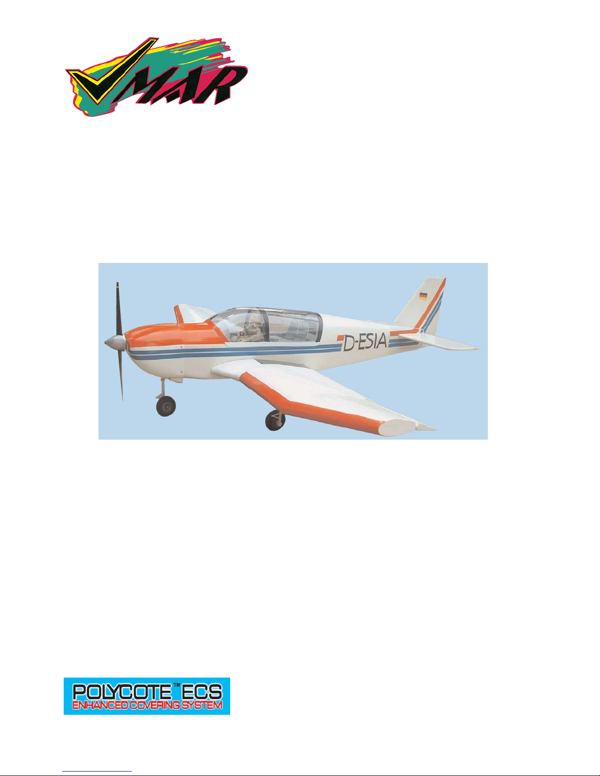
JODEL DR400 - 180
REGENT
ARF
SEMI SCALE MODEL
WITH POLYCOTE TMECS
ENHANCED GRAPHICS SYSTEM
Page 2
Stage 1
2
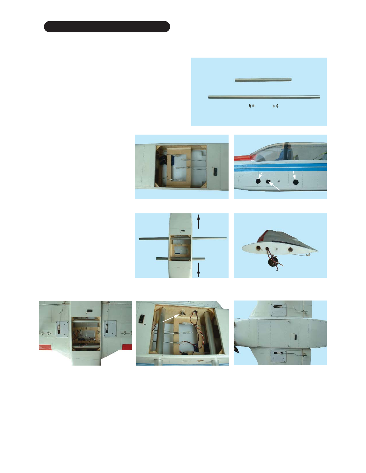
INSTALLING THE PLUG-IN WING
To install the plug-in wing to the fuselage you will need the
following parts.
- 2 aluminum tube spar joiners 2/3 inch (16mm) diameter
- 2 aluminum collars (see wing roots)
- 2 steel butterfly nuts (4mm) (see wing roots)
Step 1. Remove the hatch cover from
the bottom of the fuselage by
removing the retaining screws
and sliding the hatch slightly aft.
Step 2. Insert the front wing spar
joiner and then the rear spar joiner (see picture 1.2 & 1.3)
Step 3. Remove the nut and aluminum collar from the wing root
stud bolts. (see picture 1.4)
Step 4. Carefully insert the 2 wing
spar joiner tubes into the left
wing. (see picture 1.5)
Step 5.
Carefully mount the right
wing on to the spar joiner tubes.
(see picture 1.6)
Step 6. Secure the wings with
the collars & butterfly nuts.
(see picture 1.7)
1.1 Removed hatch cover
1.2 Wing spar joiner location
1.3 Install wing spar joiner
tubes into the fuselage
1.4 Wing root with stud bolt.
1.5 Left wing fitted.
1.6 Left & right wing fitted. 1.7 Wings secured in place.
Spar joiner location
Aileron servo wire exit hole
Wing bolt
Tail
Nose
Page 3
Stage 2
Stage 3
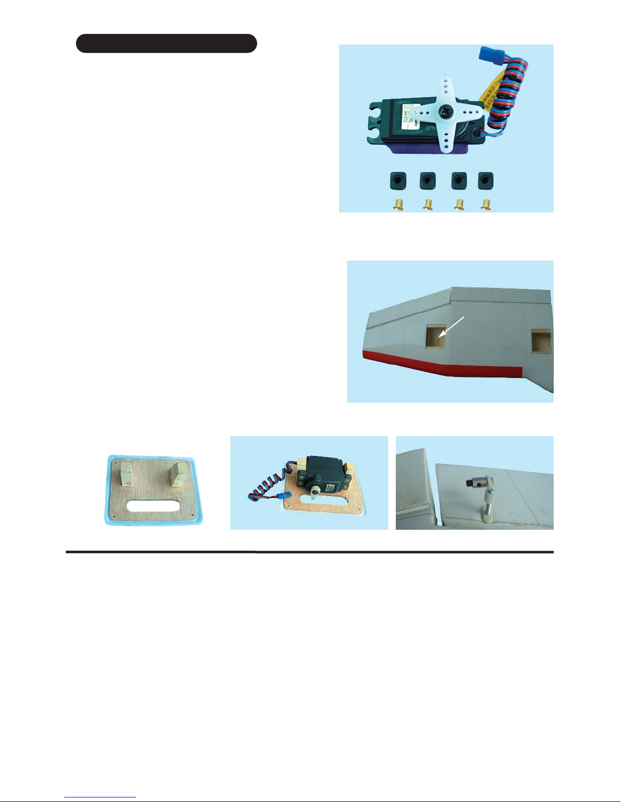
To install the aileron servos into the wing you will need the
following items :
- Servo
- Servo mounting screws and grommets as supplied with
servos.
- Servo control arms as supplied with the servos.
- Two aileron control rod assemblies supplied with the kit.
The assemblies consist of a metal rod with a plastic clevis
screwed on to one end .
- Low tack masking tape.
- 2 aileron control horn assemblies
2.1 Prepare the servos by fitting the rubber
grommets & ferrules supplied with your radio
FITTING AILERON SERVOS
Carefully remove the white cover plates from the aileron
servo cavities. Ensure you know which cover plate is for the
right wing and which is for the left. Remove the white cover
plates and retain the mounting screws. Notice that there are
wooden servo rails pre-installed into each servo cavity end.
Locate the wiring harness tubes that are protruding slightly
into each aileron servo cavity. The tube can be moved slightly at this point. Check out the other end of each tube for a
clean position and then using C/A glue secure the wiring harness tubes at the aileron servo cavity.
Install a servo in each aileron servo cavity and connect the
servo wire to the servo extension wires and run the extension
wires through wiring harness tubes to the centre of the wing
Install the aileron control horns.
2.2 Aileron servo location
2.4 Screw servo in position
2.3 Aileron servo mount 2.5 Install aileron control horn
Step 1 Consult your radio instruction manual and center each aileron servo by plugging it into the aileron chan-
nel in the receiver. Turn on the transmitter and then the receiver. Center the aileron trim lever on the transmitter.
Remove the servo arm mounting screw and the servo arm.
Step 2 Mount the servo arm back on the servo. Position the arm so that the arm is perpendicular to the surface of
the wing. Screw the arm into place with the servo arm mounting screw supplied with the servo.
Locate the two aileron control rods in the hardware bag. Ensure the clevise is well screwed on to the threaded
portion of the rod. Rotate and tug aggressively on the clevis and ensure that they are not loose on the rods.
Tape the ailerons into their neutral position so that they are even with the trailing edge of the wing and not pointing
either up or down.
Step 3 Ensure that the aileron control horns are screwed on to the threaded aileron control horn bolts and that both
control horns are in approximately the same place on their respective bolts.
Aileron servo cavity
Page 4
Stage 4
4
Step 4 Connect the clevis on each rod to their respective servo ouput arm.
metal pin or screw, attach that clevis to the servo output arm.
Step 5 Connect the other end of each aileron servo rod to the aileron control horn using the EZ connector.
Step 6 Remove the masking tape holding the ailerons.
Step 7 In the case of computer radios, couple the servos together by connecting them to the appropriate receiver
channel . In the case of analog radios couple the servos together using a Y harness.
Step 8 Turn on your radio and activate the ailerons, using the aileron stick and ensure that a smooth full motion
can be achieved.
Step 9 With the wing top side up and viewed from the back, ensure that moving the transmitter aileron stick to the
left raises the left aileron and lowers the right aileron. Movement of the stick to the left will roll the aircraft to the left.
(Counterclockwise roll of the wing when viewed from the back ).
Step 10 With the wing top side up and viewed from the back, ensure that moving the transmitter aileron stick to the
right raises the right aileron and lowers the left aileron. Movement of the stick to the right will roll the aircraft to the
right.
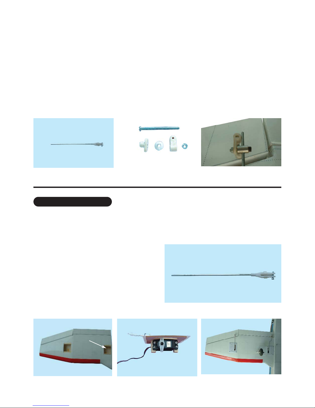
3.1 Aileron control rod assembly 3.2 Aileron control horn assembly 3.3 Aileron control installed
FITTING FLAP SERVOS
To install the flap servos into the wings you will need
the following items :
- Servos
- Servo mounting screws and grommets as supplied
with the servo.
- Servo control arm as supplied with the servo.
- Flap control rod assemblies
- Low tack masking tape.
4.1 Flap control rod assemblies
4.3 Flap servo in position 4.4 Final flap installation
Flap servo location
4.2 Flap servo in each wing
Page 5
Stage 5
Stage 6
5
4.5 Flap up (neutral position)
4.6 Flap down
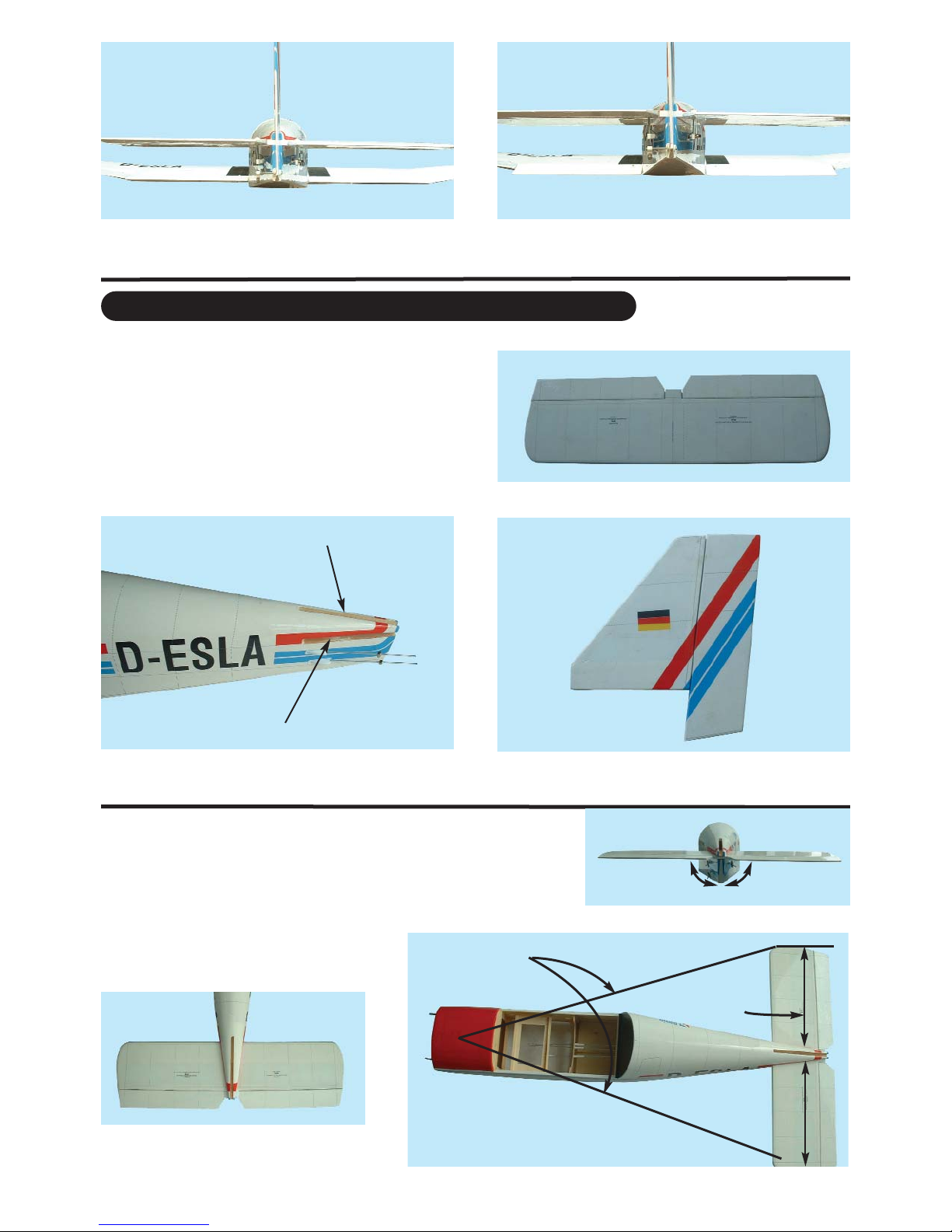
FITTING THE HORIZONTAL AND VERTICAL STABILIZER
To install the stabilizers to the fuselage you will need.
- Fuselage
- Vertical stabilizer with pre-installed rudder
- Horizontal stabilizer with pre-installed elevator
5.2 Factory machined stablizer slots.
Vertical slot
Horizontal slot
5.1 Horizontal stabilizer with pre-installed elevator
5.3 Vertical stabilizer with pre-installed rudder
Check the fit of the horizontal stabilizer
in its slot. Make sure the tail is square
and centred to the fuselage by taking
measurements as shown in the diagrams on the right, but don’t glue anything yet.
Equal
distance
Equal distance
6.1 Trial fit the horizontal stabilizer in
its slot
90
0
Page 6

6
Stage 7
With the horizontal stabilizer correctly aligned, mark the shape of the
fuselage on the top and bottom of
the tailplane using a water soluble non-permanent felt-tip pen as
shown here.
7.1 Mark the top and bottom of
the horizontal stabilizer
Stage 8
Now remove the horizontal stabiliz-
er and, using a sharp knife and a
ruler CAREFULLY cut 2mm inside
the marked lines and remove the
covering on the top and bottom of
the tail as shown. Make sure you
only cut the film and not the
wood, otherwise the horizontal sta-
bilizer will be severely weakened.
8.1 Marked lines on horizontal
stab
8.2 Cutting inside the lines
8.3 Remove covering from top
surface
8.4 Remove covering from bottom surface 8.5 Clean off any traces of pen
Now apply sufifciant epoxy to the top and bottom of the
horizontal stabilizer. Use 30 minute epoxy to ensure a
strong bond and give yourself plenty of working time.
Insert the horizontal stabilizer in its slot in the fuselage
and re-check the alignment as in Stage 9. Excess epoxy
should be cleaned off with a rag or tissue before it cures.
9.1 Apply plenty of epoxy 9.2 Slide the horizontal stabilizer
into place
9.3 Wipe off excess epoxy
Stage 9
Page 7

7
Check the fit of the vertical stabilizer in its slot.
Make sure that it is at a right angle to the horizontal stabilizer and fuselage
FITTING THE VERTICAL STABILIZER WITH RUDDER
10.1 Trial fit the vertical stabilizer into the fuselage slot.
Stage 10
11.1 Mark both sides of the vertical stabilizer
11.2 Carefully cut through the
covering
11.3 Remove covering from both
sides
Mark the shape of the fuselage on the left and right
sides of the vertical stabilizer using a felt-tip pen. Now
remove the vertical stabilizer and, using a sharp knife
& ruler, CAREFULLY cut 2mm inside
the marked lines and remove the covering on both
sides of the fin, just as you did with the horizontal stabilizer, making sure you only press hard enough to cut
the covering, not the wood of the vertical stabilizer.
Stage 11
Now apply plenty of epoxy to both sides and the bottom
of the vertical stabilizer. Use 30 minute epoxy to ensure
a strong bond and give yourself plenty of working time.
Insert the vertical stabilizer in its slot in the fuselage
and re-check the alignment. Excess adhesive should
be cleaned off with a rag or tissue before it cures.
12.1 Apply plenty of epoxy 12.2 Slide the fin into place 12.3 Insert the pre-installed hinge
to connect the rudder to the fuselage.
Stage 12
Page 8

Stage 13
Stage 14
Stage 15
8
Fit the nose gear steering arm
on to the EZ connector on the
steering arm pushrod as a per
illustration 14.1. Note which way
round the arm should be oriented.
Now slide the steering arm
into the middle of the pre-fitted
nylon nose gear bearing.
14.1 Insert the EZ connector
threaded shaft through the steering arm, secure with a nut and
place the arm into the nylon nose
gear bearing
14.2 Nose gear with wheel
14.3 Holding the nose gear steering arm in place, slide the
nosegear into the nylon mount,
passing through the steering arm.
14.5 Loosen the EZ connector
bolt to adjust the movement of the
nose gear control rod.
14.4 Now tighten the nosegear
steering arm set screw.
FITTING THE NOSE GEAR
Nose gear parts
Nose gear
with strut
Wheel collar
Steering arm
75 mm
wheel
FITTING THE MAIN LANDING GEAR
To install the landing gear, you will need:
- 2 main landing gear assemblies with struts
- 2 main wheels (60mm x 20mm)
- 2 wheel collars
- 4 landing gear straps (with 8 mounting screws)
15.1 Main landing gear components
Page 9

Stage 16
Stage 17
9
To assemble the fuel tank you will need the following
items:
- The fuel tank and fuel stopper assembly (supplied)
- The clunk (supplied)
- About 7” (20 cm) of medium ID silicone fuel line (DUB
197 or similar)
- Cross head Phillips screw driver
16.1 Use 100 mm (4 in) for fuel line
and 50 mm (2 in) for pressure line
16.2 Illustration of fuel line positioning inside the tank
16.3 Fuel tank test fitted on to
the dowels & power module.
100 mm (4 in) for fuel line
50 mm (2 in) for pressure line
pressure line
fuel line
pressure line
FITTING THE FUEL TANK
The engine and the fuel tank are installed onto the
power module. Remove the power module from
the fuselage by removing the 4 nuts & washer
17.1 Power module
15.3 Main landing gear esembly
15.2 Main landing gear location
15.4 Main landing gear in place 15.5 Main landing gear with
landing gear straps in place
Step 1. Turn over the wing to locate
the pre-drilled main landing gear
mounting holes (picture 15.2)
Step 2. Assemble
the main landing
gear as shown in picture 15.3
Step 3. Attach each landing gear
using 2 landing gear straps and
4 screws (picture 15.4 - 15.5)
Step 6. Tighten the screws
Step 5. Repeat this procedure
to install the landing gear
to the other wing half.
Pre-drilled landing gear
mounting holes
INSTALLING THE ENGINE
Page 10

Stage 18
10
17.9 Pitts type muffler suitable
for VMAX .46 and .52
17.8 Fuel line and pressure line
hook up to the engine
17.10 Fuselage without power
module
Fuel line
Pressure line
Pressure line
power module mount bolts
17.11 Power module mounted to
the fuselage
17.12 Power module mounted to
the fuselage (side view)
17.13 Cowl installation
FITTING ELEVATOR AND RUDDER CONTROL HORN
The elevator control horn is
fitted on the underside of
both right and left of the elevator halves. Pierce the covering over the pre-drilled
hole for the control horns
installation as shown.
18.1 Control horn assembly 18.2 Elevator control horn positions
17.4 VMAX .46 or .52 2 cycle engine
recommended
fuel tank
mounting dowels
17.6 Engine and fuel tank in position on the power module
17.5 Fitting the engine to the
engine mount
17.7 Engine and engine mount
recommended orientation
17.3 Aluminum engine mounts17.2 Power module assembly
Page 11

Stage 19
Stage 20
11
19.2 Note the orientation and positions of the
three servos in the servo tray
Throttle servo
Elevator servo
Rudder servo
19.3 Throttle, elevator and rudder servos connected to their pushrods
20.1 Consult the picture showing how the throttle, rudder,
nose gear steering and elevator servos are positioned
and connected to the pushrods.
CONNECTING THE PUSHRODS TO THE THROTTLE, RUDDER AND ELEVATOR SERVOS
INSTALLING THE SERVOS
Install the rubber servo grommets and brass ferrules supplied with your radio
equipment. The three servos that control the elevator, rudder and throttle are
Installed in the servo tray mounted in the fuselage. Remove the servo tray
from the fuselage. Mount the servos to the servo tray as shown.
19.1 Universal servo mount
18.3 Rudder control horn location
18.4 Elevator and rudder control horn connected to the control rod with EZ connector.
Page 12

Stage 21
Stage 22
Stage 23
12
CONNECTING THE THROTTLE CONTROL
Connect the clevis to the engine throttle arm at roughly half throttle. Look
into the throat of the engine carburettor as you rotate the throttle arm and
select a position where the throttle opening is about half what it is when
fully open.
23.1 Throttle control rod
Connected to the engine throttle arm
engine
throttle
arm
23.2 Throttle control rod connected to the engine throttle arm
CONNECTING THE PUSHRODS TO THE RUDDER
Connect the rudder servo to the
receiver and turn on your transmitter. Confirm that the neutral positions of the rudder servo are sustained as per illustration 20.4
22.1 Rudder control horn installed
and shown in neutral position
22.2 Connecting the rudder
pushrod to the rudder control
horn
Connect the elevator servo to the receiver and turn on your transmitter. Confirm that the
neutral position of the elevator servo is sustained as per picture 20.4
21.1 Pre-installed elevator
pushrod with elevator at neutral
21.2 Connecting the elevator
pushrods to the control horn
21.3
Connecting the elevator
pushrod to elevator control horn.
CONNECTING THE PUSHRODS TO THE ELEVATOR
20.2 Pre-installed elevator and
rudder and nose gear pushrods
20.3 Install clevises to the
servo arms
20.4 Connecting the elevator
pushrods to the elevator servo
Page 13

Stage 24
13
FINAL R/C SET-UP
Before starting the final
set-up of the model,
switch on the radio and
ensure that all trims are
in their neutral positions. Check that the
ailerons, elevator and
rudder are centered. If any
adjustments are needed, do these by uncoupling the relevant clevis
and turning it clockwise
to shorten the linkage
or counter - clockwise
to lengthen it. Only
when each control surface has been centered
mechanically in this
way should you begin
adjusting the surface
movement (or throw)
Now confirm
that the control surfaces
are moving
in the correct
direction.
Use the
servo reversing switches
on your
transmitter to
reverse the
direction of a
servo if necessary. The
most popular
transmitter
mode (with
the throttle
on the left,
with the
ailerons and
elevator on
the right) is
shown here.
Stage 25
ELEVATOR
UP
ELEVATOR
DOWN
AILERON
UP
AILERON
DOWN
AILERON
DOWN
AILERON
UP
RUDDER
RIGHT
RUDDER
LEFT
Adjust the deflection of the control surfaces to match the control surface throw specifications on page 15
You can reduce the amount of throw by doing either or both of the following:
From the servo end, move the clevis or EZ connector to a hole in the servo arm that is closer to the servo output
shaft.
From the control horn end, move the horn out further on the threaded bolts. Always confirm that the horn is still
thoroughly engaged with the threaded bolt after you have adjusted it.
ADJUST CONTROL SURFACE THROW LIMITS.
Stage 26
Page 14

27.1 Consult your radio manual for instructions
about hooking up your receiver battery, receiver and switch harness.
27.2 Wrap the battery pack securely in foam suitable for RC equipment and wrap the foam insulated pack in a plastic bag or cling wrap. Install the battery pack beneath the fuel tank.
27.3 Thread the battery pack connector back through from beneath the fuel tank to the radio compartment by passing the battery connector through an opening beside or beneath the fuel tank.
27.4 Connect the battery connector to your radio system according to the radio manual.
28.1 Consult your radio manual for instructions about hooking up your receiver.
28.2 Plan where you are going to put the receiver with consideration for routing the antenna safely.
28.3 Wrap the receiver securely in foam suitable for RC equipment and wrap the foam insulated receiver in a plas-
tic bag or cling wrap.
28.4 Generally in the absence of specific instructions from the radio manufacturer, it is recommended that the
receiver should be placed where it is least likely to have impact during a crash. Keep the battery pack and other
heavy loose items ahead of the receiver.
29.1 Consult your radio manual for instructions about testing and operating your radio system.
29.2 Pay particular attention to charging your radio system batteries and range testing the system before and after
each flight.
29.3 Check that all controls are working correctly before and after each flight.
The CG for your JODEL 400 should be located at 75 to 80 mm (3 to 3-1/4 inch ) back from the leading edge of the wing
when the wing has been attached to the fuselage.
For the initial flight, the CG should be located at 3 inches (75mm) back from the leading edge of the wing when
the wing has been attached to the fuselage.
The CG should be measured with the engine, radio gear and all other components installed but WITH NO FUEL IN THE
TANK.
Set up the CG as it will be when you fly it BUT WITH NO FUEL IN THE TANK.
It is very important to have the CG correct. Flying your model with the CG too far aft will likely lead to loss control and
a crash.
If you discover that after you have assembled your model and installed your radio and engine that the CG is incorrect you must bring the CG to the correct location by doing the following BEFORE FLYING :
- Move the battery pack fore or aft.
- Move other components fore or aft.
- Change engine to a lighter or heavier model.
- Add weight to the nose or tail. If adding it to the nose, try to make it useful by going to a heavier duty engine
or adding a spinner with a heavy metal backing plate. As a last resort, add stick on “dead” weight where appropriate.
14
Stage 28
INSTALLING THE RECEIVER
Stage 29
CONFIRM RADIO OPERATION
Stage 30
BALANCING THE AIRCRAFT.
INSTALLING THE RECEIVER BATTERY
Stage 27
Page 15

Parts for this VMAR Model
In the event that you require replacement parts for you VMAR PIPER TOMAHAWK you can order parts from
your retailer or from the VMAR On - line store at www
.richmondrc.com.
Please see the IMPORTANT INFORMATION sheet for parts for this model.
Wing set # Va.112L.046XW (a set of left and right with joiner etc)
Tail set # Va.112L.046XT (contains horizontal and vertical stabilizers)
Cowl # Va.112L.046XL (fiberglass)
Canopy set # Va.112L.046XN (canopy and frame)
Main gear # Va.112L.046XMG (fiberglass main landing gear with axle set)
Wheel pant set # Va.112L.046XWP (with main gear fairing set)
Covering set # Va.112L.046XV (POLYCOTE ECS)
Wing parts bag # Va.112L.046XWPB (spar joiner, aileron rods ect)
Master bag # Va.112L.046XMB (as in kit)
For aftermarket parts and other information related to this model see VMAR On - line at
www
.richmondrc.com.
15
80 mm
3 1/16 “
Elevator
Aileron
Rudder
5/8-1”
15-25mm
5/8-1”
15-25mm
1/4-3/8”
6-9mm
1/4-3/8”
6-9mm
1/3-1/2”
8-12mm
1/3-1/2”
8-12mm
CG
CONTROL SURFACE THROW SPECIFICATIONS : The throws are measured at the widest part of the control surface.
Adjust the position of the pushrods at the control/servo horns to control the amount of throw. You may also use the ATV’s
if your radio has them but the mechanical linkages should still be set so that the ATV’s are near 100% for best servo resolution.
Stage 31
CONFIRM MECHANICAL INTEGRITY
31.1 Once you have confirmed that the CG is cor-
rect, you should do a thorough review of the entire
model before your first flight. Check everything
twice! Every hook up, every coupling, everything!
Do it twice!!
31.2 Before your first flight, have an experienced
flyer review your work. Do not fly your model until it
has been checked out by a third party who knows
how to fly and how to set up a model aircraft
31.3 Once you have completed your first flight, get
in the habit of checking your model over before and
after each flight! Don’t fly if you find something that
is not right!
Low rate High rate
ELEVATOR 1/3“ (8mm) up 1/2” (12mm) up
1/3“ (8mm) down 1/2” (12mm) down
RUDDER 5/8" (15mm) right 1” (25mm) right
5/8" (15mm) left 1” (25mm) left
AILERON 1/4” (6mm) up 3/8” (9mm) up
1/4” (6mm) down 3/8” (9mm) down.
Page 16

16
POLYCOTE ECS
is a proprietary Enhanced Covering System engineered in Canada and available only from VMAR.
With POLYCOTE ECS the graphics are inside the covering... not stuck on top. No Decals! No Layers! No Strips!
No Stripes! POLYCOTE ECS utilizes ULTRA TOUGH polyester and our SURE SEAL system to ensure that the
seams stay down! Best of all POLYCOTE is totally fuel proof! Quite simply...
POLYCOTE ECS leads the pack in ARF covering systems!
CARE & CLEANING OF POLYCOTE ECS.
CARE: Avoid leaving your model in a closed car exposed to direct heating from the sun for lengthy periods.
Temperatures under such conditions can exceed 50C (122F) and sagging may occur.
TIGHTENING: To tighten POLYCOTE ECS we recommend using a hobby heat gun set for medium heat and a soft
cloth. We do NOT recommend an iron. Practice on the bottom of a less noticeable section first. On open bays, heat
and then let cool. On solid surfaces, heat and then lock down by rubbing.
RESEALING SEAMS: POLYCOTE ECS seams are sealed with our SURE SEAL system and will not normally lift.
If you find a loose edge, clean any oil residue from the area and reseal with thin CA.
PATCHING: If you should puncture POLYCOTE ECS, clean any oil residue from the area of the paper. Patch with
low temperature covering using a heat gun and soft cloth. See Tightening tips above.
CLEANING: To clean POLYCOTE ECS we recommend Fantastic household cleaner and disposable paper towels.
You can use just about any cleaner and we are not aware of any cleaner that will damage POLYCOTE but it is a
good idea to always test a small out of the way spot first. Wipe along seams, not across.
VMAR, POLYCOTE and VMAX are Trademarks of VMAR Manufacturing and appointed VMAR agents worldwide
Copyright VMAR Manufacturing and Richmond RC Supply Ltd 2003 # VMA-R160XIB
www.richmondrc.com
This model is covered with our ULTRA TOUGH POLYCOTE
ECS Enhanced Covering System.
TM
 Loading...