

Vmar J3.PIPER GUB, L4-GRASSHOPPER Assembly & Operation Manual
ALMOST
READY
TO FLY MODEL
J3.PIPER
GUB
L4-GRASSHOPPER
ASSEMBLY
& OPERATIONS
MANUAL
Please review
this
manual
thoroughly
before assembling or
operating this model.
Proceeding with
assembly
and use of this
product
indicates
A Remote
Gontrol Model Aircraft is not
a
toy.
lt is
a flying
model
that functions
much like
a
full
size
airplane. lf
you
do not
assemble
and operate this
product properly
you
can cause injury
to
yourself
and others and
damage
prop-
erty. DO
NOT FLY this model
if
you
are not
qualified.
You
are entirely responsible
for
the mechanical,
aeronautical and electrical integrity
of this model
and it's
structure,
control
surfaces, hinges, linkages,
covering,
engine, radio, wiring,
battery
and all other
components.
Gheck all components
before and after
each flight.
Don't
fly until it's
right!
POLYCOTE*EGS
ENHANCED
COVERING
SYSTEM
w
Agreement With
&
Acceptance
of the
following
Liability Disclaimer.
Model
airplanes, model
engines, model
engine
fuel,
propellers
and
related
accessories,
tools and equipment
can be haz-
ardous if improperly
used. Be cautious
and
follow
all
safety
recommendations
when using
your
VMAR
model
airplane.
Keep hands,
tools, clothing
and all
foreign
objects well
clear of
engines when
they are
operating.
Take
particular
care to safe-
guard
and
protect
your
eyes and
fingers
and the
eyes and
fin-
gers
of other
persons
who
may be nearby.
Use only a
good
quality propeller
that has no
cracks or flaws.
Stay clear of the
propeller
and
stay clear of the
plane
of rotation defined
by
the
propeller.
The Manufacturer,
Distributor,
Retailer and/or
other
suppliers of this
product
expressly
disclaim any warranties
or
representations,
either expressed or implied,
including
but
not
limited
to implied warranties
of
fitness
for the
purposes
of
achieving and sustaining remotely
controlled flight. ln no
event
will the Manufacturer, Distributor,
Retailer
and/or other suppli-
ers of this
product
have any obligation
arising from
contract or
toft, or for loss
of
revenue
or
profit,
or for indirect,
special, inci-
dental, consequential
or other damages
arising
from
the use
of
this
product.
ln
purchasing
and/or
using this
product,
the
user
accepts
all
responsibility
for its use
and accepts all liability
associated with such use.
The
Graphics
and Detailing
are
inside
the POLYCOTE ECS/
WING ASSEMBLY
Parts
needed
-
Roll of
wing
joiner
tape
-
Right and
left wing
panels
-
Wing
joiner
(also
called dihedral
brace)
Step
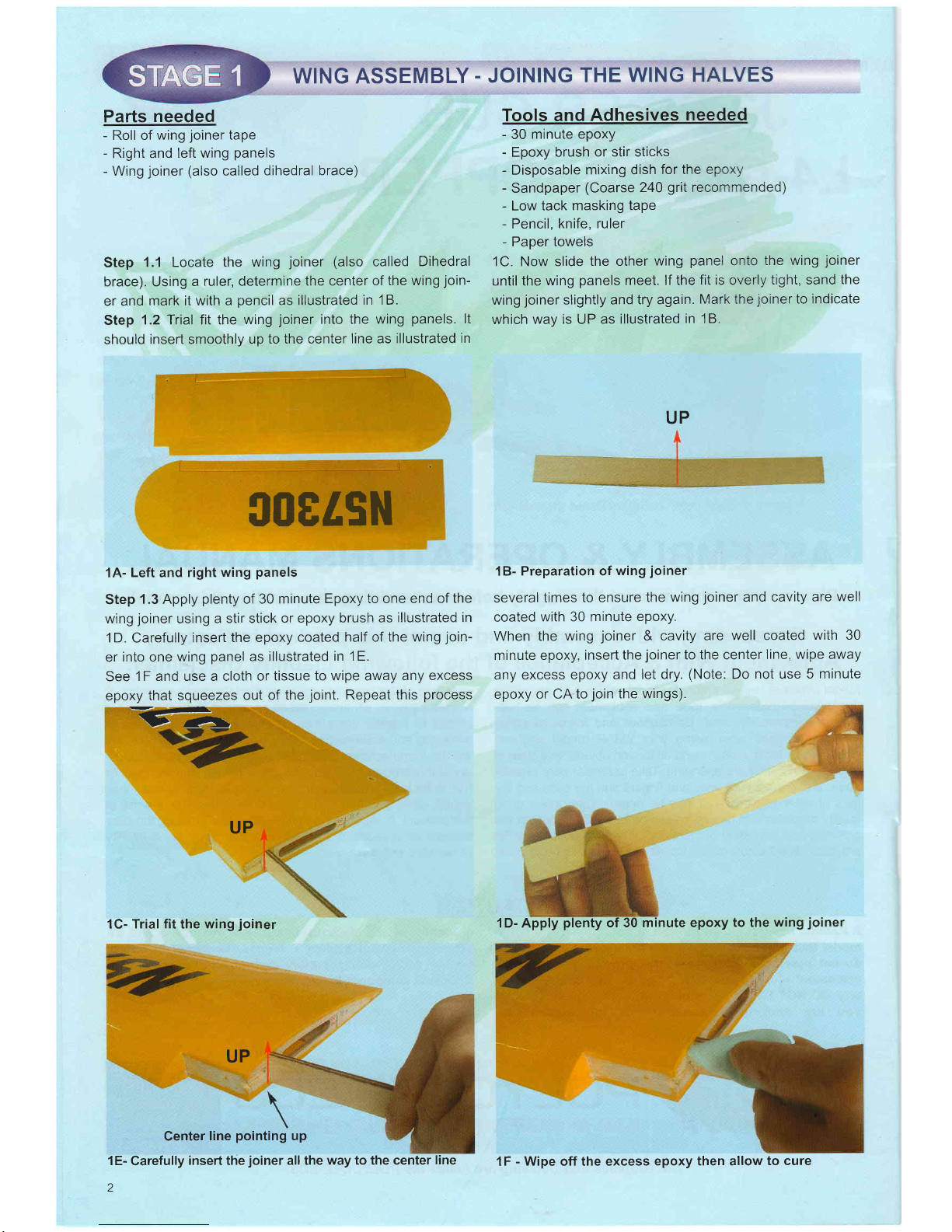
1.1 Locate
the wing
joiner
(also
called
Dihedral
brace). Using
a
ruler, determine
the center
of the wing
join-
er and
mark it with a
pencil
as illustrated
in 1B.
Step
1.2 Trial fit the
wing
joiner
into the
wing
panels.
lt
should
insert
smoothly
up
to the center
line as
illustrated
in
SIIETSN
1A-
Left
and
right
wing
panels
Step
1.3 Apply
plenty
of 30
minute
Epoxy to one end
of the
wing
joiner
using
a stir stick
or epoxy
brush as
illustrated
in
1D.
Carefully
insert
the epoxy
coated
half
of
the wing
join-
er
into one
wing
panel
as
illustrated
in
'lE.
See
1F and use a cloth
or
tissue to wipe away
any excess
epoxy
that squeezes
out of
the
joint.
Repeat this
process
rL
UP
1C- Trial
fit
the
wing
joi
UP
Center
line
pointing
up
1E-
Carefully
insed the
joiner
all the
way to the center
line
2
.
JOINING
THE
WING HALVES
Tools and
Adhesives
needed
-
30
minute epoxy
-
Epoxy brush
or stir sticks
-
Disposable
mixing dish
for the epoxy
-
Sandpaper
(Coarse
240
grit
recommended)
-
Low tack
masking tape
-
Pencil,
knife, ruler
-
Paper
towels
1C. Now slide
the other
wing
panel
onto
the wing
joiner
until the
wing
panels
meet. lf the
fit is overly
tight, sand
the
wing
joiner
slightly and
try again.
Mark the
joiner
to
indicate
which
way is UP
as illustrated
in 18.
UP
1B-
Preparation of
wing
joiner
several
times
to ensure
the
wing
joiner
and cavity
are
well
coated
with 30 minute
epoxy.
When the
wing
joiner
& cavity
are
well coated
with 30
minute epoxy,
inserl the
joiner
to the center
line,
wipe away
any excess
epoxy
and let dry.
(Note:
Do
not
use
5
minute
epoxy
or CA to
join
the wings).
1D- Apply
plenty
of 30 minute epoxy
to the
wing
joiner
n
1F
-
Wipe off the excess
epoxy then allow
to cure
WING
ASSEMBLY - JOINING THE WING HALVES
(Gont.)
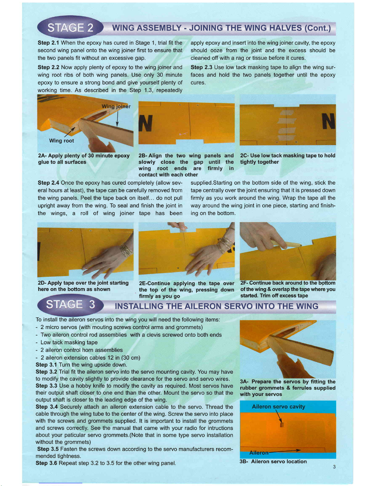
2A- Apply
plenty
of30 minuta epory 2B-Align the two wing
panels
and 2C- Use low tack masking tape to
hold
gluetoall
surfac6 slowly close the
gap
until the tightly together
:ilg",'iil
"11f"."31"
rirmr' in
Step 2.4 Once the epoxy has cured completely
(allow
sev- supplied.Starting on
the bottom side of the wing, stick the
eral
hours
at
least), the
tape can
be carefully removed from tape centrally over the
joint
ensuring that it is
pressed
down
the
wing
panels.
Peel the tape back on
itself...
do
not
pull
firmly
as
you
work around the wing. Wrap the tape all the
upright away from the wing.
To
seal and
finish
the
joint
in way
around
the wing
joint
in one
piece,
starting and finish-
the wings, a roll of wing
joiner
tape has been
ing
on the bottom.
Step
2.1
When the epoxy has cured in Stage 1, trial fit the
second wing
panel
onto the
wing
joiner
first
to ensure that
the two
panels
fit without
an excessive
gap.
Step
2.2 Now
apply
plenty
of epoxy to the wing
joiner
and
wing
root ribs of both wing
panels.
Use only
30
minute
epoxy
to
ensure a strong bond
and
give yourself plenty
of
working time. As described in the Step 1.3, repeatedly
apply epoxy
and
insert into the wing
joiner
cavity,
the
epoxy
should ooze
from
the
joint
and the excess should be
cleaned off
with
a
rag or tissue before it cures.
Step
2.3
Use
low tack maskilg tape to
align
the wing sur-
faces and hold the
two
panels
together until
the
epoxy
cures.
3A- Prepare the servos
by
fitting
the
rubber
grommets
&
ferrules
supplied
with
your
seryos
2D- Apply tape over the
joint
starting
here on the boftom as shown
To install
the aileron servos into the wing
you
will need
the
following
items:
-
2 micro
servos
(with
mouting
screws control arms
and
grommets)
-
Two
aileron control rod
assemblies
with
a clevis screwed onto both ends
-
Low
tack masking tape
-
2
aileron
control
horn assemblies
-
2 aileron
extension cables
12
in
(30
cm)
Step 3.1 Turn the wing upside down.
Step
3.2
Trial
fit the aileron servo into the
servo
mounting
cavity. You may have
to modify
the cavity
slightly to
provide
clearance
for
the
servo and servo wires.
Step
3.3 Use a hobby knife to modify the
cavity as
required.
Most servos have
their
output shaft closer to
one end than
the
other. Mount the servo so that the
output shaft is
closer to the leading edge of the wing.
Step 3.4 Securely attach an aileron
extension cable
to
the servo. Thread the
cable through the wing tube
to the center of the wing. Screw the servo into
place
with the
screws
and
grommets
supplied.
lt
is important to install the
grommets
and screws correctly. See the manual that
came
with
your
radio
for
intructions
about
your paticular
servo
grommets.(Note
that in some type
servo
installation
without
the
grommets)
Step 3.5 Fasten
the screws down according to the seryo manufacturers recom-
mended
tightness.
Step 3.6 Repeat step 3.2 to 3.5 for the other wing
panel.
2E-Continue applying the tape over
2F-
Gontinue
back around to the bgttom
the top of the wing,
pressing
down
of
the wing & overlap
the tape
where
you
firmly
as
you go
stafted.
Trim
off excess tape
INSTALLING THE AILERON
SERVO
INTO THE WING
38- Aileron servo location
INSTALLING
THE AILERON
CONTROL
SYSTEM
Step 4.1
Consult
your
radio instruction manual
and center
the
aileron
servos using either a Y connector
or a comput-
er
radio
that accomodates the use
of
two
aileron servos.
Turn on the
transmitter and then the receiver.
Center the
aileron trim
lever on the transmitter. Remove
the servo arm
mounting
screws and servo arms.
Step
4.2 Mount
the servo arms
back on the servos so that
the
seruo arms are
parallel
with the
back edge of the wing.
Screw the arms into
place
using the servo arm mounting
screws supplied with the servos.
Step
4.3
Locate the two aileron
control
rods in
the hard-
ware
bag
(see
4A). Ensure the
clevises are screwed well
onto the threaded
portion
of
the rod.
Rotate
and tug
aggressively
on
the
clevises and ensure that
they are not
loose
on the
rods.
Step 4,4Tape
the ailerons into
their
neutral
position
so that
they are
even with the trailing
edge of
the wing
and not
pointing
either up or down.
Step
4.5
Install the aileron control horns
as illustrated in 48
and ensure they align with the
servo arms.use 30 minute
epoxy .
dr*lfl**rd
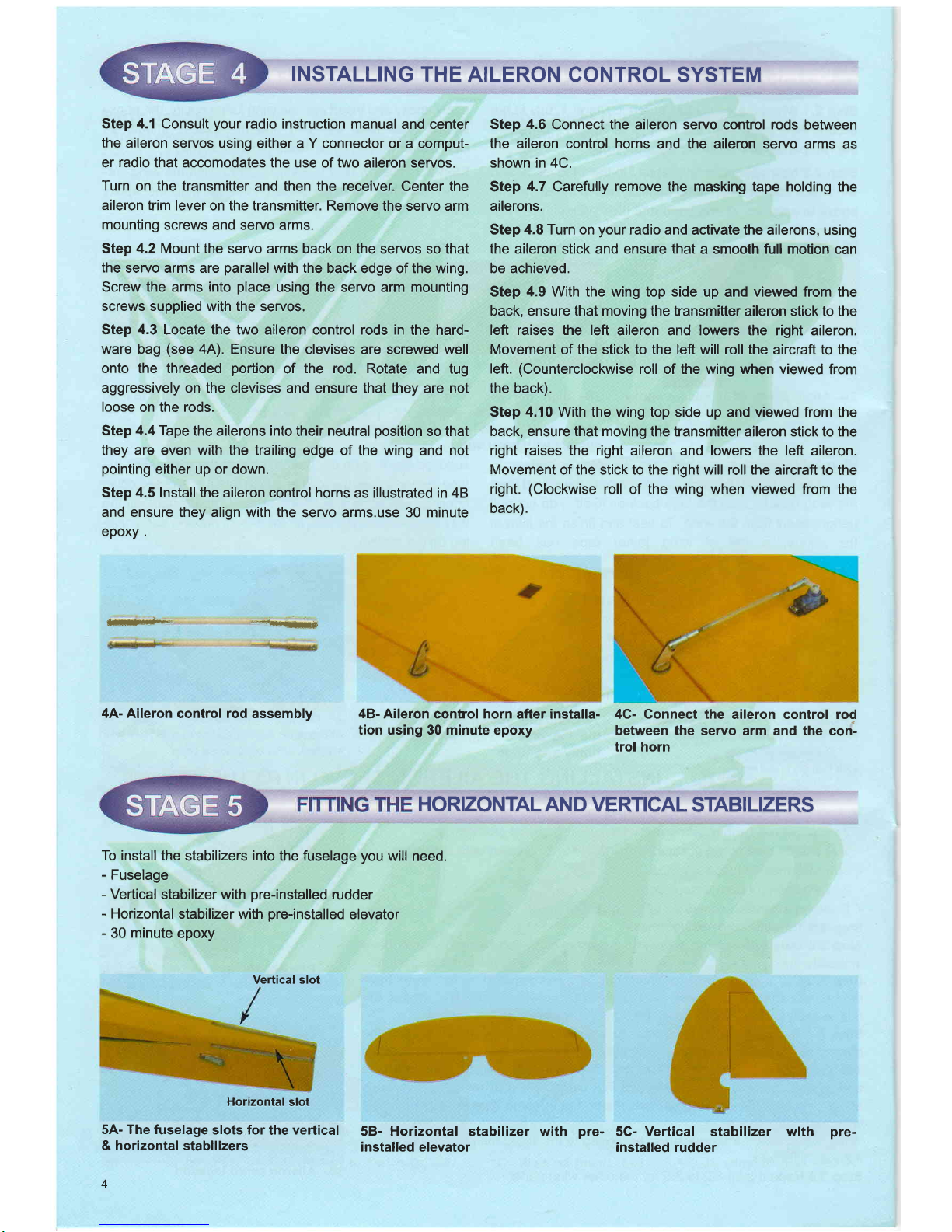
4A- Aileron
control
rod
assembly
Step 4.6
Connect the aileron servo
control
rods
between
the aileron control horns
and the aileron seryo
arms as
shown in 4C.
Step
4.7
Carefully remove the masking tape holding
the
ailerons.
Step 4,8 Turn on
your
radio and
activate the ailerons, using
the aileron
stick and
ensure that
a smooth full motion can
be achieved.
Step
4.9
With the wing top side up
and
viewed from the
back,
ensure that
moving
the transmitter aileron
stick
to the
left raises the left
aileron and lowers the right aileron.
Movement
of the stick to the left will roll the aircraft to the
left.
(Counterclockwise
roll of the wing when viewed
fr:om
the back).
Step 4.10 With the wing
top side up and viewed from the
back, ensure that moving
the transmitter aileron stick to the
right raises the right
aileron and lowers the left aileron.
Movement
of the stick to the right will roll the
aircraft to the
right.
(Clockwise
roll of the wing when viewed from
the
back).
48-
Aileron control horn
after installa-
tion using
30
minute
epoxy
4G- Connect the
aileron control rod
between
the servo arm and the con'-
trol horn
HORIZONTAL
AN D
VERTICAL
STABI
LIZERS
To
install the
stabilizers
into
the fuselage
you
will need.
-
Fuselage
-
Veftical
stabilizer with
pre-installed
rudder
-
Horizontal
stabilizer with
pre-installed
elevator
-
30
minute
epoxy
Horizontal
slot
5A- The fuselage
slots for
the
vertical
&
horizontal
stabilizers
4
58- Horizontal stabilizer with
installed elevator
pre-
5C- Vertical stabilizer
with
installed rudder
Vertical slot
pre-
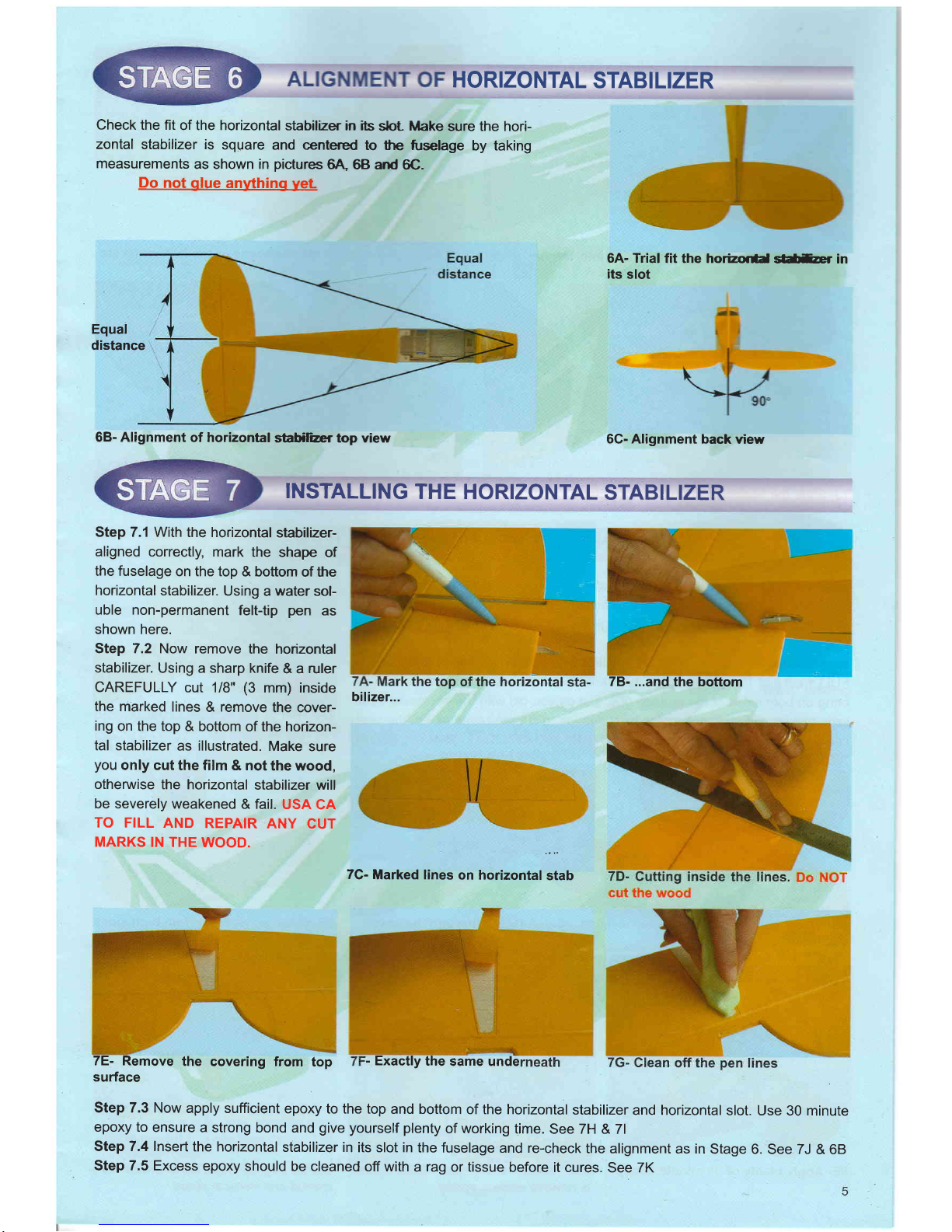
HORIZONTAL
STABILIZER
Check
the fit
of the horizontal
stabilZer in ibs
sbt Make
sure the hori-
zontal
stabilizer is
square
and centered
to the
fuselage
by taking
measurements
as shown in
pictures
6A,
68 and
6C.
Do
not
glue
anything
yet
6A- Trial
fit the horizor*d
sl*tur in
its
slot
Equal
distance
68- Alignment
of horizontal
stabiliar top view
6G- Alignment back
view
INSTALLING
THE HORIZONTAL
STABILIZER
Step 7.1 With
the horizontal
stabil2er-
aligned
correctly,
mark the
shape
of
the fuselage
on the top
& bottom
of the
horizontal
stabilizer.
Using
a
water
sol-
uble non-permanent
felt-tip
pen
as
shown here.
Step 7.2 Now
remove
the horizontal
stabilizer.
Using a sharp knife
& a ruler
CAREFULLY
cut 1/B'
(3
mm) inside
the marked
lines & remove
the cover-
ing
on the top
& bottom
of the horizon-
tal stabilizer
as illustrated.
Make
sure
you
only cut
the film & not
the wood,
otherwise
the horizontal
stabilizer will
be severely
weakened
& fail.
USA
CA
TO FILL
AND
REPAIR
ANY
CUT
MARKS
IN THE
WOOD.
7C-
Marked lines
on horizontal
stab
7E- Remove
the
covering from
top
surface
Step 7.3 Now
apply sufficient
epoxy to the top
and bottom of the horizontal
stabilizer
and horizontal
slot. Use 30 minute
epoxy to
ensure a strong
bond and
give
yourself plenty
of working
time. See ZH & 7l
Step 7.4 Insert
the horizontal
stabilizer in its slot in
the fuselage and re-check
the alignment
as in Stage
6. See 7J & 68
Step 7.5 Excess
epoxy should
be cleaned off with a rag
or tissue
before it cures. See 7K
78- ...and
the bottom
bilizer...
-
Exactly
the
same unde
 Loading...