

Page 1
FOURNIER
RF.4D
ASSEMBLY
&
OPERATIONS
MANUAL
Please
review this manual thoroughly before assembling or operating this
model.
Proceeding with
assembly and use of this
product
indicates
Agreement With
&
Acceptance of the
following Liability Disclaimer.
Model
airplanes,
model
engines, model engine fuel,
propellers
and related accessories, tools
and equipment can be haz-
ardous if improperly
used.
Be
cautious and
follow
all safety
recommendations
when using
your
VMAR model
airplane.
Keep hands, tools,
clothing and all
foreign
objects well clear of
engines when they are
operating.
Take
particular
care to
safeguard and
protect
your
eyes and
fingers
and the eyes
and
fingers
of other
persons
who
may be nearby. Use only a
good
quality propeller
that has no
cracks or flaws. Stay clear of the
propeller
and stay clear of the
plane
of rotation defined
by
the
propeller.
The
Manufacturer, Distributor, Retailer
andior other
suppliers of this
product
expressly disclaim any
warranties
or
representations, either expressed or
implied, including but not
limited to
implied warranties of fitness for the
purposes
of
achieving and sustaining
remotely controlled flight. ln no event
will the Manufacturer,
Distributor, Retailer
andior
other
suppliers of this
product
have any obligation arising
from
contract or tort, or for loss of revenue or
profit,
or
for indirect,
special, incidental, consequential or other damages arising
from the use of this
product.
In
purchasing
and/or using
this
product,
the
user accepts
all responsibility for its use
and
accepts all
liability
associated
with
such
use.
A
Remote Gontrol Model Aircraft is
not a toy..lt is
a
flying
model
that functions
much
like
a full
size
airplane. lf
you
do not assemble
and operate this
product properly
you
can cause injury
to
yourself
and others and
damage
property.
DO NOT
FLY this model if
you
are
not
qualified.
You
are entirely responsible for
the mechanical,
aeronautical and
electrical integrity of this model and
it's
structure, control surfaces,
hinges,
finkages,
covering,
engine, radio,
wiring,
battery and
all other
components.
Check all components
before and after each flight.
ENHANCED
COVERING SYSTEM
The
Graphics and
Detailing
are
inside
the
POLYCOTE ECS/
Page 2
Parts
needed
WING ASSEMBLY.
JOINING THE WING
HALVES
-
Right and left wing
panels
-
Roll
of
wing
joiner
tape
-
Wing
joiner
(also
called dihedral brace)
-
Two
short dowel
guides
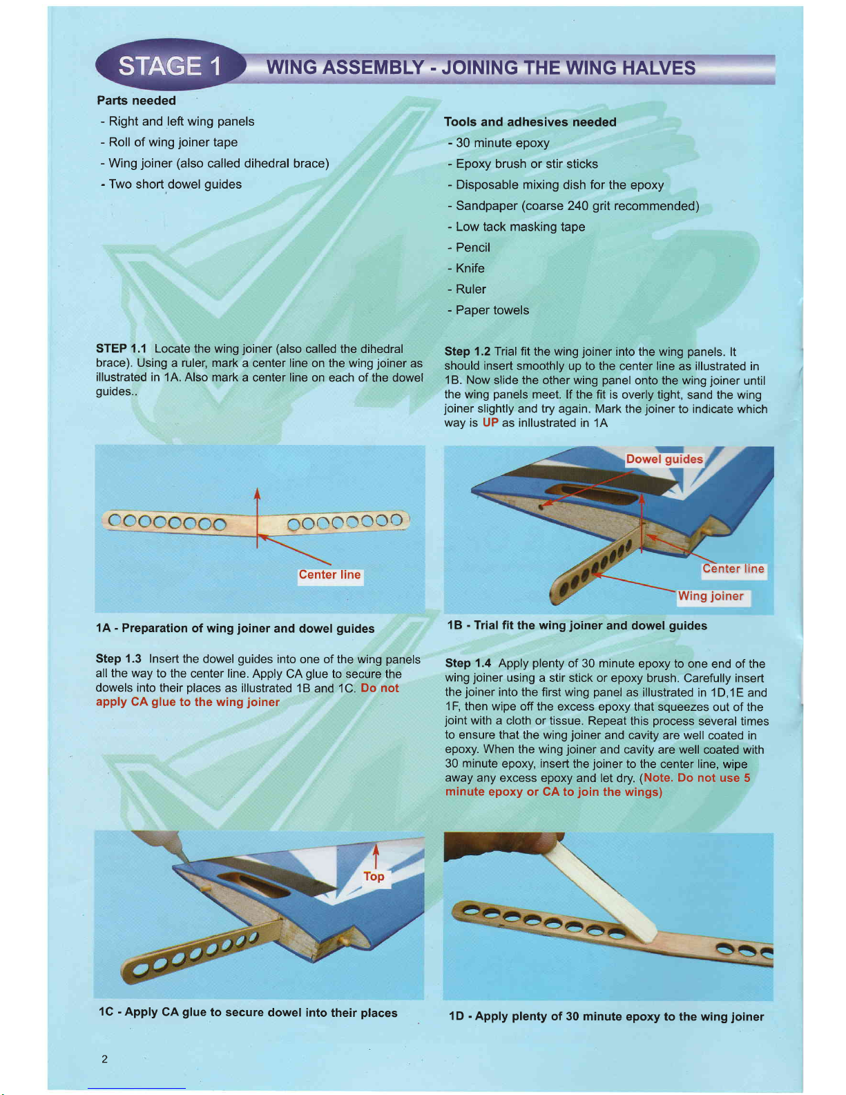
STEP 1.1 Locate
the wing
joiner
(also
called the dihedral
brace).
Using a ruler, mark
a center line on the wing
joiner
as
illustrated in
1A. Also mark
a center line on each of
the dowel
guides..
onooccc
1A
-
Preparation
of wing
joiner
and dowel
guides
Step
1.3
Insert the
dowel
guides
into
one of the wing
panels
all the way
to the
center line. Apply
CA
glue
to secure
the
dowels into
their
places
as
illustrated
1B
and 1C.
Do not
apply
CA
glue
to the wing
joiner
1G
-
Apply
CA
glue
to secure
dowel into
their
places
2
Tools
and adhesives needed
-
30 minute
epoxy
-
Epoxy
brush or stir sticks
-
Disposable mixing
dish for the
epoxy
-
Sandpaper
(coarse
240
grit
recommended)
-
Low tack masking
tape
-
Pencil
-
Knife
-
Ruler
-
Paper towels
Step 1 .2Trial fit
the wing
joiner
into the wing
panels.
lt
should insert smoothly
up to the center line
as
illustrated
in
1B. Now
slide the other wing
panel
onto the wing
joiner
until
the wing
panels
meet. lf the fit is overly
tight, sand the wing
joiner
slightly
and try again. Mark the
joiner
to indicate which
way
is
UP
as inllustrated
in 1A
1B
-
Trial fit
the
wing
joiner
and dowel
guides
Step
1.4
Apply
plenty
of 30 minute
epoxy to one
end of the
wing
joiner
using
a stir stick or
epoxy brush. Carefully insert
the
joiner
into the first wing
panel
as illustrated
in 1D,1E and
1F,
then wipe off the
excess epoxy
that squeezes
out of the
joint
with a cloth
or tissue. Repeat
this
process
several times
to ensure that
the wing
joiner
and cavity are well
coated in
epoxy.
When the wing
joiner
and cavity
are well
coated with
30 minute
epoxy, insert
the
joiner
to the
center
line,
wipe
away
any excess
epoxy and let
dry.
(Note.
Do not use
5
minute
epoxy
or GA to
join
the
wings)
Center line
Center line
Wing
joiner
1D
-
Apply
plenty
of 30 minute
epoxy to the wing
joiner
Page 3
Genter
line
pointing
up
1E-
Carefully
insert the
joiner
all
the way to
the
line
WING
ASSEMBLY
WING ASSEMBLY.
Step 2.1
When the epoxy
has cured in stage
1, trial fit
the second
wing
panel
onto the
wing
joiner
first to ensure
that the two
panels
fit without an
excessive
gap
Step 2.2
Now
apply
plenty
of epoxy
to the wing
joiner
and
wing roots
ribs
of
both wing
pannels.See
2A
Use
only 30
minute
epoxy
to ensure a strong
bond
and
give youself
plen
ty of working time
2A- Apply
plenty
of 30
minute epoxy
28
-
Align the wing
panels
and slowly
to all'surfaces close
the
gap
until
the
wing roots are
firmly in contact
with each other.
WING HALVES
(Gont.)
Step
2.3 As described
in Step
1.4, repeatedly apply
30
minute epoxy
to the wing
joiner
and insert
into the wing
joiner
cavity
Step
2.4 When the epoxy
has been
plentifully
applied,
align and
mate
the wing halves. See
28. Ensure the
wing
roots are
firmly in contact
with each other.
Clean off any
excess
epoxy seeping
from the
joint
before it cures.
Step 2.5 Use
low tack
masking tape to
hold the wing
pan-
els together
until the
epoxy cures.
See 2C
2G- Use
low
tack
masking tape
to
hold tightly
together
JOINING
THE WING
HALVES
(Cont.)
Step 3.1 When the epoxy has cured completely
(allow
several
hours at least), the tape can be
carefully removed from
the wing
panels.
Peel the tape back on
itself.... do not
pull
upright away
from the wing. To seal and
finish the
joint
in the
wings, a roll of wing
joiner
tape has been supplied.
Starting on the bottom side
of the wing, stick
the tape centrally over
the
joint
ensuring
that it is
pressed
down firmly as
you
work around the wing.
Wrap the tape all the way around
the wing
in one
piece,
starting
and finishing at the wiring harness cavities
at the top of tfle
wing
3A
-
Straddle the
wing
joint
tape over
the
wing
joint
starting
here on the
bottom of the wing.
38
-
Gontinue
around the
wing.
Ensure the tape straddles
the
joint.
3G-
Continue over the
top of the
wing
and trim off the
excess
tape
1F-Wipe
off the excess
epoxy then allow
to cure
Page 4
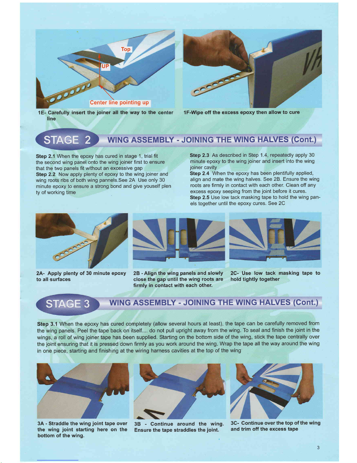
INSTALLING THE AILERON SERVOS
INTO THE WING
To install the aileron servos
into the wing
you
will need the
following items
-
Servos
-
Servo mounting screws
and
grommets
as supplied
with
the servos
-
Servo control arms as
supplied with the
radio
-
Two
aileron
control
rod
assemblies supplied
with the
kit.
-
Low tack masking tape
-
2 aileron control
horn
assemblies
Step
4.1frial fit the aileron seryo into the servo
mounting
cavity. You may have to modify
the
cavity
slightly to fit the
SCTVO
Step
4.2
Consult
your
radio
manual to fit the
grommets
and
ferrules correctly. Secure
the
servo
into
place
with the
SCTEWS.
4A- Prepare the servo by
fitting
the
rubber
grommets
&
ferrules supplied
with
your
radio
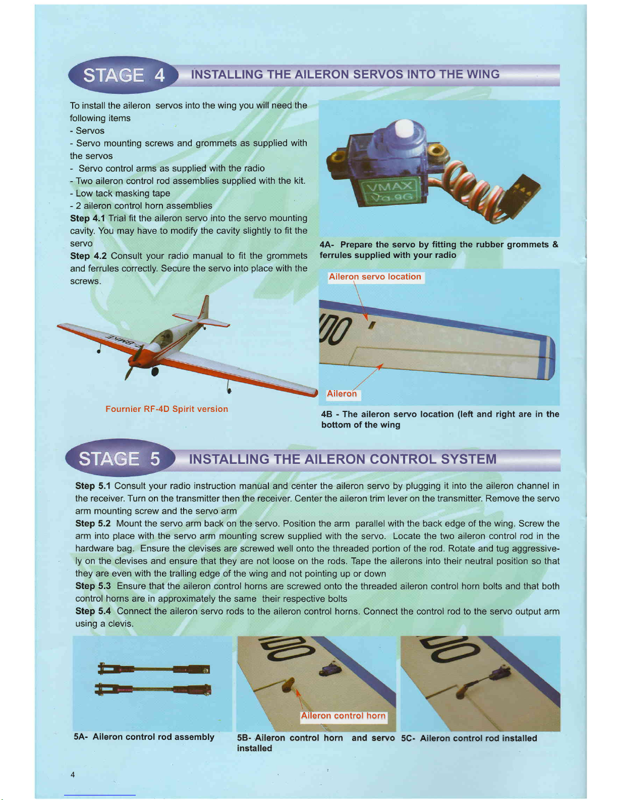
Aileron servo
location
Fournier RF-4D Spirit version
Aileron
48
-
The
aileron
servo location
(left
and right are in the
bottom of the
wing
INSTALLING
THE AILERON CONTROL SYSTEM
Step 5.1 Consult
your
radio instruction
manual and center the aileron servo by
plugging
it into
the aileron channel
in
the receiver. Turn
on the transmitter then the receiver. Center the aileron trim lever on the transmitter. Remove the servo
arm mounting screw and the servo
arm
Step 5,2 Mount the servo arm back on the servo. Position the arm
parallel
with the back edge of the wing. Screw the
arm into
place
with the servo
arm mounting screw supplied with the servo. Locate the two aileron control rod in the
hardware bag. Ensure the clevises are screwed well
onto
the threaded
portion
of the rod. Rotate
and tug
aggressive-
ly on the clevises and ensure that they are not loose on the rods. Tape the
ailerons
into their neutral
position
so
that
they
are even with the tralling edge of the wing and not
pointing
up or down
Step 5.3 Ensure
that the aileron control horns are screwed onto the threaded aileron control horn bolts and that both
control horns
are
in
approximately the same their respective bolts
Step 5.4 Connect the
aileron servo rods to the aileron control horns. Connect the control rod to the servo output arm
using a clevis.
5A- Aileron
control
rod
assembly
4
Aileron
control
horn
\.
\.
\1
\
58- Aileron control horn
and servo
installed
\
5C-
Aileron
control
rod installed
Page 5

Step
5.5 Connect the other end of the control rod to the control horn
using the second clevis
Step
5.6
Remove
the masking tape holding the aileron.
Step
5.7
In
the case of computer radios couple the servos together electronically by connecting them to the approriate
receiver channels. In the
case of analog radios couple the servos together using a Y harness.
Step 5.8 Turn on
your
radio and activate the ailerons, using the aileron
stick
and ensure a smooth full motion can be
achieved.
Step 5.9
With
the wing top side up and viewed from the back, ensure that moving the transmitter aileron stick to the lefi
raises the left
aileron and
lowers
the right aileron. Movement of the stick to the left will
roll
the aircraft
to the left.
(Counterclockwise
roll of the wing when viewed from the back).
Step 5.10 With the wing top side up and viewed from the back, ensure that moving the transmitter aileron stick to the right
raises the right aileron and lowers the Ieft aileron. Movement of the stick to the right will roll the aircraft to the right.
FITTING THE HORIZONTAL AND VERTICAL STABILIZERS
To install the
stabilizer
into the fuselage
you
will need:
-
Fuselage
-
Vertical
stabilizer with
pre-install
rudder
-
Horizontal
stabilizers with
pre-installed
elevators
Vertical stabilizer
slots
6A- The fuselage
slots
for
the
veftical
&
horizontal
stabilizer
!
ia.="'"
68- Vertical
stabilizer
with
pre-install
rudder
6G-Horizontal stabilizer
with
pre-
installed elevators
INSTALL THE HORIZONTAL
STABILIZER
Mount the wing onto the fuselage first. The wing will be used as a reference
point
to align the horizontal stabilizer.
7A- Trail fit
the
horizontal
stabiliz-
er into the fuselage.
7B' Before
gluing
anything, dry
(test)
fit the horizontal stabilizers
and ensure they align
parallel
to
the
wing
and at 90 degrees to the
fuselage.
7G- Apply sufficient 30 minute
epoxy
to the exposed wood on
both side of the
horizontal
stabiliz-
ers.
7D- Apply sufficient
30
minute
epoxy to the exposed wood
on
horizontal
slots
7E-
Slide horizontal stabilizer
into the slots
7F- Make
sure
the horizontal sta-
bilizers are align and
square
to the
fuselage
Horizontal stabilizer slots
the
Page 6

INSTALLING THE VERTICAL
STABILIZER
8A- Trial fit vertical
stabilizer into the
slot
in
the
of the fuselage.
88- confirm
the
vertical
stabilizer
is
at
90 degiees with respect
to the
hori-
zontal
stabilizer
8C-
Apply
sufficient 30
minute
epoxy
to the exposed wood in the vertical
stabilizer
8F- Before the epoxy cures, confirm
the both
vertical
stabilizer is at 90
degrees with respect
to the
horizontal
stabilizer
8D-
Apply
sufficient 30 minute epoxy
8E-
Insert
the top
vertical
siabilizer to
to the vertical
slot
the top vertical slot, clean
of the
excess epoxy
INSTALL
THE LANDING
GEAR
The
Fournier RF-4D has a main
gear
located
at the
fuselageclose
to the leading edge two console
gear
located at the wing and
the tail steering wheell
-
1 main landing
gear(with
pre-cut
main
gear
bearing and four 3 x 15mm bolts and nuts
)
-
2 Pre-bent
console
wing
gear
-
8 sheet metal screws
(2
x l0
mm)
-
4 Plastic landing
gear
straps
-
1
tail wheel assemblv
Bottom view
Ew--
-
\
Main
landing
gea
9A- Components
of one main
landing
gear
98- Fit main landing
location
9C- Using 4
(3
x 15 mm)
to mount
main landing
gear
to the fuselage
10C-
same as the left wing mount
the
wing console
gear
to the right wing
into its
iii
{,C
Ji
rr
10A-
Wing
console
gear
sets
6
INSTALL
THE
NOSE
GEAR
108-
Using 2
plastic
strap
and 4
metal
screws 2 x 10mm
to mount
the
wing
console
gear
to the left wing
slots
\-r
-\\
Page 7

ffi-saDo
10D- Wing console
gear
mount to the
wing
INSTALLING THE TAIL WHEEL
11B-
Tail wheel location is in the rear
11G- Tail wheel mount to the
fuselage
bottom
of the fuselage
INSTALLING
THE ELECTRIC MOTOR AND ESC
128-
Brushless
motor 250
to 300
watt
recommended
12C- Motor mount
location
12A-
Motor mount
12D- Mount the
brushless
motor
to
the motor mount
12E-The
motor mount with the motor
install to the nose
',2F-
Motor mount
side view
to the fuselage
12H-Use
transparent tape to secure
121- Install the
propeller
and
spiner
the cowl to the fuselage
12G-
Mount
the cowl to the
fuselage
Page 8

50
AMP FUSE
Typical
wiring
diagram
of
the
brushless motor systems
forFournier RF-4D model
RECEIVER
FITTING THE ELEVATOR
AND RUDDER CONTROL
HORNS
Elevator control
horn
138-
Connect
the elevator control
rods
to the
eleva-
tor
control horns
Rudder control horn
13G- Rudder
control
horn location
13D- Connect rudder control
rod
to the
rudder control
horn
Page 9

INSTALL
THE RUDDER
AND ELEVATOR SERVOS
14A- Elevator and rudder servos
location
ADJUST CONTROL
Adjust
the
deflection
of the control
surfaces to match the
specifications
on
page
8.
You
can
reduce the amount of
throw by doing either or both of
the following:
-
From the servo end,
move the clevis to a
hole in the servo
arm that
is
closer
to the servo output shaft.
Elevator
control
rod
14B- Elevator
servo connected
to the elevator
control
rod,rudder servo connected
to the
rudder and
gear
steer-
ing control
rod
SURFACE
THROW
LIMITS
-
From the control
horn end,
move the control
rod/clevis fur-
ther out on the
horn
(away
from the control surface).
Always confirm
that the clevis
is firmly attached after
mak-
ing
any
adjustment.
FINAL RC SET.UP
Before starting the final set-up of the
model, switch on the radio and ensure that
all trims are in their neutral
positions.
Check that the ailerons,
elevator and rudder are centered. lf any adjustments
are needed, do
these by uncoupling the reF
evant clevis and turning it clockwise to shorten
the linkage or counter
-
clockwise
to lengthen it. Only when each control
surface has been centered mechanically
in this way should
you
begin adjusting
the surface movement
(or
throw)
Now confirm that the control
surfaces are moving in the correct direction. Use
the servo reversing switches on
your
trans-
mitter to reverse the direction
of a servo if necessary The most
popular
transmitter mode
(with
the throttle on
the left, with
ailerons and elevator
on the right) is shown here.
INSTALLING
THE RECEIVER
BATTERY
Step
17.1
Consult
your
radio manual
for instructions about
hooking up
your
receiver battery,
receiver and swich har-
NESS
Step
17.2Wrap the battery
pack
securely in
foam suitable
for RC equiment and wrap the
foam insulated
pack
in a
plastic
bag or cling
wrap.
INSTALLING
THE RECEIVER
Step
18.1
Consult
your
radio manual
for instructions
about
hooking
up
your
receiver.
Step
18.2 Plan where
you
are
going
to
put
the receiver with
consideration
for routing the antenna safely.
Step
18.3 Wrap the receiver securely
in foam
suitable
for
RC
equipment
and wrap
the foam insulated receiver in a
Step 17.3
Thread the battery
pack
connector
fonruard in
preparation
for connecting
to
your
swich
harness
Step
17.4
Connect
the battery
pack
connector
to
your
switch
harness
according
to
your
radio manual
plastic
bag or cling
wrap.
Step 18.4 Generally
in the absence of specific
instructions
from the
radio manufacturer,
it is recommended that the
receiver
should
be
placed
where it is least likely to
have
impact during a crash, Keep the battery
pack
and other
heavy loose items ahead of
the receiver.
I
Rudder servo location
Efevator t"6location
Rudder control
rod
Page 10

GONFIRM
RADIO
Step
19.1
Consult
your
radio
manual for instructions about
testing and operating
your
radio system.
Step
19.2 Pay
particular
attention to charging
your
batter-
ies
and
range testing
your
system
before and after each
BALANCING THE
AIRGRAFT
Step
20.1 The
CG
for
your
Fournier RF-4D is located at
2.114 in to 3.114
in
(70mm -80mm)
back
from the leading
edge
of the wing when the
wing has been attached to
the
fuselage as
per
illustration 30A.
Step 20.2
For the initial flight, the CG should be
located at
2.114
(70mm)
back
from the
leading
edge
of the wing when
the wing has been attached
to the fuselage.
Step
20.3 The CG is
measured with the engine,radio
gear
and all
other components installed
Step
20.4
Set
up the CG as it
will
be
when
you
fly it,
Step
20.5 lt is very important to have the CG correct.
Flying
your
model with the CG too far back
will likely lead to loss
of control
and a crash.
lf
you
discover that after
you
have
CONFIRM
MECHANICAL INTEGRITY
OPERATION
flight.
Step 19.3 Check
that all
before and after
each
flight.
controls are
working correctly
assembled
your
model and installed
your
radio, motor and
battery
that the CG of
your
model
is incorrect
you
must
bring the CG
to the correct
location by doing the following
BEFORE
FLYING
:
-
Move the battery
pack
fore or aft
-
Move other components
fore or aft
-
Change
engine
to
a
lighter or heavier
model
-
Add weight
to the nose or tail.
lf
adding
it to the nose,try
to
make it useful by
going
to
a
heavier duty engine
or
adding a spinner
with a
heavy metal backing
plate.
As a last
resort,
add stick
on
"dead",weight
where appropriate
Step 21.1 Once
you
have con-
firmed that
the
CG
is correct,
you
should do a thorough
review of the
entire
model
before
your
first flight.
Check
everything twice!
Every hook
up,
every coupling, everything!
Do it
twice!!
Step
21.2 Betore
your
first flight,
have an experienced
flyer review
your
work.
Do not fly
your
model
until
it
has been checked out
by a
third
party
who knows how to
fly
and how to set up a
model
aircraft.
Do not fly
alone. Seek experienced
help.
Step 21.3 Once
you
have
completed
your
first
flight,
get
in the habit
of
checking
your
model over before and
after each
flight! Don't fly if
you
find
something that is not right!
CONTROL SURFACE
THROW
SPECIFICATIONS:
The throws
are measured at
the widest
part
of
the
control
surface. Adjust
the
position
of the
pushrods
at
the control
and/or servo horns to control the
amount
of
throw. You may
21A-
-
CG
location
also use ATV's if
your
radio has them
but
the mechanical
linkages should still be set so that
the ATV's
are
near 100o/o
for best servo
resolution.
10
Page 11

Low rate
ELEVATOR
AILERON
RUDDER
318"
(1Omm)
318"
(1Omm)
3/8"
(1Omm)
3/8"
(1Omm)
3/8
"
(10
mm)
318
"
(10
mm)
High rate
213"
(15
mm) up
213"
(15
mm) down
112"
(12
mm)
up
112"
(12
mm) down
213"
(15
mm) right
213"
(15
mm) left
up
down
up
down
right
left
1/4"
(6mm)
'114"
(6mm)
'113"
(8
mm)
'114"
(6mm)
1/3"
(8
mm)
Rudder
1/3"
(8
mm)
5/8"
(15
mm)
'l13"
(8mm)
5/8"
(15
mm)
tF 4
ry
F414 W
lpV.f
1!1.
!
::'\
T.
1/3"
(8mm)
1i3"
(8mm)
Aileron
22A-
Battery locations
0
:frTtx):f
IDltliI[ AIIBOIT ITilIAIBAILII lX) lflli-r l]lD
OTHER
VMAR ARF MODELS
FOR INFORMATION
ABOUT THESE
& OTHER
VMAR PRODUCTS PLEASE VISIT US AT...
www.richmondrc.com
11
BATTERY
LOCATION
22A- Battery in its
locations 22A- Battery hatch installed
Page 12

 Loading...