

Page 1

Model airplanes, model engines, model engine fuel, propellers and related accessories, tools and equipment can be
hazardous if improperly used. Be cautious and follow all safety recommendations when using your VMAR model airplane.
Keep hands, tools, clothing and all foreign objects well clear of
engines when they are operating. Take particular care to safeguard and protect your eyes and fingers and the eyes and fingers of other persons who may be nearby. Use only a good
quality propeller that has no cracks or flaws. Stay clear of the
propeller and stay clear of the plane of rotation defined by the
propeller. The Manufacturer, Distributor, Retailer and/or other
suppliers of this product expressly disclaim any warranties or
representations, either expressed or implied, including but not
limited to implied warranties of fitness for the purposes of
achieving and sustaining remotely controlled flight. In no event
will the Manufacturer, Distributor, Retailer and/or other suppliers of this product have any obligation arising from contract or
tort, or for loss of revenue or profit, or for indirect, special, incidental, consequential or other damages arising from the use of
this product. In purchasing and/or using this product, the user
accepts all responsibility for its use and accepts all liability
associated with such use.
A Remote Control Model Aircraft is not a toy. It is a flying model that functions much like a full size airplane. If
you do not assemble and operate this product properly
you can cause injury to yourself and others and damage
property. DO NOT FLY this model if you are not qualified.
You are entirely responsible for the mechanical,
aeronautical and electrical integrity of this model and it's
structure, control surfaces, hinges, linkages, covering,
engine, radio, wiring, battery and all other components.
Check all components before and after each flight.
Don't fly until it's right!
Proceeding with assembly and use of this product indicates
Agreement With & Acceptance of the following Liability Disclaimer
CAUTION
ASSEMBLY & OPERATIONS MANUAL
Please review this manual thoroughly before assembling or operating this model
116
Page 2
2
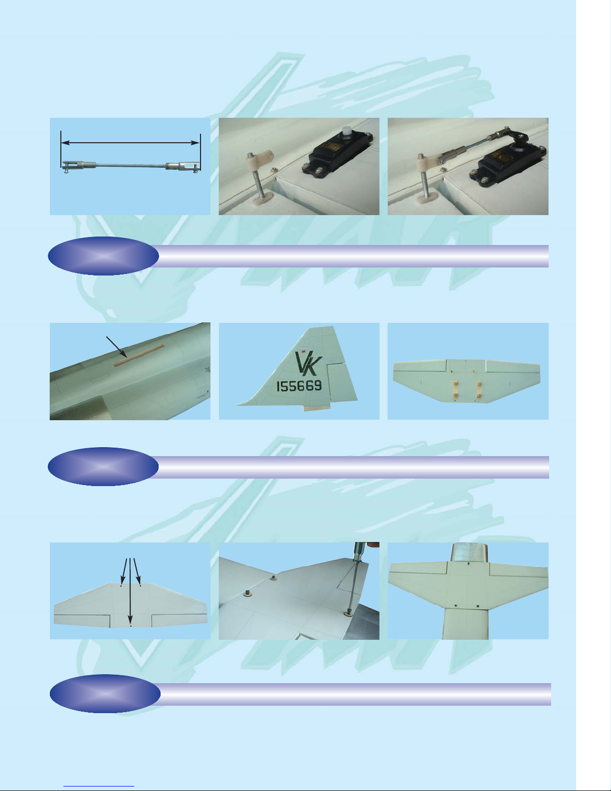
1B- Aileron & aileron servo locations
Aileron servo cavity
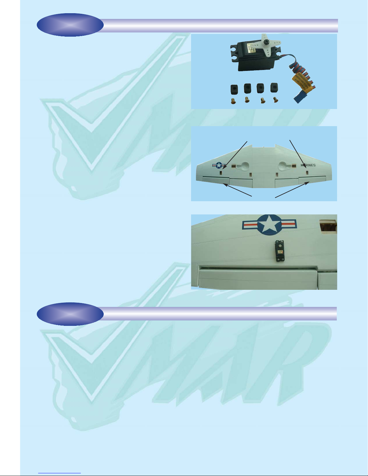
1A- Prepare the servos by fitting the rubber grommets &
ferrules supplied with your servos
To install the aileron servos into the wing you will need the
following items:
- Servos
- Servo mounting screws and grommets as supplied with
servos
- Servo control arms as supplied with servos
- Two aileron control rod assemblies supplied with the kit
The assemblies consist of a metal rod with a clevis on
each end
- Low tack masking tape
- 2 aileron control horn assemblies
Step 1.1 Turn the wing upside down and locate the aileron
servo cavities. See 1B
Step 1.2 Trial fit the aileron servos into their servo mounting
cavities. You may have to modify the cavity slightly to provide clearance for the servo and servo wires. Use a hobby
knife to modify the cavity as required. Most servos have their
output shaft closer to one end than the other. We recommend locating the servo so that the output shaft is as close
to the front of the wing as possible. See 1C
Step 1.3 Screw the servos into place with the screws and
grommets supplied. It is important to install the grommets
and screws correctly. See the manual that came with your
radio for instructions about your particular servo grommets.
See 1C
Step 1.4 Fasten the screws down according to the servo
manufacturers recommended tightness.
Step 1.5 Repeat this procedure for both wing servos.
Aileron
INSTALLING THE AILERON SERVOS INTO THE WING
STAGE 1
1C- Mount the aileron servos into the wing
Step 2.1 Consult your radio instruction manual and center each aileron servo by plugging it into the aileron channel in
the receiver. Turn on the transmitter and then the receiver. Center the aileron trim lever on the transmitter. Remove the
servo arm mounting screw and the servo arm.
Step 2.2 Mount the servo arm back on the servo. Position the arm to be parallel with the back edge of the wing. Screw
the arm into place with the servo arm mounting screw supplied with the servo. Locate the two aileron control rods in the
hardware bag. See 2A. Ensure the clevises are screwed well onto the threaded portion of the rod. Rotate and tug aggressively on the clevises and ensure that they are not loose on the rods. Tape the ailerons into their neutral position so that
they are even with the trailing edge of the wing and not pointing either up or down.
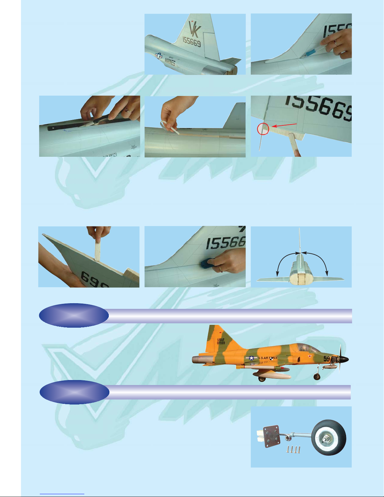
Step 2.3 Ensure that the aileron control horns are screwed onto the threaded aileron control horn bolts and that both control horns are in approximately the same place on their respective bolts. See2B
Step 2.4 Connect the aileron servo rods to the aileron control horns. Connect the control rod to the servo output arm
using a clevis. See 2C
Step 2.5 Connect the other end of the control rod to the control horn using the second clevis. See 2C
Step 2.6 Remove the masking tape holding the aileron.
Step 2.7 In the case of computer radios couple the servos together electronically by connecting them to the appropriate
receiver channels. In the case of analog radios couple the servos together using a Y harness.
INSTALLING THE AILERON CONTROL SYSTEM
STAGE 2
Page 3
3
Step 2.8 Turn on your radio and activate the ailerons, using the aileron stick and ensure a smooth full motion can be
achieved.
Step 2.9 With the wing top side up and viewed from the back, ensure that moving the transmitter aileron stick to the left
raises the left aileron and lowers the right aileron. Movement of the stick to the left will roll the aircraft to the left.
(Counterclockwise roll of the wing when viewed from the back).
Step 2.10 With the wing top side up and viewed from the back, ensure that moving the transmitter aileron stick to the right
raises the right aileron and lowers the left aileron. Movement of the stick to the right will roll the aircraft to the right
2A- Aileron control rod assembly
2B- Aileron control horn installed
2C- Aileron control rod installed
To install the stabilizers into the fuselage you will need:
- Fuselage
- Vertical stabilizer with pre-installed rudder and torque rod
- Horizontal stabilizer with pre-installed elevators
3A- The fuselage slot for the vertical
stabilizer
4A- Horizontal stabilizer bottom face
3B- Vertical stabilizer with preinstalled rudder and torque rod
4B- Install the horizontal stabilizer
onto the fuselage by using three 3-40
[mm] hex bolts and three wooden
washer
3C- Horizontal stabilizer with preinstalled elevators & servo rails
4C- Horizontal stabilizer attached to
the fuselage
Vertical slot
60 mm (2-1/3 in.)
Mounting holes
Step 4.1 Attach the horizontal stabilizer to the fuselage
using three 3 x 40 [mm] hex bolts and three wood washers
(supplied). See 4A, 4B and 4C
To install the vertical stabilizer you will need:
- Vertical stabilizer with pre-installed rudder and torque rod
- 30 minute epoxy
REVIEW THE VERTICAL & HORIZONTAL STABILIZERS
STAGE 3
INSTALL THE HORIZONTAL STABILIZER
STAGE 4
INSTALL THE VERTICAL STABILIZER
STAGE 5
Page 4
4
Step 5.4 Peal away the covering from the contact area in
preparation for applying 30 minute epoxy. See 5D
Step 5.5 Apply sufficient 30 minute epoxy to the lower stabilizer tonque (See 5E) and the bottom of the vertical stabilizer (see 5F) and to the exposed contact area on the top of
the fuselage (See 5D).
Step 5.6 Press the vertical stabilizer into place in the fuselage slot and wipe away any excess epoxy (See 5G).
Step 5.7 Align the vertical stabilizer perpendicular (90
degrees) to the horizontal stabilizer and hold in position with
low tack masking tape until the epoxy cures (See 5H).
Step 5.1 Trial fit the vertical stabilizer
into the fuselage slot. See 5A
Step 5.2 Use a water soluble non-permanent marker to outline the area
where the vertical stabilizer contacts
the top of the fuselage. See 5B
Step 5.3 Use a ruler & sharp hobby
knife to cut the covering just inboard of
the outline marks. See 5C
5C- Use a ruler and sharp hobby knife to
cut the covering just inboard of the outline marks
5D- Remove the covering from the
fuselage
5E- Apply sufficient 30 minute epoxy
to the lower stabilizer tonque. Avoid
the control rod
5A- Trial fit the vertical stabilizer to the
fuselage
5B- Mark an outline around the area
where the vertical stabilizer contacts
the top of the fuselage
5G- Carefully press the vertical stabilizer
into place and remove any excess
epoxy
5H- 90 degree angle between the horizontal and the vertical stabilizer
5F- Apply more 30 minute epoxy to the
bottom of vertical stabilizer
Donot apply the
epoxy here
90
o
INSTALL THE LANDING GEAR
STAGE 6
The F5E TIGER II has a tricycle gear configuration
(trike gear) using a steerable nose wheel and main
landing gear.
Step 7.1 Turn over the wing to locate the pre-drilled main landing gear mounting cavities. See 7B
Step 7.2 Insert the pre-assembled main landing gear into place. Use 4 of the
sheet metal screws to mount each of the main landing gear assemblies to the
wing. See 7C and 7D
7A- Pre-assembled main landing gear
and the sheet metal mounting screws
INSTALLING THE MAIN LANDING GEAR
STAGE 7
Identify the main landing gear components shown below:
- 2 pre-bent main landing gear sets pre-assembled with struts, wheels and
mounting plates.
- 8 sheet metal screws (3x15 mm)
The F5E flaps can function as flaps and/or air brakes. Air
brakes can be quite useful during touchdown and roll out.
Consult an experienced RC pilot before using the air
brakes. Do NOT attempt the use of air brakes on first
flights.
25D- For each flap, connect a control rod between the
servo arm and the flap control horn
25F- Flap deployed
STAGE
After the wing has been attached to the fuselage, install the
wing cover plate.
Page 5

5
Step 8.1 Remove the steering arm from the nose gear assembly . Insert the nose
gear push rod through the EZ-connector. Do not tighten yet. See 8B
Step 8.2 Slide the nose gear wire through the nose gear bearing in the fuselage,
passing the wire through the steering arm. Secure the steering arm to the nose
gear wire by tightening the steering arm set screw. See 8C
Step 8.3 Secure the EZ-connector to the nose gear push rod by tightening the
EZ-connector set screw. See 8D
INSTALLING THE NOSE GEAR
8B- Insert the nose gear push rod
through the steering arm EZ-connector. Do not tighten yet
8C- Secure the steering arm to the
nose gear wire by tightening the
steering arm set screw
8D- Secure the EZ-connector to the
nose gear push rod by tightening the
EZ-connector set screw
8A- Nose gear assembly
Identify the nose gear components per illustration 8A
- 1 completed nose gear assembly with strut and wheel
- 1 steering arm with pre-installed EZ-connector
STAGE 8
FITTING THE FUEL TANK
9B- Fuel tank and stopper assembly (front view)
To assemble the fuel tank you will need the following items:
- The fuel tank and fuel stopper assembly (supplied)
- 2 clunks (supplied)
- About 10 in. (25.4 cm) of medium ID silicone fuel line (DUB-197 or DUB-222 or similar)
9A- Use 2 in. (50 mm) for the pressure line and 4 in. (100
mm) for the refuel line
Pressure line
Pressure line
Fuel line
Fuel line
Refuel and empty line
Refuel line
STAGE 9
7B- Main landing gear location
7C- Mounting the main landing gear to
the wing
7D- Main landing gear mounted to
both wings
Main landing gear location
Page 6

INSTALLING THE ENGINE
STAGE 10
10A- Pre-installed engine mount
10B- Allow for a gap between the spinner back plate and
the fuselage
10C- Mark the location of the engine mounting holes
10D- Drill 3/32 in. (2.5mm) pilot holes at right angles
through the beams
The F5E TIGER II is designed for .60 to .90 2 stroke glow engines; 4 stroke and gas engines are not recommended.
Step 10.1 See 10B. Position and align your engine so that it is pointing straight ahead with a 1/16-3/32 in. (1.5-2.5 mm)
gap between the spinner backing plate and the front of the fuselage.
Step 10.2 Without shifting the engine, use a pencil to mark the location of the engine mounting holes. See 10C
Step 10.3 Remove the engine, center punch the hole location and drill a 3/32 in. (2.5 mm) hole at right angles to and
through the beams. Put a drop of oil in each hole. Use four 4x25 [mm] metal sheet screws (supplied) to mount the engine.
See 10D
Step 10.4 Connect the throttle control rod to the engine throttle arm first. Then place the engine back on the beams and
align the mounting holes. See 10E
Step 10.5 Attach the engine to the beams using four 4x25 [mm] screws (supplied). See 10F
1/16 in. to 3/32 in. (1.5 to 2.5 mm)
9C- Illustration of fuel line positioning inside cutaway of
the tank
Pressure line
Fuel line
Refuel and empty line
9D- Fuel tank installed into the fuselage after adding
external fuel lines from tank forward to engine area
NOSE
TAIL
22A- Cut out the cavity covers using
sharp scissors
The VMAR F5E TIGER II is retract ready. The fixed gear can be replaced with retracts. We have tested with ROBART
#ROB-RB610 nose gear and #ROB-608HD main gear. Please follow instructions that come with the retracts.
If you are NOT installing retracts please do the following:
Step 22.1 Cut out the cavity covers using sharp scissors. See 22A
Step 22.2 Glue the cavity covers into place using CA glue. Use the glue sparingly and do not drip any CA onto the sur-
face. Avoid fingerprints. See 22B and 22C
The dummy fuel tanks can be mounted to the wings using the following proce-
dure:
Step 23.1 Review 23B & 23C and mark the location of the mounting holes for
the aluminum rack outboard of the main landing gear plates. Drill 5/64 in. (2mm)
holes about 3/8 in. (10mm) deep.
Step 23.2 Use sheet metal screws to mount the aluminum rack to the wing. See
23C
Step 23.3 Mount the dummy tanks to the aluminum rails on both wings. See
23D
STAGE
STAGE
CONTROL SURFACE THROW SPECIFICATIONS:
The throws are measured at the widest part of the control
surface. Adjust the position of the pushrods at the control
and/or servo horns to control the amount of throw. You may
23B- Drill the mounting hole
5/8 in.(15 mm)
1-1/3 in.
(35 mm)
Drill the hole with 2mm
diameter, 10mm deep
Page 7

710
11E- Connect the throttle control rod to the engine throttle arm
11F- Attach the engine to beams using four screws (supplied)
Step 11.1 Consult your engine manual and select a suitable propeller.
Step 11.2 Install the thrust washer, the spinner backing plate, the propeller, the prop washer, and the prop nut. Ensure
that they are all firmly attached. See 11B, 11C
Step 1 1.3 Trial fit the spinner cone and spinner cone retaining screw. If necessary enlarge the cutouts in the spinner cone
to allow adequate clearance for the propeller. See 11D
Step 11.4 Double check that the prop nut and spinner cone retaining screw are firmly attached.
11B- Install the spinner backing plate
11C- Install the propeller, the prop washer and the prop
nut
11D- Install the spinner cone using the retaining screw.
Ensure the retaining screw is tight and secure
11A- Aluminum spinner complete with all hardware (supplied)
INSTALL THE PROPELLER AND THE SPINNER
STAGE 11
INSTALLING THE ELEVATOR CONTROL SYSTEM
STAGE 12
Step 12.1 Ths model uses two servos for elevator control.
See 12F
Step 12.2 The elevator torque rods and servo rails are preinstalled. See 12B & 12C
Step 12.3 Install the elevator servos. See 12D & 12F
Step 12.4 Connect the elevator control rods between the
servo arms and the control horns. See 12E
Step 12.5 Adjust the horn positions and control rod lengths
to align and synchronize the elevator movements so that
they are identical. See 12F
Page 8

Step 18.1 Consult your radio manual for instructions about
hooking up your receiver.
Step 18.2 Plan where you are going to put the receiver
with consideration for routing the antenna safely.
STAGE
Step 17.1 Consult your radio manual for instructions about
hooking up your receiver battery, receiver and switch har-
ness.
Step 17.2 Wrap the battery pack securely in foam suitable
for RC equipment and wrap the foam insulated pack in a
plastic bag or cling wrap. Position the battery pack as
shown in 18B.
With the throttle control arm connected to the engine throttle arm ensure that the throttle servo moves the throttle barrel
from nearly closed to fully open.
Adjust the deflection of the control surfaces to match the
specifications on page 11. You can reduce the amount of
throw by doing either or both of the following:
- From the servo end, move the clevis or EZ connector to a
hole in the servo arm that is closer to the servo output shaft.
8
STAGE
14A- Throttle control rod connected to
the engine throttle arm
STAGE
STAGE 16
Step 16.1 Before starting the final set-up of the model,
switch on the radio and ensure that all trims are in their
neutral positions. Check that the aileron, elevator and rud-
der are centered. If any adjustments are needed, do these
by uncoupling the relevant clevis and turning it clockwise to
shorten the linkage or counter - clockwise to lengthen it.
Only when each control surface has been centered
STAGE
TAIL
NOSE
Step 13.1 Align the rudder with the vertical stabilizer and fuselage using a Bulldog paper clamp.
Step 13.2 With the rudder aligned straight with the fuselage. Turn over the fuselage and install the rudder control horn with
the EZ-connector installed. See 13C
Step 13.3 With the rudder aligned straight with the fuselage connect the rudder servo to the receiver and turn on your transmitter. Ensure the rudder servo is centered at neutral.
Step 13.4 Connect the rudder control rod between the rudder servo arm and the rudder control horn EZ-connector. Tighten
the EZ-connector set screw firmly and ensure it is secure. Use medium thread locker (Blue). See 13D
Step 13.5
Connect the nose gear steering rod to the opposite side of the rudder servo arm. See 13D
13B- Align rudder with Bulldog paper clamp
13A- Rudder control horn assembly
13D- Rudder control rod installed between the rudder
servo and rudder control arm. Nose gear steering rod
connected to opposite side of servo arm
13C- Rudder control horn installed on the rudder control
rod
INSTALLING THE RUDDER
& NOSE WHEEL CONTROL SYSTEM
STAGE 13
TAIL
NOSE
12B- Pre-installed elevator torque
rods & servo rails
12A- Elevator control rod assembly
12C- Control horns pre-installed on
the elevator torque rods
12D- Mount the servos on the preinstalled servo rails
12E- For each servo, connect the con-
trol rod between the servo arm and
the control horn
12F- Elevator servos and control rods
installed
2-1/2 in. (65 mm)
Page 9

Step 18.1 Consult your radio manual for instructions about
hooking up your receiver.
Step 18.2 Plan where you are going to put the receiver
with consideration for routing the antenna safely.
Step 18.3 Wrap the receiver securely in foam suitable for
RC equipment and wrap the foam insulated receiver in a
plastic bag or cling wrap.
Step 18.4 Install your receiver near the aft end of the fuselage as shown in 18B.
INSTALLING THE RECEIVER BATTERY
STAGE 17
Step 17.1 Consult your radio manual for instructions about
hooking up your receiver battery, receiver and switch harness.
Step 17.2 Wrap the battery pack securely in foam suitable
for RC equipment and wrap the foam insulated pack in a
plastic bag or cling wrap. Position the battery pack as
shown in 18B.
Step 17.3 Thread the battery pack connector forward in
preparation for connecting to your switch harness.
Step 17.4 Connect the battery pack connector to your
switch harness according to your radio manual.
With the throttle control arm connected to the engine throttle arm ensure that the throttle servo moves the throttle barrel
from nearly closed to fully open.
Adjust the deflection of the control surfaces to match the
specifications on page 11. You can reduce the amount of
throw by doing either or both of the following:
- From the servo end, move the clevis or EZ connector to a
hole in the servo arm that is closer to the servo output shaft.
- From the control horn end, move the horn out further on
the threaded bolts. Always confirm that the horn is still
thoroughly engaged with the threaded bolt after you have
adjusted it.
CONNECTING THE THROTTLE CONTROL
STAGE 14
14B- The throttle servo controls the
engine throttle using the throttle control rod
14C- Completed engine with throttle
control connected and muffler
installed
14A- Throttle control rod connected to
the engine throttle arm
ADJUST CONTROL SURFACE THROW LIMITS
9
STAGE 15
FINAL RC SET-UP
STAGE 16
Step 16.1 Before starting the final set-up of the model,
switch on the radio and ensure that all trims are in their
neutral positions. Check that the aileron, elevator and rudder are centered. If any adjustments are needed, do these
by uncoupling the relevant clevis and turning it clockwise to
shorten the linkage or counter - clockwise to lengthen it.
Only when each control surface has been centered
mechanically in this way should you begin adjusting the
surface movement (or throw).
Step 16.2 Now confirm that the control surfaces are moving in the correct direction. Use the servo reversing switches on your transmitter to reverse the direction of a servo if
necessary.
INSTALLING THE RECEIVER
STAGE 18
TAIL
Throttle
control rod
NOSE
Page 10

11E- Connect the throttle control rod to the engine throt-
tle arm
Step 11.1 Consult your engine manual and select a suitable propeller.
Step 11.2 Install the thrust washer, the spinner backing plate, the propeller, the prop washer, and the prop nut. Ensure
that they are all firmly attached. See 11B, 11C
Step 1 1.3 Trial fit the spinner cone and spinner cone retaining screw. If necessary enlarge the cutouts in the spinner cone
to allow adequate clearance for the propeller. See 11D
Step 11.4 Double check that the prop nut and spinner cone retaining screw are firmly attached.
11C- Install the propeller, the prop washer and the prop
nut
11A- Aluminum spinner complete with all hardware (sup-
plied)
STAGE
STAGE 12
Step 12.1 Ths model uses two servos for elevator control.
See 12F
Step 12.2 The elevator torque rods and servo rails are pre-
installed. See 12B & 12C
Step 12.3 Install the elevator servos. See 12D & 12F
18A- Receiver location 18B- Receiver battery location
Receiver
Receiver
Battery
CONFIRM RADIO OPERATION
STAGE 19
BALANCING THE AIRCRAFT
STAGE 20
CONFIRM MECHANICAL INTEGRITY
STAGE 21
Step 19.1 Consult your radio manual for instructions about
testing and operating your radio system.
Step 19.2 Pay particular attention to charging your radio
system batteries and range testing the system before and
after each flight.
Step 19.3 Check that all controls are working correctly
before and after each flight.
The CG for your F5E TIGER II is located at 8-7/8 in. to
9 in. (225 - 230 mm) back from the leading edge of the wing
when the wing has been attached to the fuselage.
For the initial flight, the CG should be located at 8-7/8
in. (225mm) back from the leading edge of the wing when
the wing has been attached to the fuselage.
The CG is measured with the engine, radio gear and all
other components installed but WITH NO FUEL IN THE
TANK.
It is very important to have the CG correct. Flying your
model with the CG too far back will likely lead to loss of
control and a crash. If you discover that after you have
assembled your model and installed your radio and engine
that the CG of your model is incorrect you must bring the
CG to the correct location by doing the following BEFORE
FLYING :
- Move the battery pack fore or aft.
- Move other components fore or aft.
- Change engine to a lighter or heavier model.
- Add weight to the nose or tail. If adding weight to
the nose, try to make it useful by going to a heavier duty
engine or adding a spinner with a heavy metal backing
plate. As a last resort, add stick on “dead” weight where
appropriate.
Once you have confirmed that the CG is correct, you
should do a thorough review of the entire model before your
first flight. Check everything twice! Every hook up, every
coupling, everything! Do it twice!!
Before your first flight, have an experienced flyer review
your work. Do not fly your model until it has been checked
out by a third party who knows how to fly and how to set up
a model aircraft. Do not fly alone. Seek experienced help.
Once you have completed your first flight, get in the habit of
checking your model over before and after each flight! Don’t fly
if you find something that is not right!
8-7/8 in.(225mm)
9 in.(230mm)
TAIL
NOSE
Page 11

116
22A- Cut out the cavity covers using
sharp scissors
22B- Glue the main gear cavity covers
into place using CA glue
22C- Glue the nose gear cavity cover
into place using CA glue
The VMAR F5E TIGER II is retract ready. The fixed gear can be replaced with retracts. We have tested with ROBART
#ROB-RB610 nose gear and #ROB-608HD main gear. Please follow instructions that come with the retracts.
If you are NOT installing retracts please do the following:
Step 22.1 Cut out the cavity covers using sharp scissors. See 22A
Step 22.2 Glue the cavity covers into place using CA glue. Use the glue sparingly and do not drip any CA onto the sur-
face. Avoid fingerprints. See 22B and 22C
The dummy fuel tanks can be mounted to the wings using the following procedure:
Step 23.1 Review 23B & 23C and mark the location of the mounting holes for
the aluminum rack outboard of the main landing gear plates. Drill 5/64 in. (2mm)
holes about 3/8 in. (10mm) deep.
Step 23.2 Use sheet metal screws to mount the aluminum rack to the wing. See
23C
Step 23.3 Mount the dummy tanks to the aluminum rails on both wings. See
23D
INSTALL THE DUMMY WING TANKS
INSTALL LANDING GEAR CAVITY COVERS
STAGE 22
STAGE 23
CONTROL SURFACE THROW SPECIFICATIONS:
The throws are measured at the widest part of the control
surface. Adjust the position of the pushrods at the control
and/or servo horns to control the amount of throw. You may
also use ATV's if your radio has them but the mechanical
linkages should still be set so that the ATV's are near 100%
for best servo resolution.
Low rate High rate
ELEVATOR 1/3 “ (8mm) up 3/8” (10 mm) up
1/3 “ (8mm) down 3/8” (10 mm) down
AILERON 3/16” (5 mm) up 3/8” (10 mm) up
3/16” (5 mm) down 3/8” (10 mm) down
RUDDER 5/8 “ (16 mm) right 1” (25 mm) right
5/8 “ (16 mm) left 1” (25 mm) left
23B- Drill the mounting hole
23A- Dummy wing tanks and mounting
rails
23C- Mount the mounting rails to the
wing
23D- Mount the dummy tanks to the
aluminum rails on the wings
5/8 in.(15 mm)
1-1/3 in.
(35 mm)
Drill the hole with 2mm
diameter, 10mm deep
Page 12

Step 8.1 Remove the steering arm from the nose gear assembly . Insert the nose
gear push rod through the EZ-connector. Do not tighten yet. See 8B
Step 8.2 Slide the nose gear wire through the nose gear bearing in the fuselage,
passing the wire through the steering arm. Secure the steering arm to the nose
gear wire by tightening the steering arm set screw. See 8C
Step 8.3 Secure the EZ-connector to the nose gear push rod by tightening the
EZ-connector set screw. See 8D
8B- Insert the nose gear push rod
through the steering arm EZ-connec-
tor. Do not tighten yet
Identify the nose gear components per illustration 8A
- 1 completed nose gear assembly with strut and wheel
- 1 steering arm with pre-installed EZ-connector
STAGE
12
To assemble the fuel tank you will need the following items:
- The fuel tank and fuel stopper assembly (supplied)
- 2 clunks (supplied)
- About 10 in. (25.4 cm) of medium ID silicone fuel line (DUB-197 or DUB-222 or similar)
9A- Use 2 in. (50 mm) for the pressure line and 4 in. (100
mm) for the refuel line
Refuel and empty line
STAGE
7B- Main landing gear location
Main landing gear location
INSTALLING OPTIONAL FLAPS &/OR AIR BRAKES
24A- Dummy missile and mounting rack
24B- Install the mounting rack to the wing tip using 2
screws 2x10 [mm]
24C- Install the dummy missile to the mounting rack
24D- Secure the missile to the mounting rack by using 2
screws, 1 in the top...
24E- ...and 1 in the bottom
24F- Repeat the procedure shown in 23B - 23F for the
other missile
25A- Flap servo locations
INSTALL THE DUMMY MISSILES
STAGE 24
STAGE 25
The VMAR F5E TIGER II comes with wing tip dummy missiles. To install the dummy missiles you will need:
- 2 missile mounting racks (1 left and 1 right)
- 2 missiles (1 left and 1 right)
- 8 screws 2x10 [mm]
Your model comes with optional flaps that can also be configured as air brakes.
To install the optional flaps &/or air brakes you will need:
- 2 flap/air brake control rods (supplied)
- 2 standard servos (not supplied)
2x10 srcews
Flaps
Flap servos location
25B- Flap/Air brake control rod
2-1/3 in. (60 mm)
Page 13

13
The F5E flaps can function as flaps and/or air brakes. Air
brakes can be quite useful during touchdown and roll out.
Consult an experienced RC pilot before using the air
brakes. Do NOT attempt the use of air brakes on first
flights.
25C- Install the servos and flap control horns. Connect the
flap control rods to the servo arms
25D- For each flap, connect a control rod between the
servo arm and the flap control horn
25E- Flap/Air brake normal position
25F- Flap deployed
25G- Air brake deployed
INSTALL THE WING COVER
26A- Wing cover
STAGE 26
After the wing has been attached to the fuselage, install the
wing cover plate.
2-1/3 in. (60 mm)
Page 14

Step 2.8 Turn on your radio and activate the ailerons, using the aileron stick and ensure a smooth full motion can be
achieved.
Step 2.9 With the wing top side up and viewed from the back, ensure that moving the transmitter aileron stick to the left
raises the left aileron and lowers the right aileron. Movement of the stick to the left will roll the aircraft to the left.
(Counterclockwise roll of the wing when viewed from the back).
Step 2.10 With the wing top side up and viewed from the back, ensure that moving the transmitter aileron stick to the right
raises the right aileron and lowers the left aileron. Movement of the stick to the right will roll the aircraft to the right
2A- Aileron control rod assembly
To install the stabilizers into the fuselage you will need:
- Fuselage
- Vertical stabilizer with pre-installed rudder and torque rod
3A- The fuselage slot for the vertical
stabilizer
4A- Horizontal stabilizer bottom face
Step 4.1 Attach the horizontal stabilizer to the fuselage
using three 3 x 40 [mm] hex bolts and three wood washers
(supplied). See 4A, 4B and 4C
To install the vertical stabilizer you will need:
- Vertical stabilizer with pre-installed rudder and torque rod
- 30 minute epoxy
STAGE 3
STAGE 4
STAGE
14
26B- Trim the wing cover plate using sharp scissors. See
26C
26C- Wing cover plate after trimming with sharp scissors
26D- Carefully align the clearance holes in the wing cover
plate to ensure access to the wing bolts. Then use CA to
attach the cover plate to the wing
26E- Wing cover plate installed
HAPPY FLYING!
Note
For parts and support related to this product please visit us at www.richmondrc.com/support.htm
For more VMAR products please visit us at www.richmondrc.com
Page 15

15
Note
Page 16

Model airplanes, model engines, model engine fuel, pro-
pellers and related accessories, tools and equipment can be
hazardous if improperly used. Be cautious and follow all safe-
ty recommendations when using your VMAR model airplane.
Keep hands, tools, clothing and all foreign objects well clear of
engines when they are operating. Take particular care to safe-
guard and protect your eyes and fingers and the eyes and fin-
gers of other persons who may be nearby. Use only a good
quality propeller that has no cracks or flaws. Stay clear of the
propeller and stay clear of the plane of rotation defined by the
propeller. The Manufacturer, Distributor, Retailer and/or other
A Remote Control Model Aircraft is not a toy. It is a fly-
ing model that functions much like a full size airplane. If
you do not assemble and operate this product properly
you can cause injury to yourself and others and damage
property. DO NOT FLY this model if you are not qualified.
You are entirely responsible for the mechanical,
Agreement With & Acceptance of the following Liability Disclaimer
ASSEMBLY & OPERATIONS MANUAL
Please review this manual thoroughly before assembling or operating this model
Note
VMAR, V-COTE 2-3DS, VMAX and VCAare Trademarks of VMAR Manufacturing Inc. and appointed agents worldwide
Copyright VMAR Manufacturing Inc. 20050916
 Loading...