

Page 1
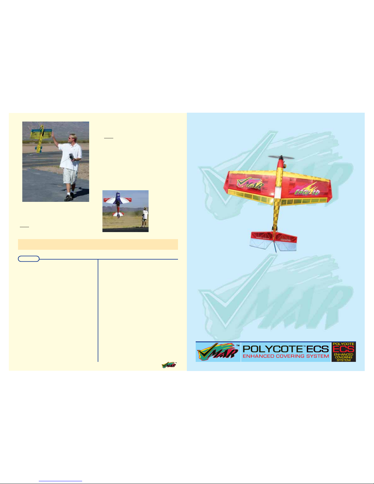
VMAR - EASY 3D
FUN SPORT MODEL
Assembly
and
Operations Manual
Please review this manual throughly
Before assembling or Operating
the
VMAR-EASY 3D
FUN SPORT MODEL
VMAR - EASY 3D
Before proceeding please check for additional information
related to this model at www.richmondrc.com
16 Assembly and Operations Manual VIMAR - EASY 3D FUN SPORT MODEL
their thumb/finger prefer not to have so much Expo. It’s all in how it
feels to you, the pilot.
Power. The general rule of thumb is that you need a 2:1 power-
to-weight ratio. This gives you the ability to hover at a throttle setting
of less than full power and leaves you with reserve to get out of
those bad situations. Generally when I am hovering it is at 1/4 to 1/3
throttle. When hovering down low, there isn’t much room for error, so
having the ability to punch out of a bad situation is a must. This extra
power also allows for variances in the type of hovering you do.
Focus. There are 2 things I focus on when hovering, one is visu-
al visual and the other is mental. The visual portion is just that,
where are my eyes looking? I personally look at the canopy area of
the plane when hovering. This way I can see the whole airplane. I
also know that if the rear of the canopy is below my eye level, I am
about to touch the rudder to the ground. But generally I try to see the
whole plane, this gives me the best idea of the actual attitude of the
plane and the control inputs I need to give it. The mental aspect of
hovering is to think ahead of what the airplane is going to do. While
torque rolling, I try to think at least 1/2 rotation ahead of the plane.
So if I am looking at the bottom of the plane, I visualize, in advance,
what is going to happen when the plane rotates to the point that I can
see the top side—and I begin to make any needed corrections while
still looking at the bottom. Good luck to all who choose to explore
this exciting maneuver!
Jason Shulman, among the
top RC aerobatic and 3D
pilots in the world, has been
flying since he was three
and competing since 1981.
Jason has won several
top-5 finishes at the
Tournament of Champions
(TOC) and has taken 4th at
the FAI World’s competition. For more detail on
Jason’s life as a top RC
pilot, checkout a fascinating
interview with Jason at
RCUniverse.com.
Jason flies his Exhila 3D electric, available from Jason’s Model
Concepts (JMC). JMC offers innovative aircraft optimized for aerobatics and 3D flying. For more information,
visit: www.jasonshulman.com/jasonsmodelconcepts.
Note
Reprinted courtesy of FLY RC magazine. Copyright 2004 by Maplegate Media Group. All rights reserved.
FLY RC published monthly for RC Aircraft enthusiasts. FLY RC is available at your local Hobby Retailer or Magazine Store.
Page 2
2 Assembly and Operations Manual VIMAR - EASY 3D FUN SPORT MODEL
Model airplanes, model engines, model engine fuel,
propellers and products such as the EASY 3D semi scale
sport model can be hazardous if improperly used. Be
cautious and follow all safety recommendations when
using your Model . Keep hands, tools, clothing and all
foreign objects well clear of engines when they are
operating. Take particular care to safeguard and protect
your eyes and fingers and the eyes and fingers of other
persons who may be nearby. Use only a good quality
propeller that has no cracks or flaws . Stay clear of the
propeller and stay clear of the plane of rotation defined by
the propeller.
The Manufacturer, Distributor, Retailer and/or other
suppliers of this product expressly disclaim any
warranties or representations, either expressed or
implied, including but not limited to implied warranties of
fitness for the purposes of achieving and sustaining
remotely controlled flight.
In no event will the Manufacturer, Distributor, Retailer
and/or other suppliers of this product have any obligation
arising from contract or tort, or for loss of revenue or
profit, or for indirect, special, incidental, consequential or
other damages arising from the use of this product.
In purchasing and/or using this product, the user accepts
all responsibility for its use and accepts all liability
associated with such use.
Liability Disclaimer
It is important that the following liability disclaimer be
READ BEFORE ASSEMBLING OR USING THIS PRODUCT.
A Remote Control Model Aircraft is not a toy. It is a
flying model that functions much like a full size airplane.
If you do not assemble and operate this product
properly you can cause injury to yourself and others
and damage property. DO NOT FLY this model if you
are not qualified.
You are solely responsible for the mechanical, aeronautical and electrical integrity of this model and it’s structure,
control surfaces, hinges, linkages, covering, engine,
radio, wiring, battery and all other components check all
components before and after each flight. Do not fly until
it’s right!
Proceeding with assembly and use of this product Indicates
Agreement With and Acceptance of the Liability Disclaimer .
CAUTION.
- This model is designed and constructed to be very
light for 3D maneuvers at low to moderate speed
and light to moderate stress.
- This model is not designed or manufactured for
high speed flight.
- Do NOT fly at high speeds under full throttle. The
model may break up suddenly if flown at high
speeds under full throttle.
- Do NOT fly on horizontal straight line at full
throttle as sudden brake up during flight is
possible.
- Full throttle should only be used for climbing
vertically, loops and rolls or in the case of an
emergency where power is needed.
- When descending, reduce your power setting
immediately. Do not allow the model to accelerate
to high speeds in a dive.
- Do NOT overpower this model. Normal operation
requires only half throttle.
- Careful use of the throttle is required to prevent
breakup of this model in flight. Do not overpower
or overstress this model.
- This model is for intermediate and advanced RC
model pilots. It is NOT suitable for beginners.
- This model has been flight tested with snap-rolls
and other aerobatic maneuvers. Do NOT overstress the airframe with repetitive, violent, extreme
or high speed maneuvers.
- Inspect this model thoroughly before and after
each and every flight. Watch for stress cracks,
loose joints or other abnormalities. Repair any
defects before flying.
- Be alert for unexpected and/or irregular responses
during flight. Slow down, reduce stress on the
airframe and land immediately if flight response is
compromised in any way.
- Check all linkages, hinges, components and
control surfaces before and after each flight.
Although this model may be partially
pre-assembled you are solely responsible for the
integrity and flight worthiness.
- Do NOT overpower this model. This model is
designed for 2 stroke .46-.52 sized glow fueled
engines OR similar power four stroke engines or
similar output electric motors. Overpowering this
model will result in airframe failure.
WWAARRNNIINNG
G
Assembly and Operations Manual VIMAR - EASY 3D FUN SPORT MODEL 15
THRUST TO WEIGHT RATIO
The engine must be able to lift the plane vertically, which is a combination of propeller selection and fuel. You need a power to weight
ratio of at least 1.5 to 1. We do not want to hover at full throttle, we
want to ideally hover at half throttle. We need the reserve power
because we are vectoring propwash off the ailerons to generate the
high degree of roll, and this robs lift and requires the increase in
throttle. A high speed torque roll requires the most power, in the
order of 2:1 just to maintain altitude! Suffice to say that this is a very
advanced hovering maneuver! You need a very reliable engine.
Hovering is great until the noise stops!
Do not use an engine that has a history of running hot or lean. On
the average .40 powered ship, look to configure your plane with a
“heli-like” setup. By this I mean, choose a prop with the biggest
diameter and lowest pitch which will function with the landing gear
and flight envelope of your plane. I have found that the 11x4 prop is
outstanding for hovering with most .40 powered planes. The engines
swing it easily, (you do not want to over heat), and the four inch pitch
generates gobs of thrust at lower flight speeds.
Fuel selection is important. Since we are trying to hover at half of
our available throttle, consider using a higher nitro fuel. The more
nitro, the cooler the engine runs. This is because the nitro brings
more oxygen into the engine and this is where the power boost and
substantial cooling takes place. High Nitro causes harm when you
are at high throttle settings and at rpm’s that overcome the cooling
effects of the nitromethane.
FLYING
You might think that heli experience is helpful, but there are conflicts
with that logic. When you stand your plane on its tail, the yaw axis is
controlled by your ailerons, not the rudder. The rudder, (left stick) controls the roll axis! Heli pilots need to teach their fingers some new
tricks or they will find themselves in trouble!
The throttle, of course, is no longer fast and slow, it is now for rising and decending. There is no “chopping the throttle” when you get
in trouble here! Try that, and you will find that tail first impacts break
things on your plane that you have never seen broken before.
Start with transitioning to hover by practicing holding higher and
higher angles of attack and learning how much throttle to add to
compensate for the lost lift, no longer generated by the wings. As
you pass through the 45 degree angle point, you will find that your
speed drops almost to zero very quickly. You’ll need the most right
rudder at around 45 degrees. As you approach vertical, you’ll find
that most planes still want some right rudder, even when hanging
vertically. I believe this has more to do with countering torque than
any other factor, whereas the rudder compensation at the 45 degree
angle is almost all due to “P” factor. (more on “P” factor in a future
column).
If your plane needs too much throttle to make the transition and
you constantly end up gaining altitude in order to get the plane into
the vertical position, this suggests that you are nose heavy, or lacking in elevator authority needed to swing the tail under the plane.
Running the CG aft of the recommended area is tricky business, but
it can make all the difference in a stable transition. Practice is the
key, but keep a careful eye on the fuel tank and the air/fuel mixture
feeding the engine. You can’t afford for the engine to go lean now!
Flying into and out of a stable hover requires power. If your plane
does not have a low wing loading, you may find that it belly flops
when you go to exit the hover. This is due to the rapid transition back
to “wing-borne” flight—this transition may leave you at such a low
airspeed that the wings won’t to hold the plane up. Expect that the
plane will need a boost of power to get it back to “horizontal” flying
speed! Give it this boost just as it starts to pitch over.
Like your first landings, a quality performance takes practice. Start
a bit on the high side to see how your plane behaves and stick with
it. Soon you will be hanging in space. One thing that hovering teaches you is to be a master of your left hand!
Good Luck-Dave Baron
Editor’s note: we asked noted TOC pilot Jason Shulman whether
hovering smaller models was different from hovering large TOC-size
aircraft, and also for his views on the basics of hovering, from setup
to pilot focus.
Jason Shulman: I recently had a great opportunity to judge this first
hand at the Joe-Nall giant scale fly-in. I was hovering my Exhila (one
pound all up weight) on both calm days and windy days. I was also
hovering a few 30% and larger planes during these same conditions.
The first thing I noticed is that in calm conditions, there was really no
difference. Everything was smooth and predictable. But the windy
conditions posed a few differences. The small plane was very sensitive to the wind in hover. Not so much in terms of drift, because
even the large planes drifted. But the slight variances in the wind
would throw the Exhila around, while not really bothering the larger
planes.
I also noticed that the smaller plane would hover, at times, at a 45degree angle (leaning into the wind), whereas the larger planes
would hover at about a 15-20 degree angle in the same winds. This
made the smaller plane much harder to hover. Once you start pushing to a 45-degree angle, you are entering a kind of forward flight
with the associated flight characteristics. So not only are you trying
to balance the plane on its tail, but you are also trying to keep it from
flying forward.
Although both large and small hovering planes will drift in the wind,
one of the most apparent differences is the speed of the drift. When
I hovered the large planes, drift was relatively slow, and smooth
looking. The Exhila was a different story: it scooted across the field
like it was flying level at 1/3 power.
SETUP
When setting up a plane to hover, regardless of size, you follow the
same principles.
Center of Gravity (CG). The CG should be slightly aft so that
the plane is slightly tail heavy as compared to the normal, or recommended, flying CG position. The larger the plane, the larger the CG
range is. On my Exhila, moving the CG back 1 inch can cause it to
be very unstable and almost impossible to fly. On my TOC planes, I
can move the CG back 3-4 inches and they will still be controllable.
Generally, I move the CG back 1/2 in. at a time on the larger planes,
and 1/8 in. on the smaller planes. There is also a point where you
can have the CG back too far and hovering becomes harder to perform.
Control Throws. I have found it best to fly with dual-rates. I set
a low rate, which is good for general or pattern flying and then max
out all of the surfaces for a high rate of roughly 45-degrees of deflection for hovering. I fly thumbs, so I like a little bite of Exponential on
my low rates and a much higher setting on my high rates. My set-up
on Expo is for a “soft-center” feel on both rates. Pilots that fly with
HOVERING TIPS FROM
THE MASTER
by Jason Shulman
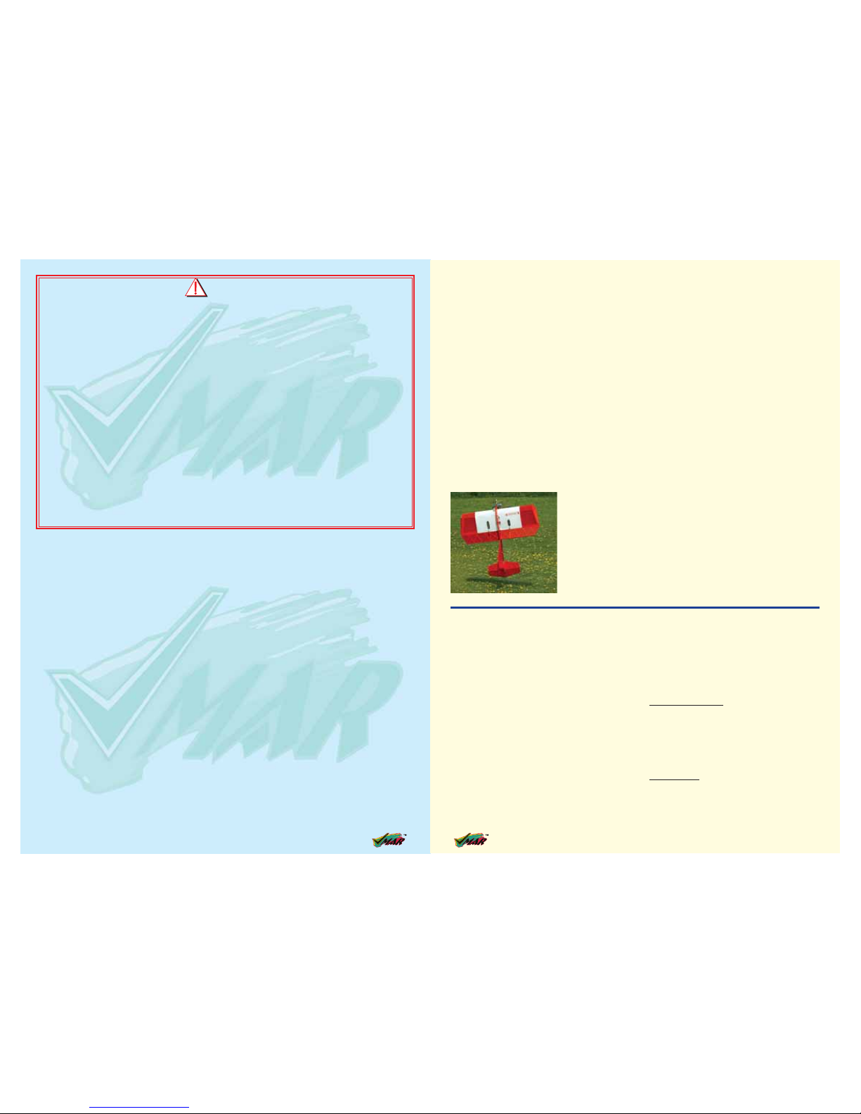
The closer you are to the
ground, the faster you
detect, and can react to,
which way you are drifting.
Note that the tail feathers
and the servo gears that
push them are a bit fragile
and not used to contacting
the ground before more
rugged parts of the plane
do!
Page 3

Assembly and Operations Manual VIMAR - EASY 3D FUN SPORT MODEL 3
INDEX
Step No. Page No.
Warning, Liability Disclaimer and Caution 2
Introduction 3
Review Packing List, gather your tools & shop materials 3 - 4
Installing the wing 1 5
Fitting aileron servo 2-3 5-6
Installing the horizontal & vertical stabilizer 4-11 7-9
Installing the main landing gear 12 9-10
Installing the tail wheel 13 10
Installing the fuel tank 14 10
Installing the engine 15 11
Fitting rudder and elevator control horns 16 11
Connecting the pushrod to the elevator 17 11
Connecting the pushrod to the rudder 18 12
Connecting the throttle control 19 12
Adjust control surface throw limits 20 12
Final RC setup 21 12
Installing radio equipment 22-25 12-13
Balancing the aircraft 26 13
Confirm mechanical integrity 27 13
CG and throw specifications 28 14
Thank you for purchasing a VMAR product. VMAR
Manufacturing is committed to delivering superior value
to the RC modeler. Your new EASY 3D is the
market leader in features, ease of use and flexibility.
Please review these instructions before beginning the
simple assembly procedure.
We’ve used metric measurements throughout these
instructions. We know that some of you like metric while
others think that furlongs per fortnight makes a nifty velocity
indicator. If you are in the furlong camp, bear with us….
It’s not a big deal…3 millimeters is stated as 3mm and
3mm is about 1/8 of an inch. Fire up your calculator and
you will find that 25.4 mm makes an inch. In places where
you have to actually set up something according to a
recommended measurement, we’ve listed an
approximate imperial measurement in inches in brackets.
Whenever we’ve used the directional terms left or right ,
they are with respect to the model when viewed as you
would when sitting in the cockpit…that is when viewed
from the back looking forward.
INTRODUCTION
You’ve taken the lid off the box and grabbed the instruction
booklet…you are about 6-8 hours away being ready to go
flying! Now is the time to look over what’s in the box.
Please see the included Packing List and review the
contents and make sure nothing has been damaged in
shipping. Damage or missing components must be
reported to your vendor BEFORE any assembly begins.
Please DO NOT START if something is damaged or
missing. As you can imagine, once you join the wing halves
attach the stabilizers or install your radio or engine your
options for returns are very limited. Your vendor will not be
able to provide you with exchanges or replacements of
parts that have been assembled. DO NOT START
UNLESS IT’S RIGHT!
REVIEW PACKING LIST, GATHER YOUR TOOLS & SHOP MATERIALS.
CHECK OFF OPTIONAL EQUIPMENT AND ACCESSORIES.
- These items are not included and are not required but
make the operation of your EASY 3D and most
other remote control aircraft easier & more enjoyable.
- Power Tote Deluxe field box # VMA-PT109D
- Fuel pump and connecting tubing
- Fueling valve
- Chicken stick or electric starter
- Stick on weights
- Battery to power electric starter
- Battery charger
- Power Panel to manage starter and pump if electric.
- Extra propellers
- Extra Glow Plugs
- Misc Tools
- Engine test stand # VMA – ETS120
14 Assembly and Operations Manual VIMAR - EASY 3D FUN SPORT MODEL
40mm
1 9/16"
40mm
1 9/16"
35mm
1 3/8"
35mm
1 3/8"
Elevator Aileron
40mm
1 9/16"
40mm
1 9/16"
Rudder
Control Surface Movement
ELEVATOR 40mm (1-9/16") up
40mm (1-9/16") down
RUDDER 40 mm (1-9/16”) right
40 mm (1-9/16”) left
AILERON 35 mm (1-3/8”) up
35 mm (1-3/8”) down
C.G. AND THROW SPECIFICATION
Step 28
REPLACEMENT PARTS & ACCESSORIES:
In the event that you require replacement parts or accessories for this model please contact your retailer or order OnLine at www.richmondrc.com
MORE INFORMATION:
For other information related to this product please see
www.richmondrc.com
Hovering explained!
I am really glad to be writing this new column and especially to be
a contributor to Fly RC Magazine! This magazine is going to be the
place to discover and learn about the best and coolest gear, and this
column is where you will learn to sharpen your piloting skills! It is a
special interest group within the AMA that is dedicated to hyper
maneuverable flight and pitting you and your plane against the topwatch! If you have ever considered yourself a hot pilot, show up at
one of their contests and prepare to be amazed. Check them out at
www.ncffafunfly.org
HOVERING
What is the attraction to hanging your plane on its nose and holding it otionless and in full control? Simple answer, it’s cool! I am going
to explore the phenomenon, the kinds of planes that hover best and
what you need to know to teach yourself this great flying skill.
PLANES, ENGINES AND PROPS
The most important aspect of your selecting a plane to hover is its
weight. Your plane must be light. Secondly, you need to have substantial control surfaces on the rudder, elevator and ailerons that are
in the prop blast of the engine. Planes that have ailerons
only on the outboard section of the wing are unsuitable,
because with no airflow over the ailerons, there is no control in hover no matter how far you deflect them!
I have found that planes with longer fuselages, while
more stable in pitch, are not necessarily good for hovering. This is because the rudder and elevator are too far
from the slipstream of the prop. You need a strong slipstream over the tail feathers for control.
There are several ways to improve an airplane’s ability to
hover. One is to move the CG aft incrementally—a little at
time so that you can test the result. An aft CG helps a lot in
the transition from normal flight to hover and back, but use
care, as you do not want to go so far that you give up your
stability in normal flight! Another concern is flaperons that
are coupled to the elevator. While this gives the tightest
loops on most fun-fly planes, it does not help in hovering.
In hover, flap deflection on most models sends the plane in
the opposite direction (in pitch) than you desire. I advise
that you turn off this function, or turn it down so less than
10 percent of flap throw is mixed into elevator throw.
FREESTYLE
by Dave Baron daveb@flyrcmag.com
My Minus is a great hovering plane that transitions easily to
hover without gaining altitude. It is light, with an aft center of
gravity that is at 35% of the wing chord (from wing leading
edge to aileron trailing edge). The Minus is a Skipp Turner
design. You can reach Skipp at airworthy@aol.com.
Page 4

4 Assembly and Operations Manual VIMAR - EASY 3D FUN SPORT MODEL
CHECK OFF TOOLS AND SHOP MATERIALS NEEDED.
These tools and shop materials are not included and are
required to complete and operate your EASY 3D and most
other remote control aircraft.
- Clean and flat table or work surface approximately
600 x 1800 mm (24 x 72 in)
- 2.5 mm ball socket screw driver or Allen wrench
- 3.0 mm ball socket screw driver or Allen wrench
- 4.0 mm ball socket screw driver or Allen wrench
- Phillips (cross head) screw driver small size
- Phillips (cross head) screw driver medium size
- Flat blade screw diver medium size
- Low tack masking tape.
- Ruler or tape measure
- Side (“wire”) cutters
- Pencil, pliers and hobby knife with #11 blade
- 30 minute Epoxy and 240 grit sandpaper
- Silicon Based Sealant (Dap – A – Goo)
- Epoxy mixing dishes, brushes and sticks
- Paper towels
- Rubbing alcohol
- Crescent wrench (optional)
- Heat gun and heat iron for covering
(optional for covering touch up)
CHECK OFF OTHER ITEMS NEEDED TO COMPLETE EASY 3D FUN SPORT MODEL
- These items are not included and are required to
complete and operate your VMAR MODEL and most
other remote control aircraft.
- Medium fuel tubing appropriate for your choice of
engine and fuel. 500 – 750 mm ( 24-36 in.)
- Liquid thread locker
- RC FM radio with at least four channels of control and
on a frequency appropriate for your market area.
- Five servos compatible with the RC FM Radio.
Servos generally are sold with new radio systems
- External Switch Actuator appropriate for your radio
system (optional)
- Engine and muffler suitable for use in a remote control
model aircraft. A two stroke glow fuel .40-.52 cubic inch
engine is recommended
- Propeller suitable for the engine. See the engine instruction
manual recommendation for diameter and pitch.
- Engine glow plug
- Engine glow plug igniter
- Engine 4 way wrench
- Fuel for the engine
- “After run” oil for engine
- RC Foam sheeting for wrapping radio receiver
and battery pack.
CHECK OFF COMPONENTS AND PARTS INCLUDED.
Major components and sub-assemblies
- 01 Fuselage (pre-installed engine mount)
- 02 Wing halves (left and right)
- 01 Vertical stabilizer with pre-installed rudder.
- 01 Horizontal stabilizer with pre-installed elevator .
- 01 Fiberglass cowl
- 01 Landing gear (6061 T6 Aluminum)
- 01 Documentation set including instruction booklet
- 01 Set of patch and/or trim sheets if required
- 01 Master bag
Contents of master bag
- 02 Ultralight threaded wheels
- 01 Landing gear (6061 T6 Aluminum)
- 01 Spinner parts bag
- 01 Control horn parts bag
- 01 Tail wheel parts bag
- 01 Miscellaneous parts bag
- 01 Spare parts bag
Contents of main landing gear parts bag
- 04 Mounting screws
- 02 Axle assemblies with wheel collars
Contents of wing parts bag
- 02 Aluminum tube wing joiners
- 02 Aileron control rod assemblies with clevises
- 02 Wing mounting butterfly nuts (or nuts) & washer.
Contents of spinner parts bag
- 01 Spinner with allen screws
- 01 Allen wrench
- 01 Spinner shaft collet set
Contents of control horn parts bag
- 04 Metal bolts 3mm x 35-40mm
- 04 Metal nuts 3mm
- 04 Plastic control horns
- 04 Plastic T - nuts
- 04 Plastic beveled washers
Contents of tail wheel parts bag
- 01 Pre-assembled wire, wheel and bracket assembly
- 02 Mounting screws
Contents of miscellaneous parts bag
- 01 Allen wrench for control rod EZ connector if fitted
Contents of spare parts bag
Assortment of extra spare parts that are not required
but may come in handy in service
In addition to the items in the parts bags the following items have been pre-installed or placed into the
fuselage at the factory.
- 01 Fuel tank assembly with stopper,
clunk and pre-bent metal tubing.
Assembly and Operations Manual VIMAR - EASY 3D FUN SPORT MODEL 13
130 -140 mm
Step 23.1 Consult your radio manual for instructions about
hooking up your receiver battery, receiver and switch
harness.
Step 23.2 Wrap the battery pack securely in foam suitable
for RC equipment and wrap the foam insulated pack in a
plastic bag or cling wrap.
Step 23.3 Thread the battery pack connector back through
from beneath the fuel tank to the radio compartment by
passing the battery connector through an opening beside
the fuel tank.
Step 23.4 Connect the battery connector to your radio system according to the radio manual.
INSTALLING THE RECEIVER BATTERY
Step 23
Step 24.1 Consult your radio manual for instructions about
hooking up your receiver.
Step 24.2 Plan where you are going to put the receiver
with consideration for routing the antenna safely.
Step 24.3 Wrap the receiver securely in foam suitable for
RC equipment and wrap the foam insulated receiver in a
plastic bag or cling wrap.
Step 24.4 Generally in the absence of specific instructions
from the radio manufacturer, it is recommended that the
receiver should be placed where it is least likely to have
impact during a crash. Keep the battery pack and other
heavy loose items ahead of the receiver.
INSTALLING THE RECEIVER
Step 24
Step 25.1 Consult your radio manual for instructions about
testing and operating your radio system.
Step 25.2 Pay particular attention to charging your radio
system batteries and range testing the system before and
after each flight.
Step 25.3 Check that all controls are working correctly
before and after each flight.
CONFIRM RADIO OPERATION
Step 25
The CG for your Easy 3D is located at 130 - 140 mm
(5 1/8” to 5 1/2”) back from the leading edge of the wing
when the wing has been attached to the fuselage.
For the initial flight, the CG should be located at
130mm (5 1/8”) back from the leading edge of the wing
when the wing has been attached to the fuselage.
The CG is measured with the engine, radio gear and all
other components installed but WITH NO FUEL IN THE
TANK.
Set up the CGI as it will be when you fly it BUT WITH NO
FUEL IN THE TANK.
It is very important to have the CGI correct. Flying your
model with the CG too far will likely lead to loss control and
a crash.
If you discover that after you have assembled your model
and installed your radio and engine that the CG is incorrect
you must bring the CGI to the correct location by doing the
following BEFORE FLYING :
- Move the battery pack fore or aft.
- Move other components fore or aft.
- Change engine to a lighter or heavier model.
- Add weight to the nose or tail. If adding it to the nose,
try to make it useful by going to a heavier duty engine
or adding a spinner with a heavy metal backing plate.
As a last resort, add stick on “dead” weight where
appropriate.
BALANCING THE AIRCRAFT.
Step 26
27.1 Once you have confirmed that the CG is correct, you
should do a thorough review of the entire model before your
first flight. Check everything twice! Every hook up, every
coupling, everything! Do it twice!!
27.2 Before your first flight, have an experienced flyer
review your work. Do not fly your model until it has been
checked out by a third party who knows how to fly and how
to set up a model aircraft
27.3 Once you have completed your first flight, get in the
habit of checking your model over before and after each
flight! Don’t fly if you find something that is not right!
CONFIRM MECHANICAL INTEGRITY
Step 27
Page 5

To install the plug-in wing of the Easy 3D you will need the
following parts.
- Right & left wing panels.
- 2 aluminum tube wing joiners 370 mm (14 1/2”) long
and 12mm (1/2”) diameter
- 2 metal washers 4mm
- 2 steel butterfly nuts 4mm (or nuts)
Step 1.1
Turn over the fuselage and remove the hatch cover.
See 1.B.
Step 1.2
Insert the front wing joiner tube and the rear wing
joiner tube. See 1C.
Step 1.3
Carefully slide each wing on to the wing joiner tubes
while threading the servo wiring harness through the
side of the fuselage.
Step 1.4
Install the washer on the metal wing bolts and then
the wing nuts. Tighten the wing nuts.
Assembly and Operations Manual VIMAR - EASY 3D FUN SPORT MODEL 5
1A. Aluminum tube wing joiners
1B. Wing joiner locations
1E. Plug in both wing panels
1D. Wing Panel
1F. Install the metal washers and then
tighten the wing nuts.
INSTALLING THE PLUG-IN WING
Step 1
Front wing
joiner hole
Rear wing
joiner hole
Front and rear wing joiner tube locations.
1C. Insert the wing spar joiner
tubes into the fuselage.
FITTING THE AILERON SERVOS
Step 2
To install the aileron servos into the wing you will need the following items:
- Servos
- Servo mounting screws and grommets as supplied with the servos.
- Servo control arms as supplied with the servos.
- Two aileron control rod assemblies supplied with the kit. The assemblies
consist of a metal rod with a clevis screwed onto one end.
- 2 aileron control horn assemblies
Connect aileron extension wires to each aileron servo. Install the aileron
servos into their mounting cavities per figure 2D while threading the
extension wires through to the wing roots.
2A. Prepare the servos by fitting the
rubber grommets & ferrules supplied
with your radio
12 Assembly and Operations Manual VIMAR - EASY 3D FUN SPORT MODEL
Install the rudder servo in its cavity
(See 18A and 18B). Connect the
rudder servo to the receiver and turn
on your transmitter. Center the transmitter rudder trim and center the rudder (hold with low tack tape) before
connecting the control rod.
INSTALL THE RUDDER SERVO AND PUSHROD
Step 18
18A. Rudder control horn installed
and shown in position
18B. Connect the rudder pushrod
to the rudder control horn
Rudder
control horn
Rudder
servo location
CONNECTING THE THROTTLE CONTROL
Step 19
Connect the clevis to the engine throttle arm at roughly half throttle. Look
into the throat of the engine carburetor as you rotate the throttle arm and
select a position where the throttle opening is about half what it is when
fully open.
19A. Typical throttle control connection
Adjust the deflection of the control surfaces to match the
specifications on page 14.
You can reduce the amount of throw by doing either or both
of the following:
From the servo end, move the clevis or EZ connector to a
hole in the servo arm that is closer to the servo output shaft.
From the control horn end, move the horn out further on the
threaded bolts. Always confirm that the horn is still
thoroughly engaged with the threaded bolt after you have
adjusted it.
ADJUST CONTROL SURFACE THROW LIMITS.
Step 20
Before starting the final set-up of the model, switch on the
radio and ensure that all trims are in their neutral positions.
Check that the ailerons, elevator and rudder are centered.
If any adjustments are needed, do these by uncoupling the
relevant control and turning it clockwise to shorten the
linkage or counter-clockwise to lengthen it. Only when each
control surface has been centered mechanically in this way
should you begin adjusting the surface movement
(or throw)
FINAL R/C SET-UP
Step 21
Now confirm that the control surfaces are moving in the
correct direction. Check the up-down of the elevator, the
left-right of the rudder and the roll left-roll right of the
ailerons. Use the reverse switches on your transmitter to
reverse the direction of a servo if necessary. The most popular transmitter mode (with the throttle on the left, with
ailerons and elevator on the right) is shown here.
CHECKING CONTROL SURFACE MOVEMENT
Step 22
Rudder
control rod
Page 6

6 Assembly and Operations Manual VIMAR - EASY 3D FUN SPORT MODEL
Step 3.1
Consult your radio instruction manual and center each
aileron servo by plugging it into the aileron channel of
the receiver. Turn on the transmitter and then the
receiver. Center the aileron trim lever on the transmitter. Remove the servo arm mounting screw and the
servo arm.
Step 3.2
Mount the servo arm back on the servo. Position the
arm to be parallel with the back edge of the wing.
Screw the arm into place with the servo arm mounting
screw supplied with the servo.
Locate the two aileron control rods in the hardware
bag. Ensure the clevises are screwed well onto the
threaded portion of the rod. Rotate and tug aggressively on the clevises and ensure that they are not
loose on the rods.
Tape the ailerons into their neutral position so that
they are even with the trailing edge of the wing and
not pointing either up or down.
Step 3.3
Ensure that the aileron control horns are screwed onto
the threaded aileron control horn bolts and that both
control horns are in approximately the same place on
their respective bolts.
Step 3.4
Connect the aileron servo rods to the aileron control
horns per figure 3B. and 3C.
Step 3.5
Connect the clevis to the servo output arm
Step 3.6
Remove the masking tape holding the ailerons.
Step 3.7
In the case of computer radios couple the servos
together by connecting them to the appropriate
receiver channel. In the case of analog radios couple
the servos together using a Y harness.
Step 3.8
Turn on your radio and activate the ailerons, using the
aileron stick and ensure a smooth full motion can be
achieved.
Step 3.9
With the wing top side up and viewed from the back,
ensure that moving the transmitter aileron stick to the
left raises the left aileron and lowers the right aileron.
Movement of the stick to the left will roll the aircraft to
the left. (Counterclockwise roll of the wing when
viewed from the back ).
Step 3.10
With the wing top side up and viewed from the back,
ensure that moving the transmitter aileron stick to the
right raises the right aileron and lowers the left aileron.
Movement of the stick to the right will roll the aircraft
to the right.(clockwise roll of the wing when viewed
from the back).
FITTING THE SERVOS
Step 3
3B. Aileron control horn assembly3A. Aileron control rod assembly 3C. Aileron control installed
2C. Aileron servo location2B. Easy 3D
2D. Install aileron control horn
Assembly and Operations Manual VIMAR - EASY 3D FUN SPORT MODEL 11
To install your engine, please follow the sequence illustrated below.
INSTALLING THE ENGINE
Step 15
15B. Clamp engine to the engine mount15A. Engine mounts pre-installed on
firewall.
15C. Engine and engine mount
recommended orientation.
15F. Install the muffler and connect the
fuel and pressure line
15D. Pre cut cowl 15E. Use scissors to cut the cowl
as shown. Attach cowl with screws.
The elevator control horns are fitted to the underside to
the underside of both the right and the left elevator
halves. Pierce the covering over the pre-drilled holes and
install the control horns as shown.
16A. Control horn assembly
FITTING ELEVATOR AND RUDDER CONTROL HORNS.
Step 16
16C. Rudder control horn location16B. Elevator control horn locations.
Install the elevator servo in its cavity
(See 17A and 17B). Connect the elevator servo to the receiver and turn on
your transmitter. Center the transmitter
elevator trim and center the elevator
(hold with low tack tape) before
connecting the control rods.
CONNECTING THE PUSHRODS TO THE ELEVATOR
Step 17
17A. Two independent elevator control
horns shown in position
17B. Connect the elevator pushrods
to the control horns
Elevator control
horn
Elevator servo
location
Page 7

Assembly and Operations Manual VIMAR - EASY 3D FUN SPORT MODEL 7
To install the stabilizers to the fuselage you will need.
- Fuselage
- Vertical stabilizer with pre-installed rudder
- Horizontal stabilizer with pre-installed elevator
FITTING THE HORIZONTAL AND VERTICAL STABILIZERS
Step 4
4A. The completed fuselage looks
like this.
4B. Vertical stabilizer with pre-installed rudder
and horizontal stabilizer with pre installed elevator
Vertical slot
Horizontal slot
Check the fit of the horizontal stabilizer in its slot. Make
sure the tail is square and centered to the fuselage by
taking measurements as shown in the diagrams on the
right, but don’t glue anything yet.
ALIGN THE HORIZONTAL STABILIZER
Step 5
5C. Align the horizontal stabilizer5B. Trial fit the horizontal
stabilizer in its slot
5A. Align horizontal
stabilizer
With the horizontal stabilizer correctly
aligned, mark the shape of the
fuselage on the top and bottom of the
tailplane using a water soluble
non-permanent felt tip pen as shown
here.
6A. Mark the top of the horizontal
stabilizer
6B. Mark the bottom of the
horizontal stabilizer
MARK THE HORIZONTAL STABILIZER
Step 6
10 Assembly and Operations Manual VIMAR - EASY 3D FUN SPORT MODEL
12C. Locate the 4 pre-drilled main landing
gear mounting holes on the bottom of
the fuselage.
12D. Use 4 metal sheet screws (5 x 35mm)
to mount the main landing gear onto
the fuselage
Install the tail wheel assembly. Note that the tail wheel
assembly has a loose wire end. Slide the loose wire end
into the sleeve tube that has been installed into the
bottom of the rudder. Position the plastic bracket on the
bottom of the fuselage. Mark the location of the screw
holes. Tap the holes with the screws and then fasten the
plastic bracket to the fuselage. See the illustrations
below.
To assemble the fuel tank you will need the following
items:
- The fuel tank and fuel stopper assembly (supplied)
- The clunk (supplied)
- About 20cm (7") of medium ID silicone fuel line
(DUB 197 or similar)
- Cross head Philips screw driver
- Silicone sealer or Pacer Dap-A-Goo.
FITTING THE TAIL WHEEL
Step 13
FITTING THE FUEL TANK
Step 14
13C. Trim off the excess tail wheel steering
wire with side cutters.
13B. Screw the tail wheel assembly
to the fuselage
13A. Insert the tail wheel steering wire
into the steering guide tube
14C. Illustration of fuel line positioning
inside the tank
14B. Use 100 mm (4 in) for fuel line
and 50 mm (2 in) for pressure line
50 mm (2 in.) for pressure line
100 mm (4 in.) for fuel line
Pressure line
Fuel line
14D. Install the fuel tank into the fuselage.
Seal neck area with silicone.
14A. Fuel tank
Page 8

8 Assembly and Operations Manual VIMAR - EASY 3D FUN SPORT MODEL
Now remove the horizontal stabilizer
and, using a sharp knife and a ruler
CAREFULLY cut cut 2mm (3/32")
inside the marked lines and remove
the covering on the top and bottom of
the tail as shown. Make sure you only
cut the film and not the wood, otherwise the horizontal stabilizer will be
severely weakened.
7B. Carefully cut inside the lines.
Do NOT cut into the wood.
7A. Lines marked on the horizontal
stabilizer
7E. Clean off any traces of pen7D. Remove covering from the
bottom surface
7C. Remove covering from the
top surface.
REMOVE SOME COVERING FROM THE HORIZONTAL STABILIZER.
Step 7
Apply sufficient epoxy to the top and bottom of the
horizontal stabilizer. Use 30 minute epoxy to ensure a
strong bond and give yourself plenty of working time.
Insert the horizontal stabilizer in its slot in the fuselage and
re-check the alignment as per figure 5C. Excess epoxy should
be cleaned off with a rag or tissue before it cures.
Check the fit of the vertical stabilizer in its slot. Make sure
that it is square to the horizontal stabilizer and
fuselage
9A. Trial fit the vertical stabilizer into fuselage slot.
INSTALL THE HORIZONTAL STABILIZER
Step 8
8C. Wipe off excess epoxy8B. Slide the horizontal stabilizer into
place and align per Figure 5C.
8A. Apply plenty of epoxy
TRIAL FIT THE VERTICAL STABILIZER WITH RUDDER
Step 9
Assembly and Operations Manual VIMAR - EASY 3D FUN SPORT MODEL 9
Mark the shape of the fuselage on the left and right sides
of the vertical stabilizer using a felt-tip pen. Now remove
the vertical stabilizer and, using a sharp knife & ruler,
CAREFULLY cut just 2mm (3/32") inside the marked lines
and remove the covering on both sides of the fin, just as
you did with the horizontal stabilizer, making sure you
only press hard enough to cut the covering, not the verti-
cal stabilizer.
REMOVE SOME COVERING FROM THE VERTICAL STABILIZER.
Step 10
10C. Remove covering from both sides10B. Carefully cut through the covering.
Do NOT cut into the wood.
10A. Mark both sides of the vertical
stabilizer
Apply sufficient epoxy to both sides and the bottom of the
vertical stabilizer. Use 30 minute epoxy to ensure a
strong bond and give yourself plenty of working time.
Insert the vertical stabilizer in its slot in the fuselage and
re-check the alignment. Excess adhesive should be
cleaned off with a rag or tissue before it cures.
FITTING VERTICAL STABILIZER
Step 11
11C. Remember to insert the pre-installed
hinge to the rudder
11B. Slide the fin into place11A. Apply plenty of epoxy
Identify the main landing gear components shown below
- 1 landing gear aluminum 6061-T6
- 2 axle assemblies
- 2 main wheels ( 60mm x 20mm)
- 4 sheet metal screws 5 x 35 mm with washers
12A. Main landing gear components
FITTING THE MAIN LANDING GEAR
Step 12
4mm collar
4 x 45mm wheel axle
4mm nylon lock nut
landing gear 2.2mm
aluminum 6061-T6
4mm flat washer
12B. Install the axles and the wheels to the main landing gear.
 Loading...