

Page 1

1
ARROW-Tiger
40-52 ARF ECS
SPORT TRAINER MODEL
WITH POLYCOTE ECS ENHANCED GRAPHICS SYSTEM
TM
ASSEMBLY & OPERATIONS MANUAL
Please review this manual thoroughly before assembling or operating this model.
Proceeding with assembly and use of this product indicates
Agreement With & Acceptance of the following Liability Disclaimer.
Model airplanes, model engines, model engine fuel, propellers and related accessories, tools and equipment can be
hazardous if improperly used. Be cautious and follow all safety recommendations when using your VMAR model airplane. Keep hands, tools, clothing and all foreign objects well clear of engines when they are operating. Take particular
care to safeguard and protect your eyes and fingers and the eyes and fingers of other persons who may be nearby.
Use only a good quality propeller that has no cracks or flaws. Stay clear of the propeller and stay clear of the plane of
rotation defined by the propeller.
The Manufacturer, Distributor, Retailer and/or other suppliers of this product expressly disclaim any warranties or representations, either expressed or implied, including but not limited to implied warranties of fitness for the purposes of
achieving and sustaining remotely controlled flight.
In no event will the Manufacturer, Distributor, Retailer and/or other suppliers of this product have any obligation arising
from contract or tort, or for loss of revenue or profit, or for indirect, special, incidental, consequential or other damages
arising from the use of this product.
In purchasing and/or using this product, the user accepts all responsibility for its use and accepts all liability associated
with such use.
CAUTION
A Remote Control Model Aircraft is not a toy. It is a flying model that functions much like a full size airplane. If
you do not assemble and operate this product properly you can cause injury to yourself and others and dam-
age property. DO NOT FLY this model if you are not qualified.
You are ultimately responsible for the mechanical, aeronautical and electrical integrity of this model and it's
structure, control surfaces, hinges, linkages, covering, engine, radio, wiring, battery and all other components.
Check all components before and after each flight.
Don't fly until it's right!
The Graphics and Detailing are inside the POLYCOTE ECS!
Page 2
2
- Roll of wing joiner tape (supplied with kit) - 30 minute epoxy
- Right and left wing panels - Epoxy brush or stir sticks
- Wing joiner (also called dihedral brace) - Disposable mixing dish for the epoxy
- Two short dowel guides - Sandpaper (Coarse 240 grit recommended)
- Low tack masking tape
- Pencil
- Knife
- Ruler
- Paper towels.
Parts needed T
ools and
Adhesives needed
STAGE 1
– WING ASSEMBLY.
JOINING THE WING HALVES
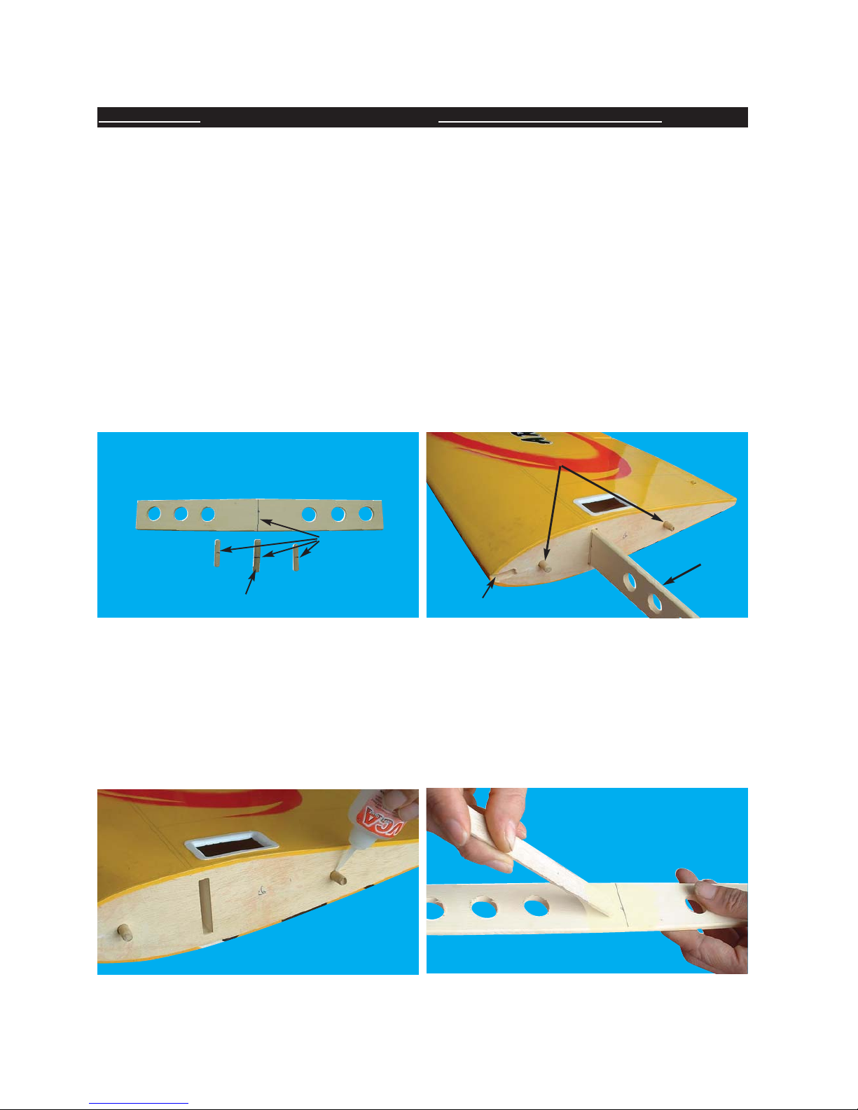
1.1 Locate the wing joiner (also called Dihedral brace). Using the ruler, determine the center of the wing joiner and
mark it with a pencil as illustrated in 1A. Also mark a center line on each of the dowel guides.
1A- Preparation of wing joiner and dowel guides. 1B- Trial fit the wing joiner and dowel guides
1.4 Apply plenty of 30 minute epoxy to one end of the wing joiner, using a stir stick or epoxy brush. Carefully insert
the joiner into the first wing panel as illustrated in 1D, 1E and 1F, then wipe off the excess epoxy that squeezes
out of the joint with a cloth or tissue. Repeat this process several times to ensure that the wing joiner and cavity
are well coated in epoxy. When the wing joiner & cavity are well coated with 30 minute epoxy, insert the joiner to
the center line, wipe away any excess epoxy and let dry. (Note: Do not use 5 minute epoxy or CA to join the wings)
1.2 Trial fit the wing joiner into the wing panels. It should insert smoothly up to the center line as illustrated in 1B.
Now slide the other wing panel onto the wing joiner until the wing panels meet. If the fit is overly tight, sand the wing
joiner slightly and try again.
1.3 Insert the dowel guides into one of the wing panels all the way to the center lines. Apply CA glue to secure the
dowels into their places as illustrated in 1B and 1C. Do not apply CA glue to the wing joiner.
1C- Apply CA glue to secure dowels into their places 1D- Apply plenty of epoxy glue to the wing
joiner.
wing joiner
dowel guides
Center line
Wing guide
Wing guide cavity
Page 3
3
2.1 When the epoxy has cured in Stage 1, trial fit the second wing
panel onto the wing joiner first to ensure that the two panels fit
without an excessive gap.
2.2 Now apply plenty of epoxy to the wing joiner and wing root ribs of
both wing panels. Use only 30 minute epoxy to ensure a strong bond
and give yourself plenty of working time. As described in the Step 1.4,
repeatedly apply epoxy and insert into the wing joiner cavity, the
epoxy should ooze from the joint and the excess should be cleaned
off with a rag or tissue before it cures.
2.3 Use low tack masking tape to hold the two panels together until
the glue cures.
1E- Carefully insert the joiner all the way to the cen-
ter line
2A- Apply plenty of 30 minute epoxy
glue to all surfaces.
2C- Use low tack masking tape to hold tightly
together.
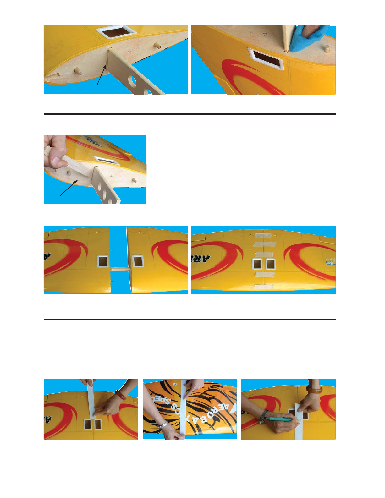
3.1 Once the epoxy has cured completely (allow several hours at least), the tape can be carefully removed from
the wing panels. Peel the tape back on itself… do not pull upright away from the wing. To seal and finish the joint
in the wings, a roll of wing joiner tape has been supplied.Starting on the bottom side of the wing, stick the tape centrally over the joint ensuring that it is pressed down firmly as you work around the wing. Wrap the tape all the way
around the wing joint in one piece, starting and finishing at the wiring harness cavities at the bottom of the wing.
Center line pointing up
1F - Wipe off the excess epoxy then allow to cure.
2B- Align the two wing panels and slowly close the
gap until the wing root ends are firmly in contact
with each other
3C- Trim off the excess tape.
3B- Continue applying the tape
over the bottom of the wing,
pressing down firmly as you go.
3A- Apply tape over the joint,
starting here
STAGE 2 - WING ASSEMBLY - JOINING THE WING HALVES CONTINUED.
STAGE 3 - WING ASSEMBLY - JOINING THE WING HALVES CONTINUED.
UP
Wing root
Page 4
4
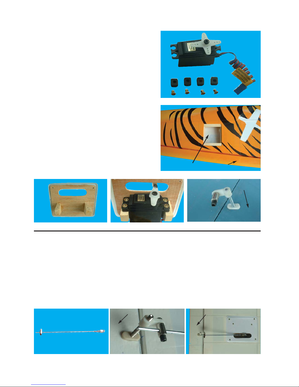
Aileron servo cavity
4B- Aileron servo location
4A- The servo componemts
STAGE 4
- INSTALLING THE AILERON SERVO INTO THE WING.
To install the aileron servo into the wing you will need the following items :
- 2 servos
- Servos mounting screws and grommets as supplied with servos.
- Servo control arms as supplied with the servos.
- Two aileron control rod assemblies supplied with the kit. The
assemblies consist of a metal rod with clevis screwed onto both
ends.
- Low tack masking tape.
- 2 aileron control horn assemblies
- 1 servo wire connection wire
STAGE 5 - INSTALLING AILERON CONTROL SYSTEM
5A- Aileron control rod assembly 5B- Aileron control horn assembly 5C- Aileron control installed
5.1 Consult your radio instruction manual and center the aileron servo by plugging it into the aileron channel in the
receiver. Turn on the transmitter and then the receiver. Center the aileron trim lever on the transmitter. Remove the
servo arm mounting screw and the servo arm.
5.2 Mount the servo arm back on the servo so that the arm is parallel with the back edge of the wing. Screw the
arm into place with the servo arm mounting screw supplied with the servo.
5.3 Locate the two aileron control rods in the hardware bag (see 5A). Ensure the clevises are screwed well onto
the threaded portion of the rod. Rotate and tug aggressively on the clevises and ensure that they are not loose on
the rods.
5.5 Ensure that the aileron control horns are screwed onto the threaded aileron control horn bolts and that both
control horns are in approximately the same place on their respective bolts.
Aileron
Aileron
Aileron
4.1 Carefully remove the white cover plates from the aileron
servo cavities. Ensure you know which cover plate is for the
right wing and which is for the left. Notice that there are wooden servo rails pre-installed into each servo cavity end.
4.2 Locate the wiring harness tubes that are protruding slightly
into each aileron servo cavity. The tube can be moved slightly
at this point. Check out the other end of each tube for a clean
position and then using C/A glue secure the wiring harness
tubes at the aileron servo cavity end.
4.3 Install a servo in each aileron servo cavity and connect the
servo wire to the servo extension wires and run the extension
wires through wiring harness tubes to the centre of the wing
Install the aileron control horns
4C- Aileron servos mount
4D- Screw servo in position
4E- Install aileron control horn
Aileron
Page 5
5
STAGE 6 - FITTING THE
HORIZONTAL AND VERTICAL
STABILIZERS
To install the stabilizers into the fuselage you will need.
- Fuselage
- Vertical stabilizer with pre-installed
rudder
- Horizontal stabilizer with preinstalled elevator
6A- The fuselage slots for the vertical & horizontal stabilizers
6B- Horizontal stabilizer with pre-installed elevator 6C- Vertical stabilizer with pre-installed rudder
Vertical slot
Horizontal slot
STAGE 7 - ALIGNMENT OF HORIZONTAL STABILIZER
7.1 Check the fit of the horizontal stabilizer in its slot. Make sure the
tail is square and centered to the fuselage by taking measurements
as shown in pictures 7A, 7B and 7C. Do not glue anything yet.
Equal
distance
Equal distance
90
0
7A- Trial fit the horizontal stabilizer in its
slot
7B- Alignment of horizontal stabilizer top view. 7C- Alignment back view
5.6 Connect the aileron servo rods to the aileron control horns.The one end with clevis will be attached to the servo
output arm.
5.7 Connect the other end of the rod to the control horn pre-installed with an EZ connector
5.8 Remove the masking tape holding the ailerons.
In the case of computer radios the servos together by connecting them to the appropriate receiver channel. In the
case of analog radios couple the servos together using a Y harness
5.10 Turn on your radio and activate the ailerons, using the aileron stick and ensure a smooth full motion can be
achieved.
5.11 With the wing top side up and viewed from the back, ensure that moving the transmitter aileron stick to the left
raises the left aileron and lowers the right aileron. Movement of the stick to the left will roll the aircraft to the left.
(Counterclockwise roll of the wing when viewed from the back ).
5.12 With the wing top side up and viewed from the back, ensure that moving the transmitter aileron stick to the
right raises the right aileron and lowers the left aileron. Movement of the stick to the right will roll the aircraft to the
right. (Clockwise roll of the wing when viewed from the back).
Page 6

6
8.1 With the horizontal stabilizer
aligned correctly, mark the shape of
the fuselage on the top & bottom of
the horizontal stabilizer using a
water soluble non-permanent felt-tip
pen as shown here
8A- Mark the top of the horizontal
stabilizer...
8B- ...and the bottom
STAGE 8
- INSTALLING
THE HORIZONTAL STABILIZER
9.1 Now remove the horizontal stabilizer & using a sharp
knife & a ruler CAREFULLY cut 1/8" (3 mm) inside the
marked lines & remove the covering on the top & bottom
of the horizontal stabilizer as illustrated. Make sure you
only cut the film & not the wood, otherwise the horizontal stabilizer will be severely weakened & fail.
9A- Marked lines on horizontal stab
9B- Cutting inside the lines
9C- Remove the covering from top surface.
9D- Exactly the same underneath 9E- Clean off the pen lines.
10A- Apply plenty of epoxy
10.1 Now apply sufficient epoxy to the top and bottom of
the horizontal stabilizer and horizontal slot. Use 30
minute epoxy to ensure a strong bond and give yourself
plenty of working time (see 10A & 10B).
10.2 Insert the horizontal stabilizer in its slot in the fuse-
lage and re-check the alignment as in Stage 7 (see 10C).
10.3 Excess epoxy should be cleaned off with a rag or
tissue before it cures (see 10D).
STAGE 9 - INSTALLING THE HORIZONTAL
STABILIZER CONTINUED
STAGE 10 - INSTALLING THE HORIZON-
TAL STABILIZER CONTINUED
Page 7

7
10B- Apply plenty of epoxy 10C- Slide the horizontal stabiliz-
er in place
10D- Wipe off excess epoxy
STAGE 11
- FITTING THE VERTICAL
STABILIZER
11.1 Check the fit of the vertical stabilizer in its slot.
Make sure that it is square to the horizontal stabilizer
and fuselage (see 11A)
11.2 Mark the shape of the fuselage on the left & right
sides of the vertical stabilizer using a felt-tip pen (11B)
11.3 Now remove the vertical stabilizer, using a sharp
knife & ruler, CAREFULLY cut just 1/8" (3mm) inside
the marked lines (see 11C) and remove the covering
on both sides of the fin (see 11D), just as you did with
the horizontal stabilizer, making sure you only press
hard enough to cut the covering, not the vertical stabi-
lizer. Do not cut the wood.
11A- Trial fit the vertical stabilizer into fuselage slot.
11B- Mark both sides of the verti-
cal stabilizer
11C- Carefully cut through the
covering
11D- Remove covering from both
sides
12.1 Now apply sufficient epoxy to both sides & the bot-
tom of the vertical stabilizer as illustrated in 12A. Use 30
minute epoxy to ensure a strong bond and give yourself
plenty of working time.
12.2 Insert the vertical stabilizer in its slot in the fuse-
lage and re-check the alignment. Excess adhesive
should be cleaned off with a rag or tissue before it
cures.
12A- Apply plenty of epoxy 12B- Slide the stab into place &
remove excess epoxy
12C- 90 degrees angle between
the horizontal and vertical stabs.
90
0
STAGE 12 - FITTING THE VERTICAL STABILIZER CONTINUED
Page 8

8
Identify the main landing gear components shown below
- 2 main landing gear esemblies
- 2 main wheels 2-7/16” ( 60mm)
- 8 sheet metal screws and 4 straps
- 2 wheel collars
13A- Main landing gear components
13B- Turn over the wing to locate
the pre-drilled main landing gear
mounting holes.
13C- Main landing gear assembly
13D- Use 4 sheet metal screws
and 2 traps to mount the main
landing gear into the wing
Pre-made main-landing
gear mounts
STAGE 13
- FITTING THE MAIN LANDING GEAR
2 main landing
gear esemblies
Wheels
Wheel collars
Landing gear straps
Metal screws
Wheel collars
STAGE 14 - FITTING THE TAIL WHEEL
14A- Tail wheel components
14B- Slide the tail wheel asembly
into the pre-installed sleeve tube
14C- Screw the tail wheel assem-
bly to the fuselage
14D- Trim off the excess tail
steering wire
Identify the tail wheel components
- 1 tail gear esembly
- 2 (3 x 15 mm) sheet metal screw
14.1 Slide the loose wire end on the tail wheel asembly
into the sleeve tube that has been installed into bottom
of the rudder.
14.2 Position the plastic bracket on the bottom of the
fuselage. Mark the location of the screw holes. Tap the
holes with the screws and then fasten the plastic bracket to the fuselage. See 14C & 14D
Page 9

9
Engines vary quite a bit in sizes, styles and brands but
most have mounting lugs, a carburetor with a throttle
(speed) control arm, a prop washer, a prop nut and a
muffler.
The procedure we describe here assumes that you are
mounting a 2-stroke engine that has a side exhaust on
the right (when viewed from behind looking forward)
and a throttle control arm on the right.
To assemble the fuel tank you will need the following
items:
- The fuel tank and fuel stopper assembly (supplied)
- The clunk (supplied)
- About 7” (20 cm) of medium ID silicone fuel line (DUB
197 or DUB-222 or similar)
- Cross head Phillips screw driver
15C - Illustration of fuel line positioning inside cutaway of the tank
15D - Fuel tank installed into the
fuselage
fuel line
pressure line
fuel line
pressure line
15B - Use 4" (100 mm) for fuel line
and 2" (50mm) for pressure line
4” (100mm) for fuel line
2” (50mm) for pressure line
16A- VMAX 46PRO 2 cycle engine recommended
16C- Remove the muffler, position the engine on
the engine mount and confirm that the fuel tank
metal tubes clear the back of the engine. Trial fit
the engine temporarily into place. Tighten the
screws only enough to tack the engine into place
16B- Use a 4mm socket ball wrench or Allen Key
to remove the 4 black machine screws that work
with the clamping plates on the metal engine
mount that has been pre-installed into your
Hornet
STAGE 15
- FITTING THE FUEL TANK
15A - Fuel tank & stopper assembly.
STAGE 16
- INSTALLING THE ENGINE
Connect to the fuel line
fuel line
Connect to the
presure line
pressure line
throttle control rod
Clamping plates
Machine screws
fuel line pressure line
Page 10

10
17B- Throttle control rod connected to the engine throttle arm
and to the servo arm
17A- Clevis attached to engine
throttle arm
18A- Fuel line connected to the car-
buretor and pressure line connect-
ed to the muffler.
STAGE 18
- CONNECTING THE FUEL & PRESSURE LINES
18.1 Install the muffler then connect the fuel tubing from the
tank metal pressure lines to the muffler
18.2 Connect the fuel tubing from the tank metal fuel line to the
carburetor
18.3 Double check that you have the metal fuel line from the
tank connected to the carburetor and that the metal pressure
line from the tank to the muffler.
STAGE 19 - INSTALL THE PROPELLER AND THE SPINNER
19.1 Consult your engine manual and select a suitable propeller.
19.2 Install the thrust washer, the spinner backing plate, the pro-
peller, the prop washer, and the prop nut. Ensure that they are all
firmly attached.
19.3 Trial fit the spinner cone and spinner cone retaining screws. If
necessary enlarge the cutouts in the spinner cone to allow adequate clearance for the propeller. The spinner should not touch the
edges of the propeller.
19.4 Double check that the spinner cone retaining screws are firmly attached.
19A- The spinner and propeller
attached to the engine.
STAGE 20 - FITTING ELEVATOR AND RUDDER CONTROL HORN
20.1 The elevator control horn
is installed through the elevator and protrudes from the bottom of the elevator as shown in
20A and 20B. Pierce the covering over the pre-drilled hole
and install the control horns as
shown.
20A- Control horn assembly
20B- Typical control horn mounted
to the surface control
STAGE 17
- CONNECTING THE THROTTLE CONTROL ROD TO THE ENGINE.
Page 11

11
21.1 Install the rubber servo grommets & brass ferrules supplied
with your radio equipment. The three servos that control the elevator, rudder and throttle are to be installed in the servo tray mounted
in the fuselage. Remove the servo tray from the fuselage, mounting
the servos to the servo tray as shown.
21A- Universal servo tray
20C- Elevator control horn location
20D- Rudder control horn location
Elevator
control
horn
location
Rudder
control
horn
location
21B- Note the orientation and positions of the three
servos in the servo tray
21C- Throttle, rudder and elevator servos connected to their push rods as referenced left to right.
22.1 Consult illustrations 21C & 22A-C showing how the throttle, rudder and elevator servos are positioned and connected to the
pushrods.
STAGE 21
- INSTALLING THE SERVOS
STAGE 22 - CONNECTING THE PUSHRODS
TO THE THROTTLE, RUDDER AND ELEVATOR SERVOS
22A- Throttle (left), elevator (upper) & rudder (lower)
servos connected to their respective push rods.
Throttle
servo
Elevator
servo
Rudder
servo
NOSE TAIL
NOSE TAIL
Page 12

12
23.1 Connect the elevator servo to the receiver and turn on your transmitter. Confirm that
the neutral positions of the elevator servo are sustained as per illustration 22C
22B- Pre-installed elevator, throttle and rudder
pushrod
22C- Center the servos, control surfaces & throttle
(carb) then connect the control rods to the servos.
23A- elevator control horns
shown in position
23B-
Loosen the set screws to connect the elevator pushrods to the elevator control horns, align the elevator surfaces so that it is level with the
plane of the horizontal stabilizer, then tighten set screws securely.
24.1 Connect the rudder servo to the
receiver & turn on your transmitter.
Confirm that the neutral position of
rudder servo is sustained as per illustration 22C
24A - The rudder pushrod is connected to the rudder control horn
25.1 With the throttle control arm clevis connected to the engine throttle
arm, move the throttle arm to roughly half throttle. Look into the throat of
the engine carburetor as you rotate the throttle arm and select a position
where the throttle opening is about haft what it is when fully open.
25A- Throttle control rod connected to the engine throttle arm and
to the servo arm
Connected to the engine throttle arm
engine throttle arm
25B- Throttle control rod connected to the engine throttle arm
Elevator pushrod
Throttle pushrod
Rudder pushrod
STAGE 23
- CONNECTING THE PUSHRODS TO THE ELEVATOR
STAGE 24 - CONNECTING THE PUSHRODS TO THE RUDDER
STAGE 25
- CONNECTING THE THROTTLE CONTROL
NOSE TAIL
NOSE TAIL
Page 13

13
26.1 Adjust the deflection of the control surfaces to match the specifications on page 15
You can reduce the amount of throw by doing either or both of the following:
- From the servo end, move the clevis or EZ connector to a hole in the servo arm that is closer to the servo output
shaft.
- From the control horn end, move the horn out further on the threaded bolts. Always confirm that the horn is still
thoroughly engaged with the threaded bolt after you have adjusted it.
Before starting the final
set-up of the model,
switch on the radio and
ensure that all trims are
in their neutral positions. Check that the
ailerons, elevator and
rudder are centered. If
any adjustments are
needed, do these by
uncoupling the relevant
clevis and turning it
clockwise to shorten
the linkage or counter clockwise to lengthen it.
Only when each control
surface has been centered mechanically in
this way should you
begin adjusting the surface movement (or
throw)
Now confirm
that the control surfaces
are moving
in the correct
direction.
Use the
servo reversing switches
on your
transmitter to
reverse the
direction of a
servo if necessary. The
most popular
transmitter
mode (with
the throttle
on the left,
with ailerons
and elevator
on the right)
is shown
here.
STAGE 28
ELEVATOR
UP
ELEVATOR
DOWN
AILERON
UP
AILERON
DOWN
AILERON
DOWN
AILERON
UP
RUDDER
RIGHT
RUDDER
LEFT
STAGE 26
- ADJUST CONTROL SURFACE THROW LIMITS
STAGE 27
FINAL RC SET-UP
Page 14

14
STAGE 29
- INSTALLING THE RECEIVER BATTERY
STAGE 30 - INSTALLING THE RECEIVER
29.1 Consult your radio manual for instructions about hooking up your receiver battery, receiver and switch har-
ness.
29.2 Wrap the battery pack securely in foam suitable for RC equipment and wrap the foam insulated pack in a
plastic bag or cling wrap. Position the battery pack under the fuel tank or nearby.
29.3 Thread the battery pack connector back through from beneath the fuel tank to the radio compartment by
passing the battery connector through an opening beside or beneath the fuel tank.
29.4 Connect the battery connector to your radio system according to the radio manual.
30.1 Consult your radio manual for instructions about hooking up your receiver.
30.2 Plan where you are going to put the receiver with consideration for routing the antenna safely.
30.3 Wrap the receiver securely in foam suitable for RC equipment and wrap the foam insulated receiver in a
plastic bag or cling wrap.
30.4 Generally in the absence of specific instructions from the radio manufacturer, it is recommended that the
receiver should be placed where it is least likely to have impact during a crash. Keep the battery pack and other
heavy loose items ahead of the receiver.
STAGE 31 - CONFIRM RADIO OPERATION
STAGE 32 - BALANCING THE AIRCRAFT
31.1 Consult your radio manual for instructions about testing and operating your radio system.
31.2 Pay particular attention to charging your radio system batteries and range testing the system before and
after each flight.
31.3 Check that all controls are working correctly before and after each flight.
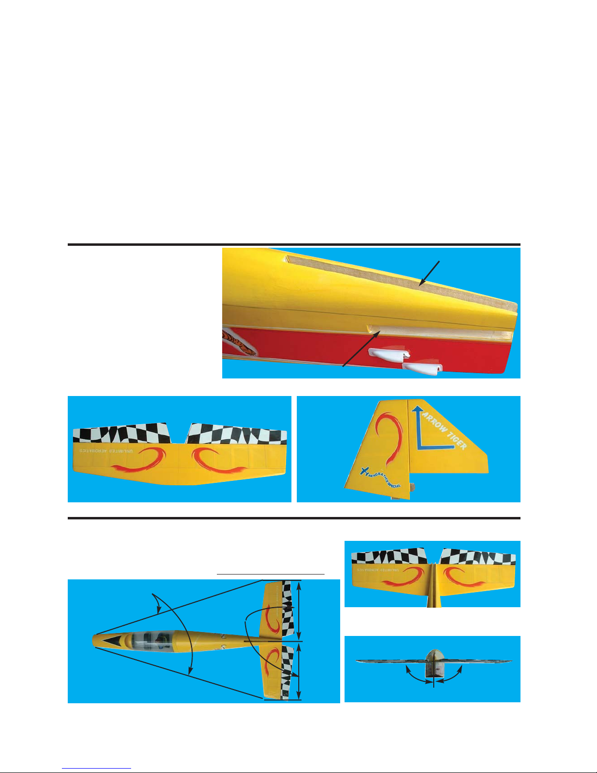
32.1 The CG for your HORNET is located at 3-1/8“ to 3-3/8" (80 - 85 mm) back from the leading edge of the wing
when the wing has been attached to the fuselage as per illustration 34A.
32.2 For the initial flight, the CG should be located at 3 1/8” (80mm) back from the leading edge of the wing
when the wing has been attached to the fuselage.
32.3 The CG is measured with the engine, radio gear and all other components installed but WITH NO FUEL IN
THE TANK.
32.4 Set up the CG as it will be when you fly it BUT WITH NO FUEL IN THE TANK.
32.5 It is very important to have the CG correct. Flying your model with the CG too far will likely lead to loss of
control and a crash.
If you discover that after you have assembled your model and installed your radio and engine that the CG of your
model is incorrect you must bring the CG to the correct location by doing the following BEFORE FLYING :
- Move the battery pack fore or aft.
- Move other components fore or aft.
- Change engine to a lighter or heavier model.
- Add weight to the nose or tail. If adding it to the nose, try to make it useful by going to a heavier duty engine
or adding a spinner with a heavy metal backing plate. As a last resort, add stick on “dead” weight where appropriate.
Page 15

15
33.1 Once you have confirmed that the CG is correct,
you should do a thorough review of the entire model
before your first flight. Check everything twice! Every
hook up, every coupling, everything! Do it twice!!
33.2 Before your first flight, have an experienced flyer
review your work. Do not fly your model until it has
been checked out by a third party who knows how to
fly and how to set up a model aircraft. Do not fly alone.
Seek experienced help.
33.3 Once you have completed your first flight, get in
the habit of checking your model over before and after
each flight! Don’t fly if you find something that is not
right!
80 - 85 mm
3 1/8 - 3 3/8”
Elevator
Aileron Rudder
CG
STAGE 33
- CONFIRM MECHANICAL INTEGRITY
33A- CG location
CONTROL SURFACE THROW SPECIFICATIONS: The throws are measured at the widest part of the control
surface. Adjust the position of the pushrods at the control and/or servo horns to control the amount of throw.
You may also use ATV's if you radio has them but the mechanical linkages should still be set so that the ATV's
are near 100% for best servo resolution.
5/8”-1”
16mm - 25mm
1/4”-3/8”
6mm - 9mm
1/3”-1/2”
8mm - 12mm
Low rate High rate
ELEVATOR 1/3 “ (8mm) up 1/2” (12 mm) up
1/3 “ (8mm) down 1/2” (12 mm) down
AILERON 1/4” (6 mm) right 3/8” (9 mm) right
1/4” (6 mm) left 3/8” (9 mm) left
RUDDER 5/8 “ (16 mm) up 1” (25 mm) up
5/8 “ (16 mm) down 1” (25 mm) down
5/8”-1”
16mm - 25mm
1/4”-3/8”
6mm - 9mm
1/3”-1/2”
8mm - 12mm
Page 16

16
Parts for this VMAR Model
In the event that you require replacement parts for your ARROW TIGER 40-52 ARF, you can order parts from
your retailer or from the VMAR On - line store at www.richmondrc.com/support.htm.
For aftermarket parts and other information related to this model see the VMAR On - Line store at
www.richmondrc.com/support.htm
VMAR, POLYCOTE and VMAX are Trademarks of VMAR Manufacturing Inc. and appointed VMAR agents worldwide.
Copyright VMAR Manufacturing Inc - 20032809
The Graphics and Detailing are inside the POLYCOTE ECS!
TM
ARROW-Tiger
 Loading...