

Page 1
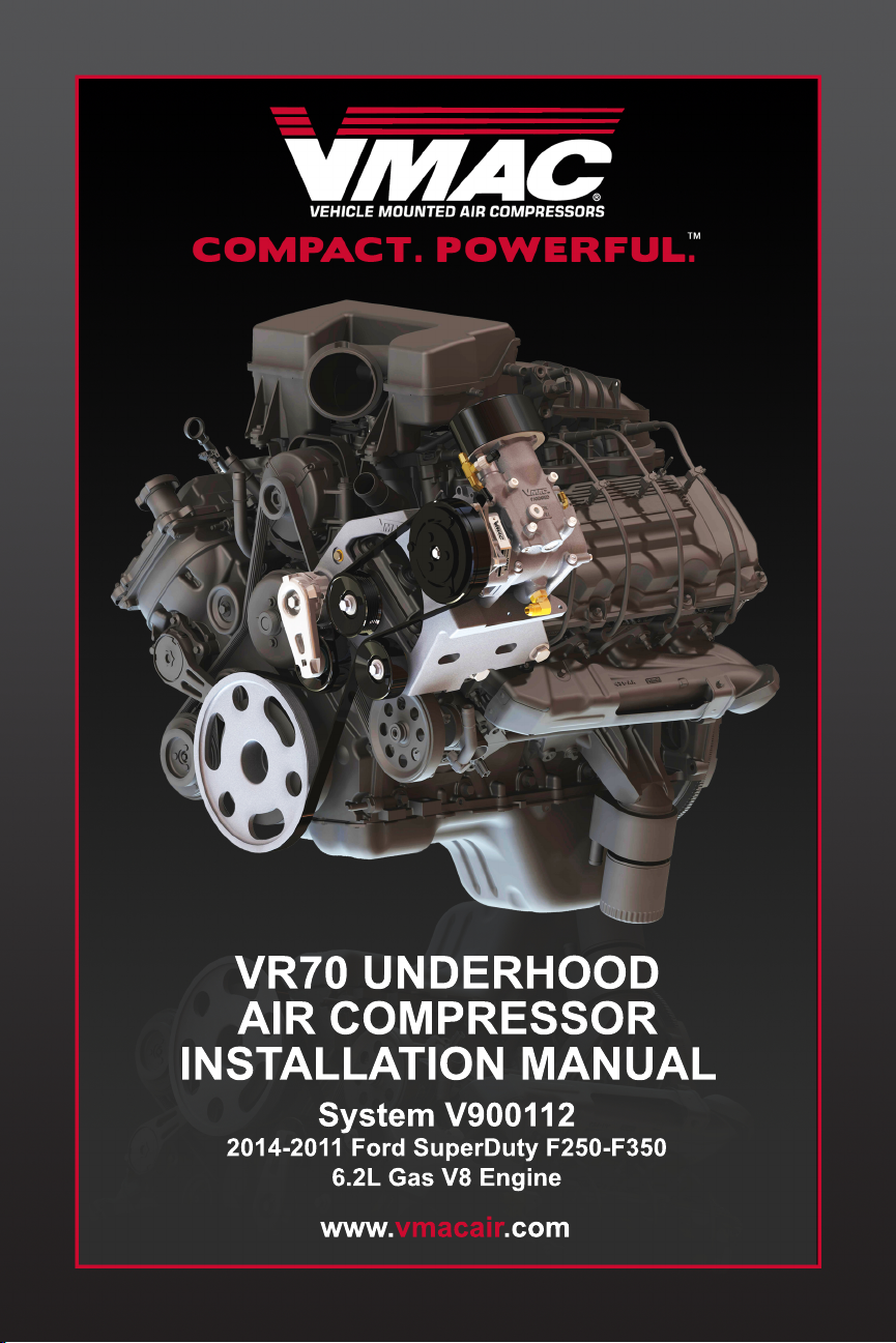
VR70 UNDERHOOD
AIR COMPRESSOR
INSTALLATION MANUAL
System V900112
2014-2011 Ford SuperDuty F250-F350
6.2L Gas V8 Engine
www.vmacair.com
Page 2

Page 3

VMAC – Vehicle Mounted Air Compressors
Toll Free: 1-888-241-2289
Fax: 1-250-740-3201
1
Installation Manual for VMAC
System V900112
2014-2011 Ford SuperDuty F250-F350
6.2L Gas V8 Engine
General Information ........................................................................ 4
Before You Start ........................................................................... 4
Additional Requirements .............................................................. 4
Part 1: Warranty and System ID ..................................................... 5
Part 2: Preparing for Installation .................................................. 8
Part 3: Installing the Main Bracket, Compressor & Cooler ........ 15
3.1 Installing the Main Bracket and Compressor ......................... 15
3.2 Installing Drive Belts and Pulleys ........................................... 19
3.3 Installing Other Components ................................................. 20
3.4 Installing the Cooler ............................................................... 23
Part 4: Installing the Tank and Hoses .......................................... 28
4.1 Installing the Tank and Mount Brackets ................................. 28
4.2 Installing the Hoses ................................................................ 31
4.3 Adding Oil to the System ....................................................... 33
Part 5: Installing the Control Components .................................. 34
5.1 Installing the Components ..................................................... 35
5.2 Connecting the In-cab Wiring ................................................. 35
5.3 Connecting the Underhood Wiring ......................................... 36
Part 6: Finishing the Installation .................................................... 37
6.1 Reinstall OEM components. .................................................. 37
6.2 Before Starting the Engine Checklist ..................................... 39
6.3 Safety Test ............................................................................. 40
6.4 After Starting the Engine Checklist ........................................ 41
6.5 Setup, Performance Testing and Adjustments ...................... 42
6.6 Auxiliary Air Receiver ............................................................. 43
Accessory Products from VMAC ................................................... 44
Page 4
VMAC – Vehicle Mounted Air Compressors
Toll Free: 1-800-738-8622
Fax: 1-250-740-3201
2
!
Document #1930169
Installation Manual for VMAC System V900112
Ford 2014 - 2011 6.2L Gas V8 Superduty F250-F350
Changes and Revisions
Version
Revision Details
Revised by/date
Checked by/date
Reviewed by/date
Implemented
F
ECN 12-127, 12-148
SAR 10 Sep 2012
MH 15 Oct 2012
N/A
16 Oct 2012
G
ECN 12-157
SAR 29 Oct 2012
MH 13 Nov 2012
N/A
14 Nov 2012
H
ECN 13-013, 14-006
JR 19 Feb 2014
MH 13 Mar 2014
RD 20 Mar 2014
24 Mar 2014
J
ECN 15-084
RR 28 Jul 2015
CH 28 July 2015
GB 28 July 2015
28 July 2015
K
ECN 17-131
MSP 27Jul 2017
CM 03 Aug2017
AMG 09 Aug 2017
10 Aug 2017
Important Information
This symbol is used to call your attention to instructions
concerning your personal safety. Watch for this symbol; it
points out important safety precautions, it means “attention,
become alert! Your personal safety is involved. Read the
message that follows and be alert to the possibility of personal
injury or death. Be alert; your safety is involved. While it is
impossible to warn about every conceivable hazard, let good
common sense be your guide.
This symbol is used to call your attention to additional
instructions or special emphasis on a specific procedure.
The information in this manual is intended for certified VMAC
installers who have been trained in installation procedures and for
people with mechanical trade certification who have the tools and
equipment to properly and safely perform the installation. Do not
attempt this installation if you do not have the appropriate
mechanical training, knowledge and experience.
Follow all safety precautions for underhood mechanical work. Any
grinding, bending or restructuring operations for correct fit in
modified trucks must follow standard shop practices.
All hoses, tubes, and wires that are rerouted or shifted
during installation must be secure so that they do not
contact excessively hot areas or sharp edges. Where
possible, use rubber coated P-clips. Follow the routing
suggestions in this manual and cover all hoses with
the supplied plastic loom.
These instructions are a general guide for installing this system on
standard production trucks and do not contain information for
installation on non-standard trucks. This system may not fit special
order models or those which have had other changes without
additional modifications. If you have difficulty with the installation,
contact VMAC.
!
Page 5

VMAC – Vehicle Mounted Air Compressors
Toll Free: 1-888-241-2289
Fax: 1-250-740-3201
3
The VMAC warranty form is located at the back of this manual.
This warranty form must be completed and mailed or faxed to
VMAC at the time of installation for any subsequent warranty claim
to be considered valid.
To order parts, contact your VMAC dealer. Your dealer will ask for
the VMAC serial number, part number, description and quantity.
To locate your nearest dealer, call 1-888-241-2289.
Copyright 2017
All trademarks used in this manual are the property of the respective
copyright holder.
The contents of this manual may not be reproduced in any form without
the express written permission of VMAC, 1333 Kipp Road, Nanaimo, BC
V9X 1R3.
Printed in Canada
Page 6
VMAC – Vehicle Mounted Air Compressors
Toll Free: 1-800-738-8622
Fax: 1-250-740-3201
4
General Information
Before You Start
Read this manual before attempting installation so that you can
familiarize yourself with the components and how they fit on the
truck. Identify variations for different model years and different
situations that are listed in the manual. Open the package, unpack
the components and identify them.
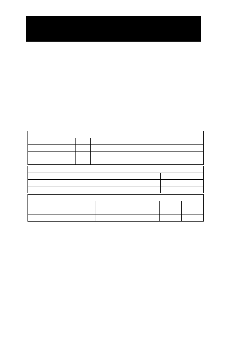
All fasteners must be torqued to specifications. Use manufacturers
torque values for OEM fasteners. Apply Loctite 242 or equivalent
on all engine-mounted fasteners. Torque values are with Loctite
applied unless otherwise specified.
STANDARD GRADE 8 NATIONAL COARSE THREAD
Size
1/4
5/16
3/8
7/16
1/2
9/16
5/8 ¾ Foot-pounds (ft-lb)
9
18
35
55
80
110
170
280
Newton meter
(N•m)
12
24
47
74
108
149
230
379
STANDARD GRADE 8 NATIONAL FINE THREAD
Size
3/8
7/16
1/2
5/8 ¾ Foot-pounds (ft-lb)
40
60
90
180
320
Newton meter (N•m)
54
81
122
244
434 METRIC CLASS 10.9
Size
M8
M10
M12
M14
M16
Foot-pounds (ft-lb)
19
41
69
104
174
Newton meter (N•m)
25
55
93
141
236
Additional Requirements
Special Tools
Pneumatic fan wrench removal set (such as Lisle 43300) or a
manual fan pulley holder (such as KD3900)
OEM flywheel locking tool part number J42386.
Hose Information
Different frame designations will affect the tank mounting position.
If you have to move the tank, the lines may be too short. Measure
the hose shortfall and order a Hose Extender Kit.
Page 7

VMAC – Vehicle Mounted Air Compressors
Toll Free: 1-888-241-2289
Fax: 1-250-740-3201
5
Part 1: Warranty and System ID
□ Complete the warranty form. The VMAC warranty form is
located at the back of this manual. This warranty form must be
completed and mailed or faxed to VMAC at the time of
installation for any subsequent warranty claim to be
considered valid.
System Identification and Operating Instructions
The System Identification Number Plate must be attached to the
vehicle at the time of installation. This plate provides information
that allows VMAC to assist in customer inquiries and the ordering
of parts.
□ Mark and drill two 7/64-inch holes in the top of the cross
member between the driver's side headlight and the air filter
box then secure the plate with self-tapping screws.
□ Affix the VMAC belt routing diagram to an appropriate place
near the OEM belt diagram.
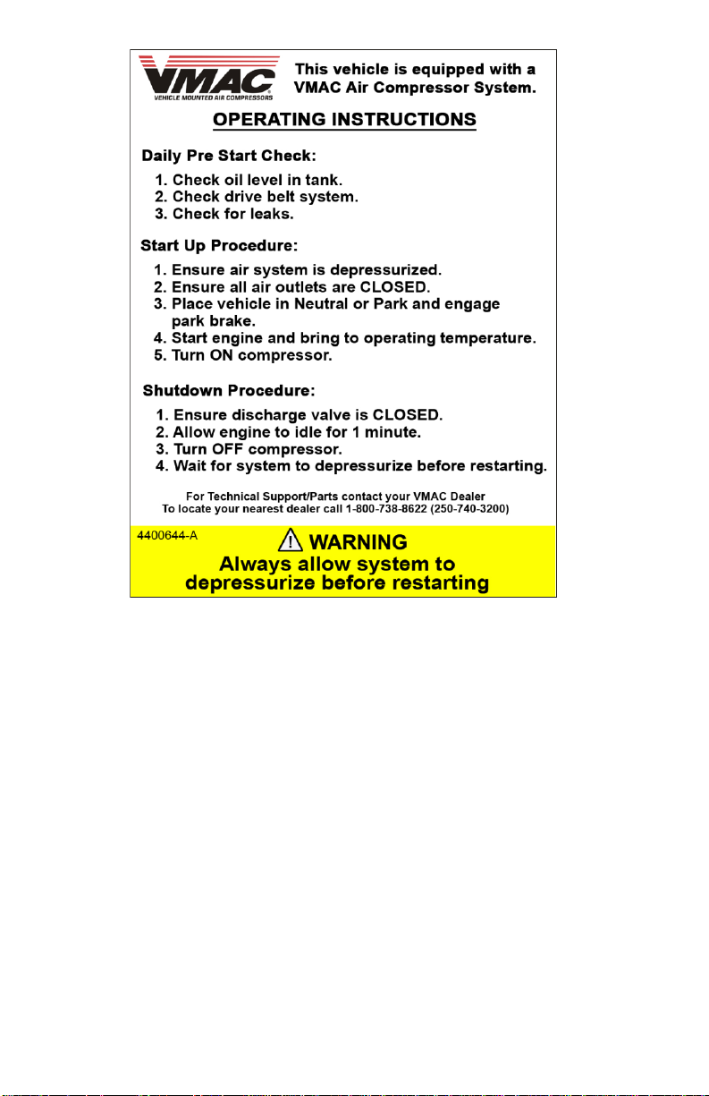
□ As part of the installation process, ensure that the safety and
operational instruction decal is affixed in an obvious location
so that it can be seen by vehicle operators. A good spot for
this is usually on the inside of the door or on the panel
underneath the steering wheel. (Figure 1.1).
Page 8
VMAC – Vehicle Mounted Air Compressors
Toll Free: 1-800-738-8622
Fax: 1-250-740-3201
6
Figure 1.1
Page 9
VMAC – Vehicle Mounted Air Compressors
Toll Free: 1-888-241-2289
Fax: 1-250-740-3201
7
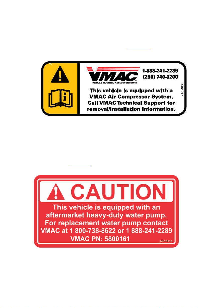
□ To alert any technicians that may service the vehicle, affix the
servicing caution/contact label in the engine compartment near
the hood latch in a visible location. Thoroughly clean the
selected area before affixing the label (Figure 1.2)
Figure 1.2
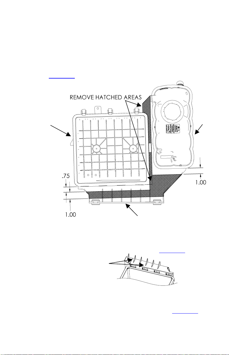
□ As part of the installation process, ensure that the caution
decal regarding the heavy duty water pump is affixed in an
obvious location so that it can be seen by maintenance
personnel. (Figure 1.3)
Figure 1.3
Page 10

VMAC – Vehicle Mounted Air Compressors
Toll Free: 1-800-738-8622
Fax: 1-250-740-3201
8
Part 2: Preparing for Installation
Preparation for installation is very important. Missing an item can
cause problems in the installation or even damage to components.
Check off each item as it is completed so that you do not miss any
preparation steps.
□ Locate the blunt-cut OEM SEIC wire harness, on the driver’s
side just below the OBDII port. You will need to find the
transmission park signal (blue with grey stripe wire).
□ Use a multi-meter to verify the transmission park signal. Turn
the key to the IGN2 position (do not start the truck), as to
supply power to the dash display. The resistance should read
close to 0-ohms in park and open circuit in all other gears. If
this is correct, put the car in park and turn the key to the off
position.
There are multiple blue wires with various coloured
stripes. The transmission park signal needs to be
electrically verified with a multi-meter to ensure the
correct wire is read.
□ Mark transmission park signal wire for connection later in
installing control components section
□ Disconnect the battery.
□ Drain the coolant.
□ Remove the air filter box cover, filter, and intake tube from the
truck.
□ Remove the power steering reservoir from the driver's side of
the fan shroud keeping all the lines connected. Temporarily tie
the reservoir up and out of the way of the shroud. Note: The
cap will leak if the reservoir is not kept upright.
Page 11
VMAC – Vehicle Mounted Air Compressors
Toll Free: 1-888-241-2289
Fax: 1-250-740-3201
9
□ Remove the vacuum pump and tank from the passenger side
of the fan shroud (if equipped).
□ Remove the upper radiator hose.
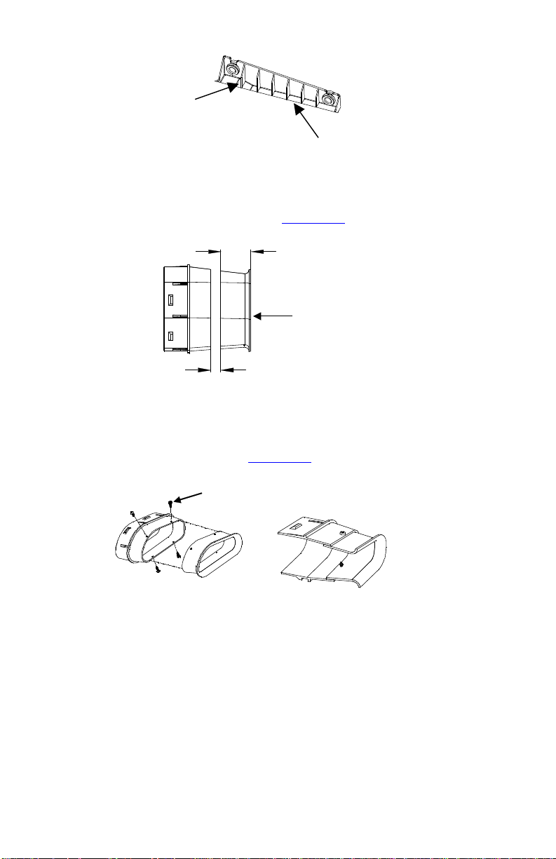
□ Remove the air filter box and coolant degas bottle assembly
from the truck. Cut the assembly into three pieces as shown in
(Figure 2.1).
Air Box Mount
Air Box
Degas
Bottle
Figure 2.1
□ Cut away the webbing on the top of the air box (Figure 2.2).
Remove all webbing on
top of Air Box
Figure 2.2
□ Cut away all of the webbing on the bottom of the air box mount. Do
not remove the webbing on top of the air box mount (Figure 2.3).
Page 12
VMAC – Vehicle Mounted Air Compressors
Toll Free: 1-800-738-8622
Fax: 1-250-740-3201
10
Remove all webbing on
bottom of Air Box mount
Leave webbing on top of
Air Box mount
Figure 2.3
□ Measure 2-1/4” back from the front edge of the air intake horn and
cut ¾” and discard the cut section (Figure 2.4)
2-1/4”
3/4”
Air Intake
Horn
Figure 2.4
□ Reattach the two cut air horn pieces. Overlap the two pieces by ½”
and drill pilot holes. Using the supplied self-tapping screws reassemble the air intake horn (Figure 2.5).
Re-assembled Air
Intake Horn
Self-Tapping
Screws
Figure 2.5
□ Remove the upper and lower bolts locating the upper fan shroud
and remove the coolant overflow hose from the upper fan shroud.
□ Unbolt and disconnect the fan wire harness from the fan shroud.
□ Unclip the large wire bundle and radiator hose from the bottom of
the fan shroud.
Page 13
VMAC – Vehicle Mounted Air Compressors
Toll Free: 1-888-241-2289
Fax: 1-250-740-3201
11
□ Swing the lower fan shroud section forward and lock it in place.
□ Remove the fan (right-hand thread) and pull it out of the engine
bay with the shroud.
For ease of fan removal and installation, it is
recommended that a pneumatic fan wrench removal set
(such as Lisle 43300) or a manual fan pulley holder (such
as KD3900) is used.
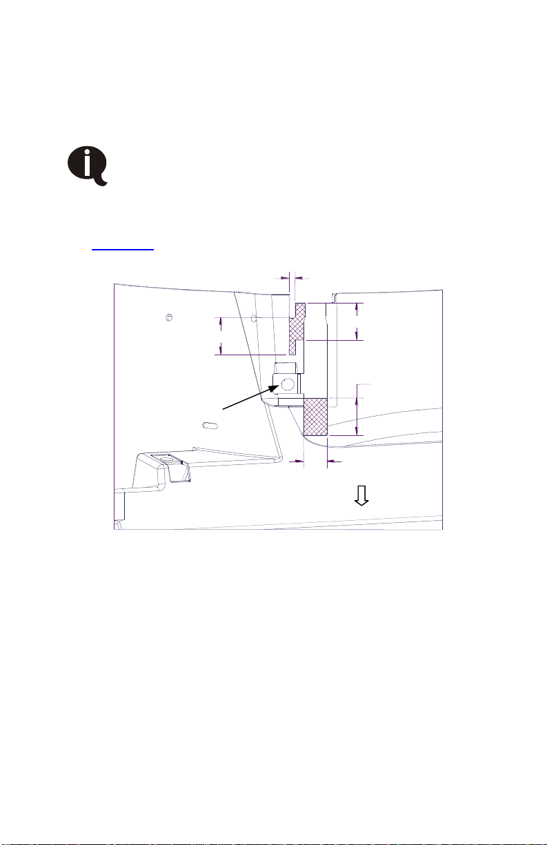
□ Modify the fan shroud by cutting away the hatched area shown.
(Figure 2.6)
1 3/8”
1 3/8”
1 3/8”
Fan Wiring Connector
Bracket OEM Mount
Location
Front
7/8”
1/4"
Figure 2.6
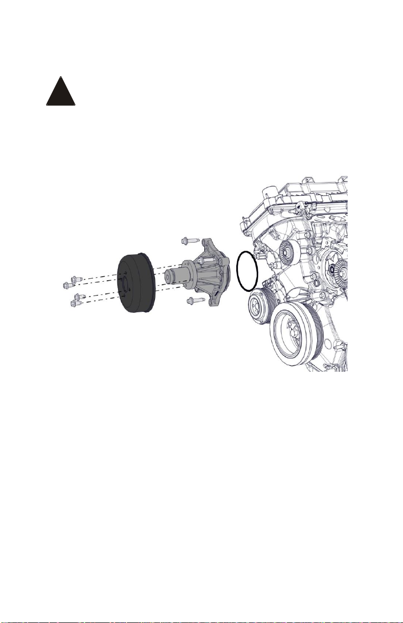
□ Loosen the 4 coolant pump pulley bolts, Refer to Figure 2.7.
□ Remove the accessory drive belt.
□ Remove the 4 pulley bolts, and the coolant pump pulley.
□ Remove the 4 pump bolts and the coolant pump.
Page 14
VMAC – Vehicle Mounted Air Compressors
Toll Free: 1-800-738-8622
Fax: 1-250-740-3201
12
□ Inspect and clean sealing surfaces.
Before installing the supplied coolant pump, align the
bolt holes prior to inserting the coolant pump and
insert the coolant pump straight into the coolant pump
cavity. Do not rotate the coolant pump once installed
in the coolant pump cavity or damage to the O-ring
may result, causing the pump to leak coolant.
Figure 2.7
□ Lubricate the O-ring on the supplied pump with clean engine
coolant.
□ Install the supplied coolant pump, reuse OEM bolts. Tighten the 4
bolts in a criss-cross pattern in 3 stages:
o Stage 1: finger-tighten the bolts.
o Stage 2: Tighten to 20 Nm (15 ft-lb)
o Stage 3: Tighten an additional 45 degrees.
□ Install the coolant pump pulley and 4 bolts.
□ Install the accessory drive belt.
!
Page 15
VMAC – Vehicle Mounted Air Compressors
Toll Free: 1-888-241-2289
Fax: 1-250-740-3201
13
□ Tighten the 4 bolts for the coolant pump pulley to 25 Nm
(18 ft-lb.).
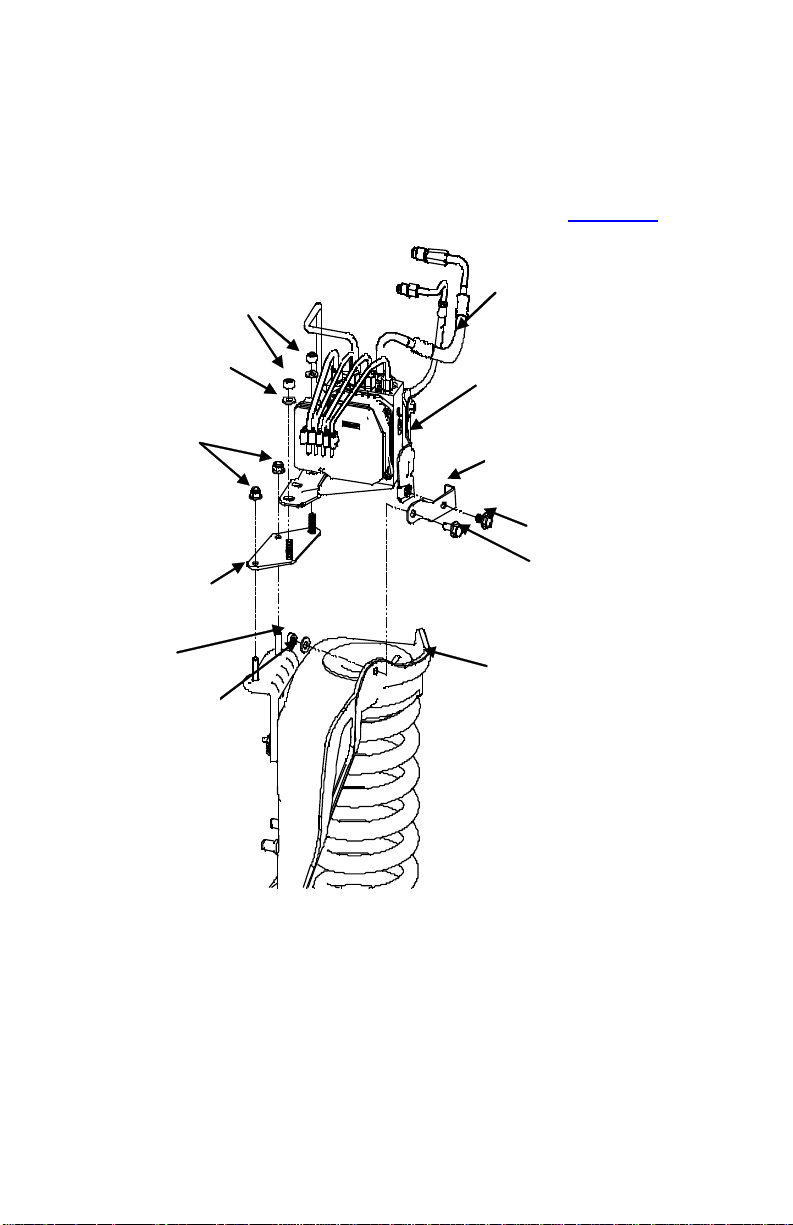
□ Remove the bolt and two nuts securing the ABS hydraulic control
unit (HCU) module to the driver's side suspension tower and install
the two supplied relocation brackets as shown in (Figure 2.8).
M8 Nut
ABS HCU Module
ABS HCU Bracket
Driver Side Suspension
Tower
ABS HCU Bracket
OEM Nuts
M8 Nuts
5/16 Washers
M8 x 16 Bolts
OEM Bolt
5/16 Washer
Rotate The Flexible Brake
Lines To Avoid Kinking
Figure 2.8
Page 16

VMAC – Vehicle Mounted Air Compressors
Toll Free: 1-800-738-8622
Fax: 1-250-740-3201
14
□ It may be necessary to rotate the brake lines that connect the
master cylinder to the ABS HCU module to avoid kinking the
flexible rubber hoses. To do this, have a helper press gently on
the brake pedal as you reposition the brake lines. This will help
avoid air entering the brake system due to brake fluid being forced
out rather than air let in. Do not pump the brakes at any time while
the brake lines are loose or air may be drawn into the system.
If you are at all concerned that air has entered the brake
system consult your local Ford dealer or repair shop for
truck specific HCU brake bleeding instructions.
Loosen the brake lines one at a time just enough to rotate them
into a relaxed and kink-free position, then quickly tighten them
while constant pedal pressure is being applied. If a significant
amount of fluid escapes from the fittings, the pedal is being
pressed too hard and/or the fitting has been loosened too much.
Do not allow the brake master cylinder to run dry during
these steps as the master cylinder may be damaged if
operated without fluid.
Be sure to wipe up any fluid as soon as possible as it can damage
painted and plastic surfaces. After wiping up any fluid, rinse the
area with water. Ensure that the fluid reservoir is topped when
finished.
Do not use any fluid other than clean brake fluid from an
unopened container that meets Ford specifications.
If you do not follow these instructions you risk system
contamination, brake component damage and serious
personal injury.
! ! !
!
Page 17
VMAC – Vehicle Mounted Air Compressors
Toll Free: 1-888-241-2289
Fax: 1-250-740-3201
15
Part 3: Installing the Main
Bracket, Compressor & Cooler
3.1 Installing the Main Bracket and Compressor
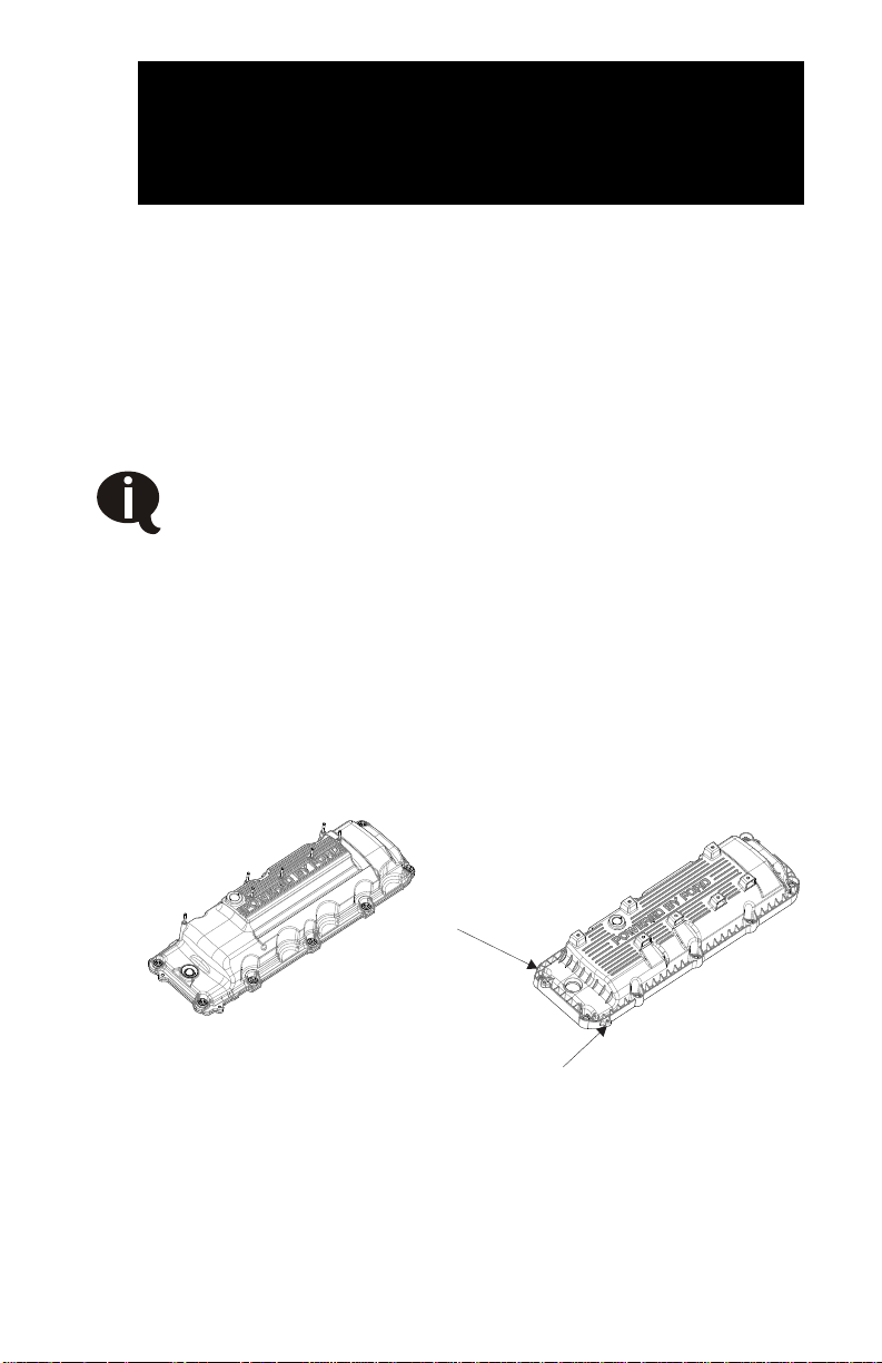
□ Determine which valve covers your vehicle has been
manufactured with (Figure 3.1). If your vehicle was
manufactured before 05-Dec-2011 no modifications are
required.
As of 05-Dec-2011 Ford has issued a running change to
the valve covers installed on 6.2L V8 gas engines. Valve
covers on vehicles manufactured before 05-Dec-2011 can
be identified by the wire harness/spark plug wire stud
mounts and are made of aluminum. Valve covers on
vehicles manufactured after 05-Dec-2011 are composite
and black in color. (Figure 3.1)
The main bracket supplied has been designed and
machined to fit valve covers on vehicles manufacture
before and after 05-Dec-2011. However valve covers on
vehicles manufactured after 05-Dec-2011 require
modifications for proper fitment.
Valve Covers Manufactured
Before 05-Dec-2011
(Aluminum)
Valve Covers Manufactured
After 05-Dec-2011
(Composite)
This corner gets trimmed
This tab gets removed
Figure 3.1
Page 18
VMAC – Vehicle Mounted Air Compressors
Toll Free: 1-800-738-8622
Fax: 1-250-740-3201
16
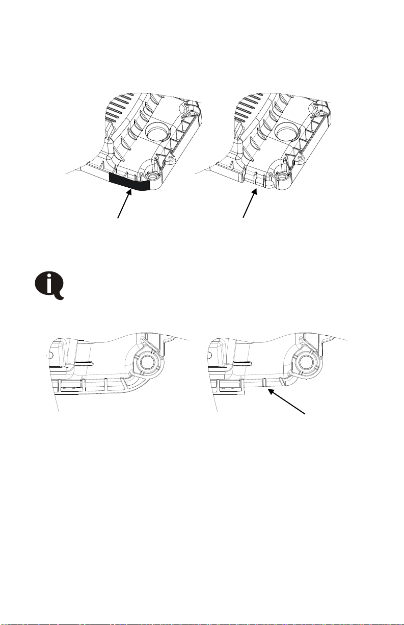
□ On Vehicles manufactured after 05-Dec-2011 with composite
valve covers remove the webbed area shown using a die
grinder or pneumatic cut off wheel (Figure 3.2).
Figure 3.2
When modifying the valve cover it is important to only
remove the webs indicated and not cut past the face shown
in Figure 3.3. Cutting into the main valve cover body may
risk cutting the O-ring sealing the valve cover to the
cylinder head.
Before Webs Removed
After Webs Removed
Do Not Cut Past
This Face
Figure 3.3
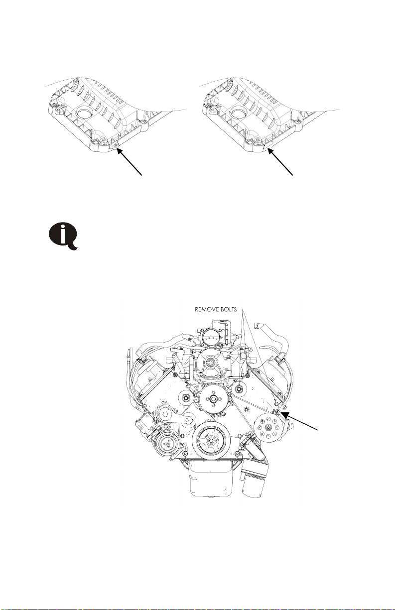
□ On Vehicles manufactured after 05-Dec-2011 with composite
valve covers remove the wire harness mounting tab shown
using a die grinder or pneumatic cut off wheel (Figure 3.4).
Page 19
VMAC – Vehicle Mounted Air Compressors
Toll Free: 1-888-241-2289
Fax: 1-250-740-3201
17
Remove Wire Harness
Mounting Tab
Mounting Tab Removed
Figure 3.4
When fitting the main bracket it is important the bracket
sits flush on all mounting surfaces. Ensure the bracket is
not touching the valve cover when installed. If necessary
trim the valve cover as required until proper fitment is
obtained.
Wire Hold
Down Clip
Figure 3.5
Page 20
VMAC – Vehicle Mounted Air Compressors
Toll Free: 1-800-738-8622
Fax: 1-250-740-3201
18
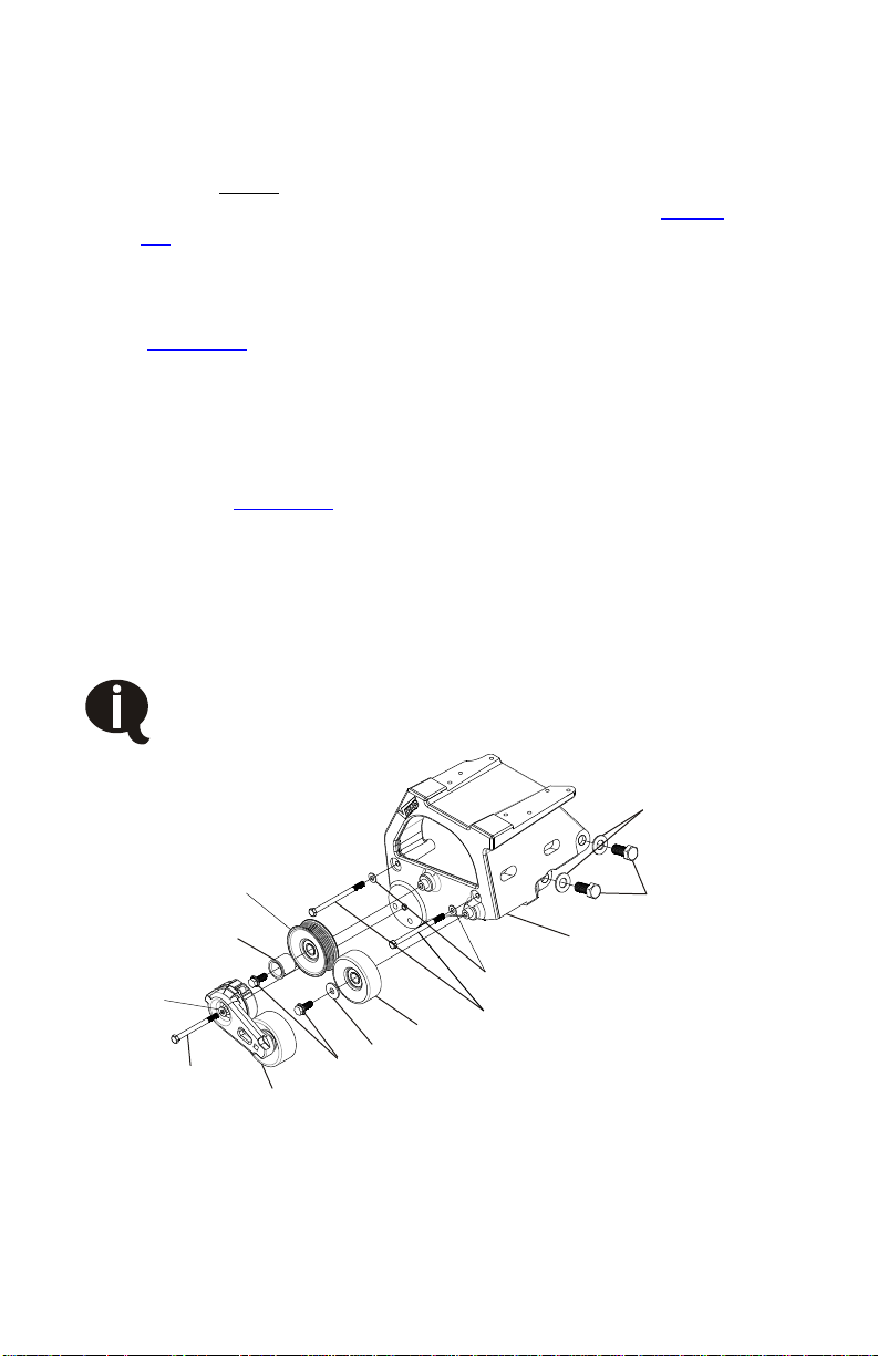
□ Remove the two driver side front cover bolts (Figure 3.5).
□ Remove the bolt from the idler on the driver's side of the
engine. Leave the idler and OEM belt on the engine. The idler
is resting on a post and will not release belt tension. (Figure
3.5).
□ Remove wire hold down clip from wire loom on front cover.
Secure with supplied barbed tie strap in back of same hole
(Figure 3.5).
□ Fit the main bracket over the front of the engine making sure
that wires are not pinched.
□ Secure the bracket to the engine with the bolts supplied as
shown in Figure 3.6. Position bracket tight against engine and
install all 5 bolts. Do not tighten until all bolts have been
bottomed against the bracket and the bracket has been
checked to ensure it is positioned correctly and tight against
the engine. Then snug all bolts, gradually tightening at first,
then finally tighten the two M16 bolts, and then finish with
tightening the three M8 bolts.
If this procedure is not followed, the bracket and
fasteners may be excessively stressed and may lead to
failure.
5/8 WASHER
M16 X 35 BOLT
MAIN BRACKET
5/16 WASHER
M8 X 120 BOLT
BACK IDLER
10MM FENDER WASHER
M10 X 25 BOLT
6 RIB IDLER
TENSIONER PIVOT POST
TENSIONER
M8 X 100 BOLT
5/16 WASHER
Figure 3.6
M10 x 30 BOLT
Page 21

VMAC – Vehicle Mounted Air Compressors
Toll Free: 1-888-241-2289
Fax: 1-250-740-3201
19
□ Double check that no wires are pinched between the bracket
and the engine.
□ Remove the inlet valve from the compressor and cover the
opening.
□ Place the compressor in position on the mounting bracket and
secure to the bracket with the 4 supplied bolts (See warning
below).
Note the two different bolt lengths when removing the
inlet valve. They must go back in the same location
(long bolts closest to the air filter) otherwise they will
bottom out and damage the housing when tightened.
□ Replace the inlet valve on the compressor. Ensure the sealing
o-ring is in position on the rotor housing.
3.2 Installing Drive Belts and Pulleys
□ Remove the center bolt from the OEM crankshaft pulley and
discard. Install the VMAC pulley with the supplied M14 x 110
bolt and 9/16 washer. Lightly oil bolt threads before installing
into crankshaft. Once the bolt is finger tight rotate the VMAC
pulley counter-clockwise until the three lugs are against the
web of the OEM pulley. Torque Bolts as per Ford
specifications. For your convenience, the specifications at the
time of this printing were: torque to 129 ft•lbs then an
additional 90 degrees.
□ Remove the captive mount bolt from the tensioner and discard.
The bolt may be pressed or lightly hammered out.
□ Install the VR tensioner and idlers on the bracket and torque
the fasteners to specifications. Insure the pivot post is installed
on the ribbed idler (Figure 3.6)
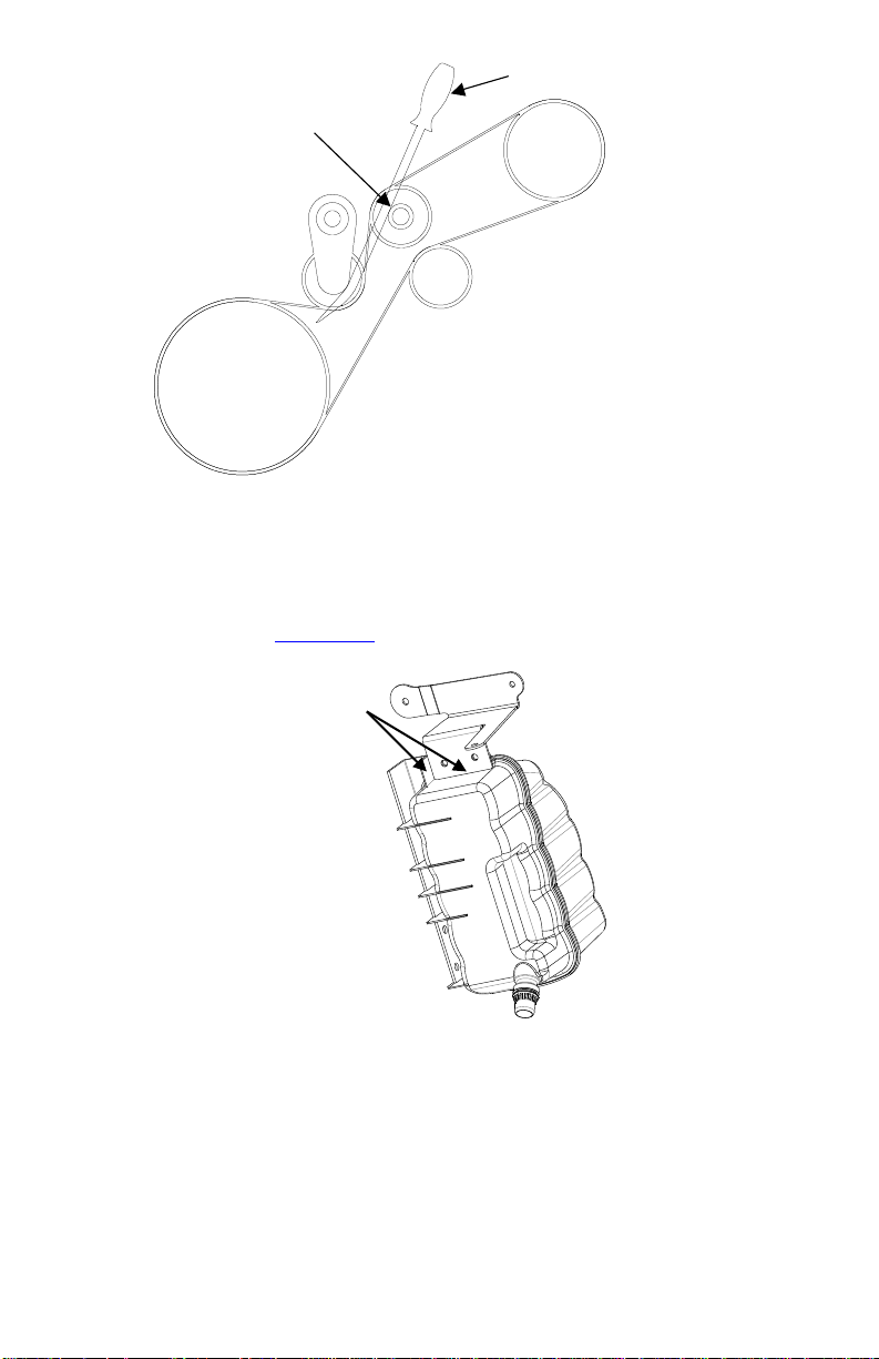
□ Install the VR drive belt (Figure 3.7). While the fan is not
installed, the tensioner can be rotated using the 3/8" square
hole. After the fan is installed, the tensioner can be rotated by
using a prybar against the idler pry-post as shown in figure 2.3.
Page 22
VMAC – Vehicle Mounted Air Compressors
Toll Free: 1-800-738-8622
Fax: 1-250-740-3201
20
Post
Use Prybar To Release Tensioner
Figure 3.7 – VR70 Belt Layout
3.3 Installing Other Components
□ Using the supplied brackets, mark and drill 11/32" holes in the
degas bottle (Figure 3.8)
Figure 3.8
Place supplied bracket
against these two edges and
use as a template to drill two
11/32” holes.
Page 23
VMAC – Vehicle Mounted Air Compressors
Toll Free: 1-888-241-2289
Fax: 1-250-740-3201
21
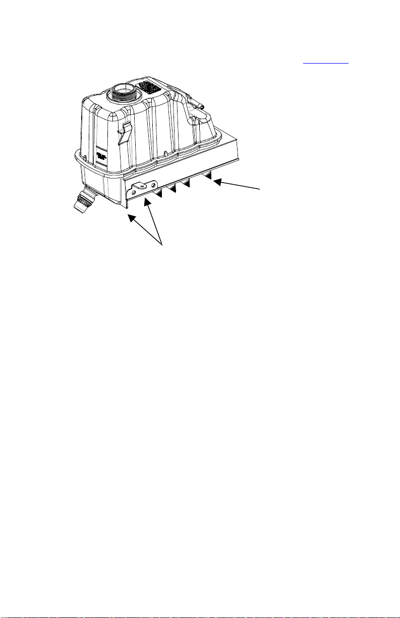
□ Using the supplied brackets, mark and drill 11/32" holes in the
degas bottle and remove corner webbing shown (Figure 3.9)
Place Bracket Against These
Two Edges And Use As A
Template To Drill Two 11/32’
Holes
Remove Corners
Shown In Black
Figure 3.9
Page 24
VMAC – Vehicle Mounted Air Compressors
Toll Free: 1-800-738-8622
Fax: 1-250-740-3201
22
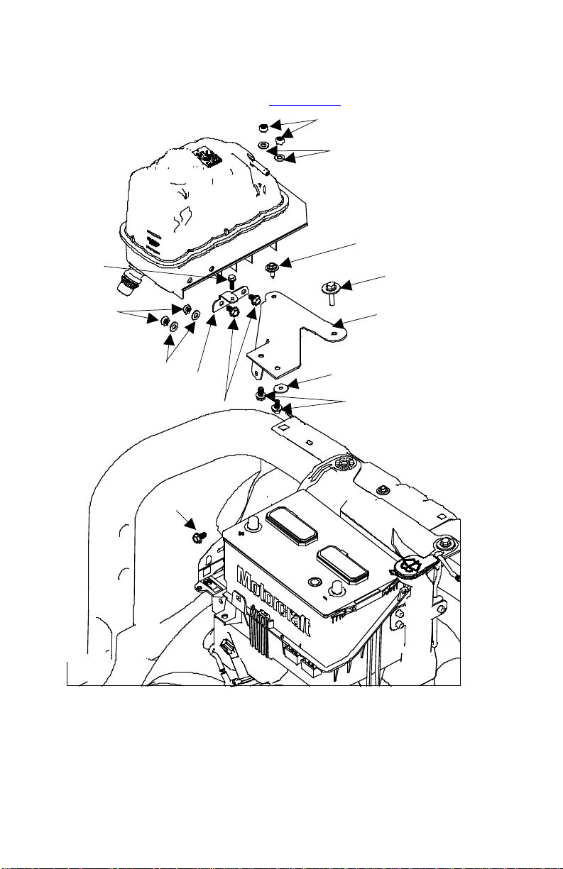
□ Install the modified degas bottle in front of the battery on the
passenger side as shown in Figure 3.10.
OEM Battery Box Bolt
OEM Fender Bolt
Fender Washer
Degas Fender Bracket
M8 Nuts
5/16 Washers
M8 x 16 Bolts
M8 x 16 Bolts
Degas Battery Bracket
M8 x 16 Bolts
5/16 Washers
M8 Nuts
M6 x 20
Bolt
Figure 3.10
Page 25
VMAC – Vehicle Mounted Air Compressors
Toll Free: 1-888-241-2289
Fax: 1-250-740-3201
23
3.4 Installing the Cooler
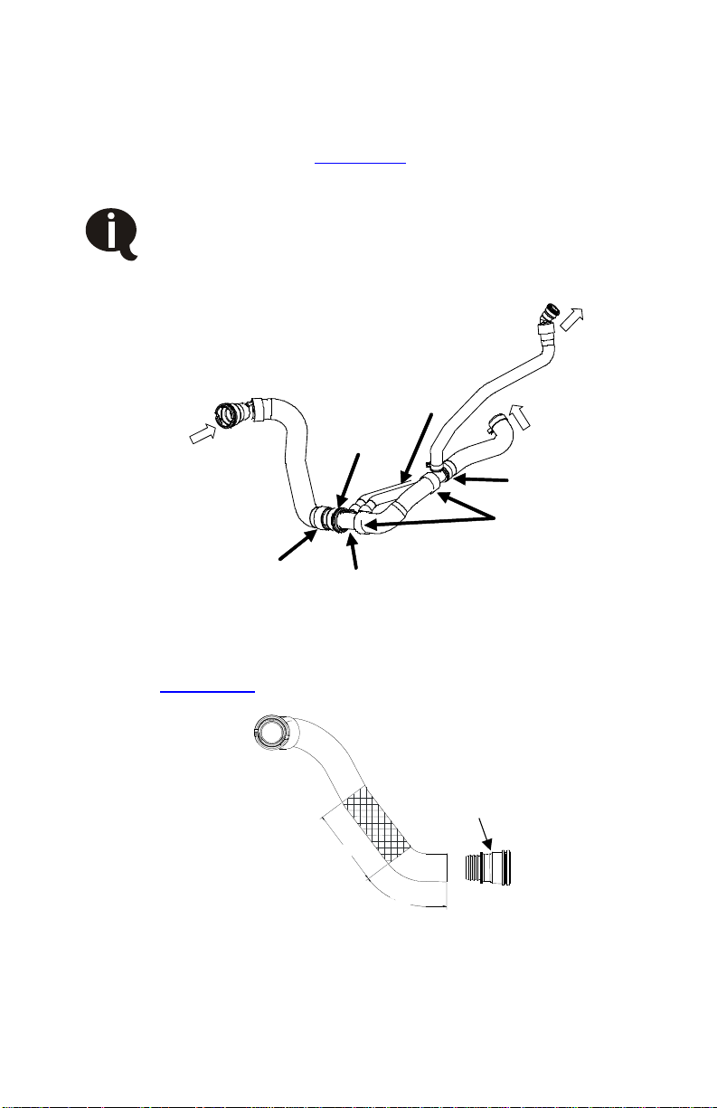
□ Cut the three molded plastic cuffs clamping the lower radiator
hoses to the degas bottle tee, oil cooler diverter valve, and the
OEM quick connect (Figure 3.11). After cutting, separate the
hoses from the fittings.
Do not damage the diverter valve or the hoses as they
will be used again.
From
Radiator
OEM
Quick
Connect
Oil Cooler
Hoses
Cut Cuff
Cut Cuffs
To Degas
Bottle
To Engine
OEM Diverter
Degas Tee
Figure 3.11
Cut the passenger side radiator hose 5-3/4” from the lower
OEM quick connect, remove approximately 8” and insert the
OEM diverter with the two small hose spigots facing to the
rear (Figure 3.12 & Figure 3.14). Secure with hose clamps.
5 –3/4”
OEM Quick
Connect
8” Approx.
Figure 3.12
Page 26
VMAC – Vehicle Mounted Air Compressors
Toll Free: 1-800-738-8622
Fax: 1-250-740-3201
24
□ Remove the OEM Degas Tee and replace with supplied 1-1/2”
connector tube (Figure 3.14).
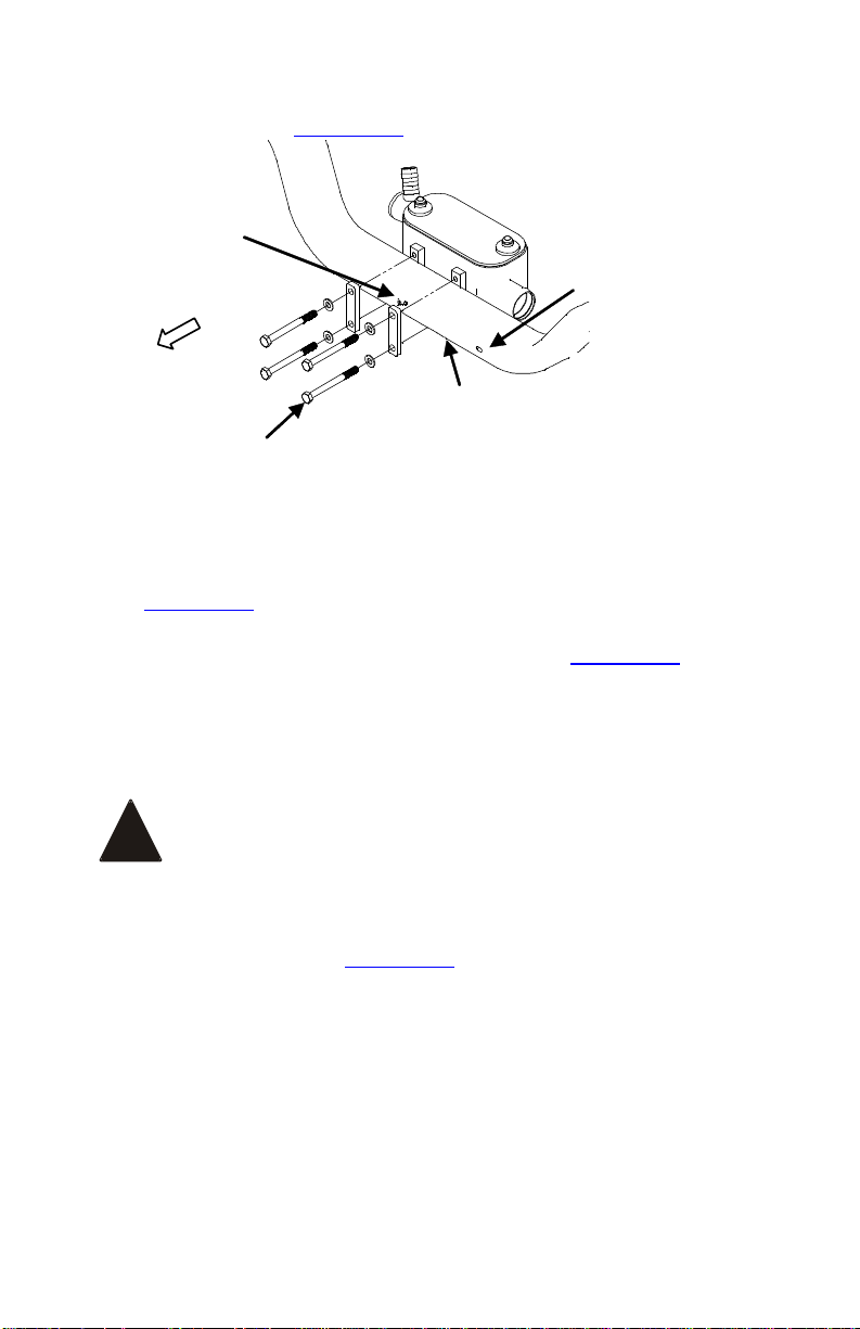
Impact Sensor
Location
Fog Light
Connector
Location
Front
Cross member
M10 x 100mm
Long Bolts (4x)
Figure 3.13
□ Position the cooler in the center of the front cross-member so
that it is just above the sway-bar with the oil ports facing up
(Figure 3.13).
□ Install bolts through the flat mounting straps (Figure 3.13) and
place them on the front of the cross-member on each side of
the impact sensor. Note the impact sensor is located in the
centre of the cross-member, the driver side wire connection is
for fog lights if equipped.
Do not strike the impact sensor as this could cause
the airbags to actuate.
□ Thread the bolts into the matching holes on the cooler mounts
and tighten securely (Figure 3.13).
!
Page 27
VMAC – Vehicle Mounted Air Compressors
Toll Free: 1-888-241-2289
Fax: 1-250-740-3201
25
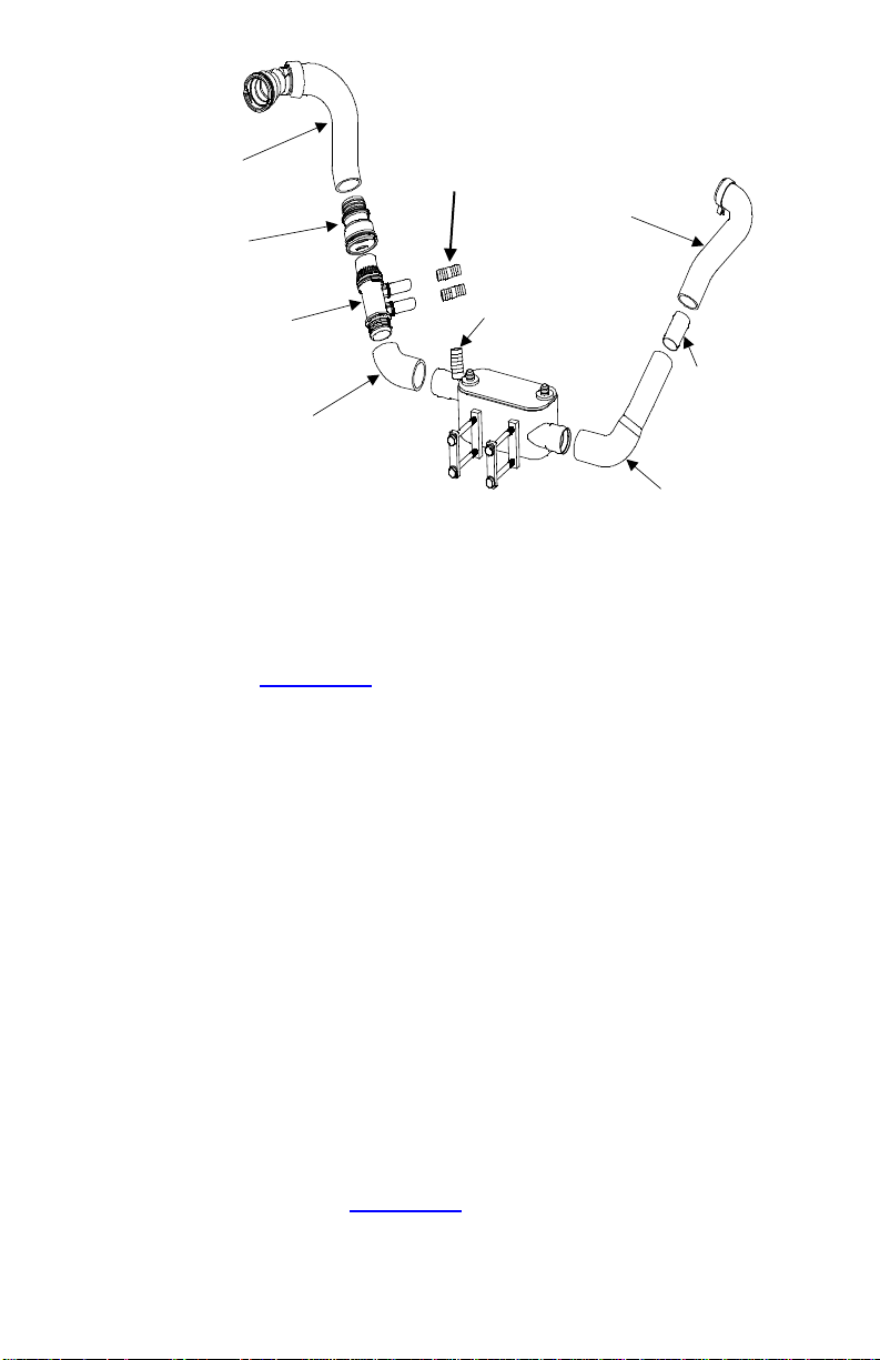
OEM Quick
Connect
OEM
Diverter
Valve
Existing Cut
Passenger
Side Radiator
Hose
To Degas
Bottle
Hose Barbs to
Oil Cooler Lines
Existing Driver
Side Radiator
Hose
1-3/4”
Connector
Tube
Existing Driver
Side Radiator
Hose
Existing Cut
Passenger
Side Radiator
Hose
Figure 3.14
□ Connect the driver side radiator hose to the cooler and secure
with a hose clamp. Trim as necessary if any kinking of hose
occurs (Figure 3.14).
□ Cut and extend the OEM oil cooler lines with the supplied 3/4”
hose barb connectors. When pushing the oil cooler hoses onto
the 3/4" hose barb do not push on the entire way, 1” of hose
barb should be left showing in the centre of the barb. Ensure
that the hoses are well clear of the crank pulley and secure
with hose clamps.
□ Remove 1" of the upper radiator hose where it connects to the
radiator by cutting the hose at the rear edge of the cuff holding
the hose to the OEM radiator quick connect. Discard cuff and
cut section of hose.
□ Using the supplied hose clamp, reinstall the OEM quick
connect into the upper radiator hose.
□ Cut the cuff holding the degas hose quick connect to the
degas hose and remove the connector. Cut and discard 5” of
the Degas hose (Figure 3.15).
Extend Oil Cooler
Lines With Hose
Barb Connectors
Page 28
VMAC – Vehicle Mounted Air Compressors
Toll Free: 1-800-738-8622
Fax: 1-250-740-3201
26
5”
Removed Degas
Quick Connect
Degas Hose
Discarded Section
of Degas Hose
Figure 3.15
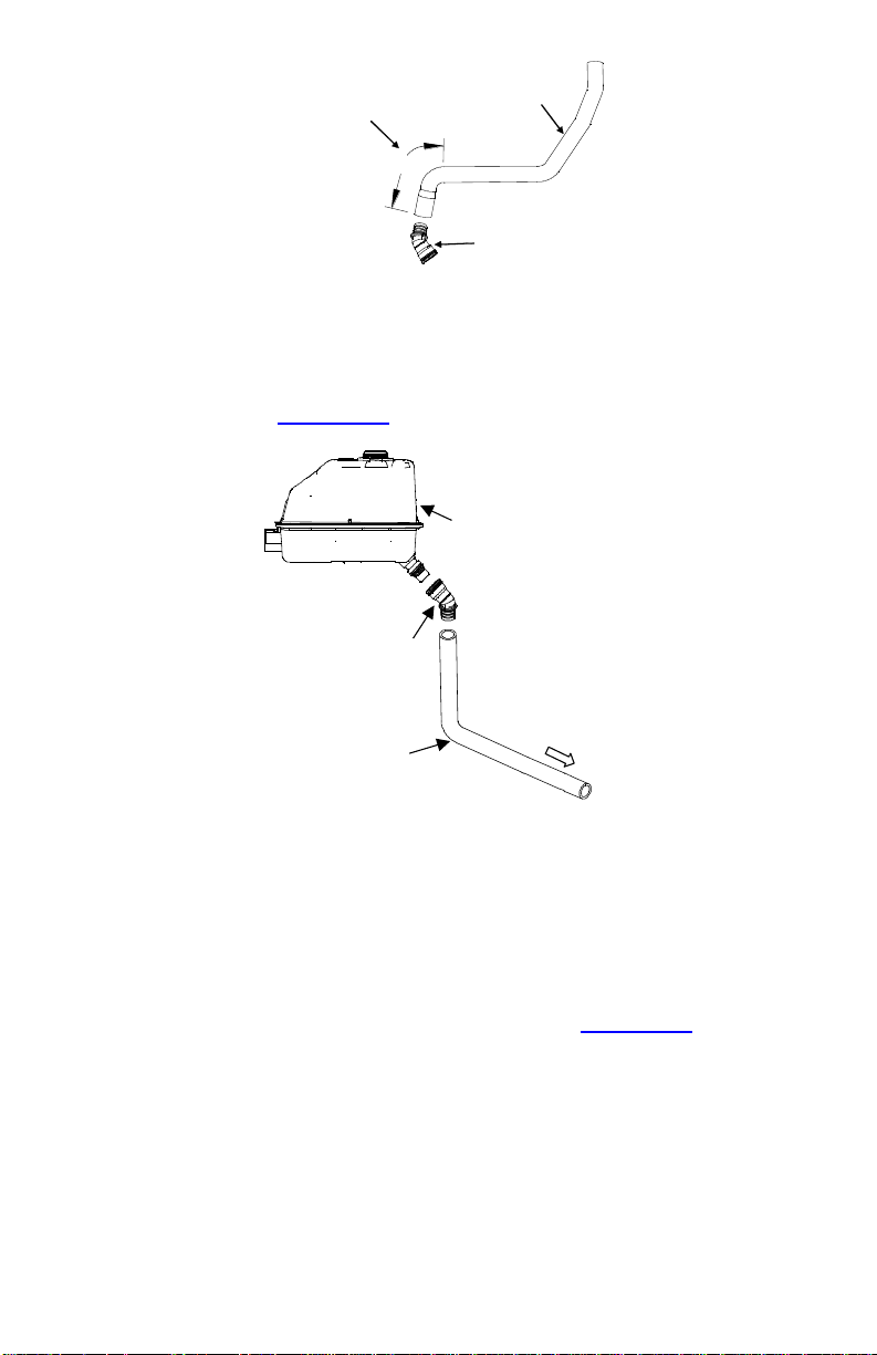
□ Reconnect the degas connector with the modified OEM degas
hose, then to the cooler and the degas bottle. Secure with
hose clamps (Figure 3.16).
Modified Degas
Hose
Existing Degas
Connector
Degas Bottle
To Cooler
Figure 3.16
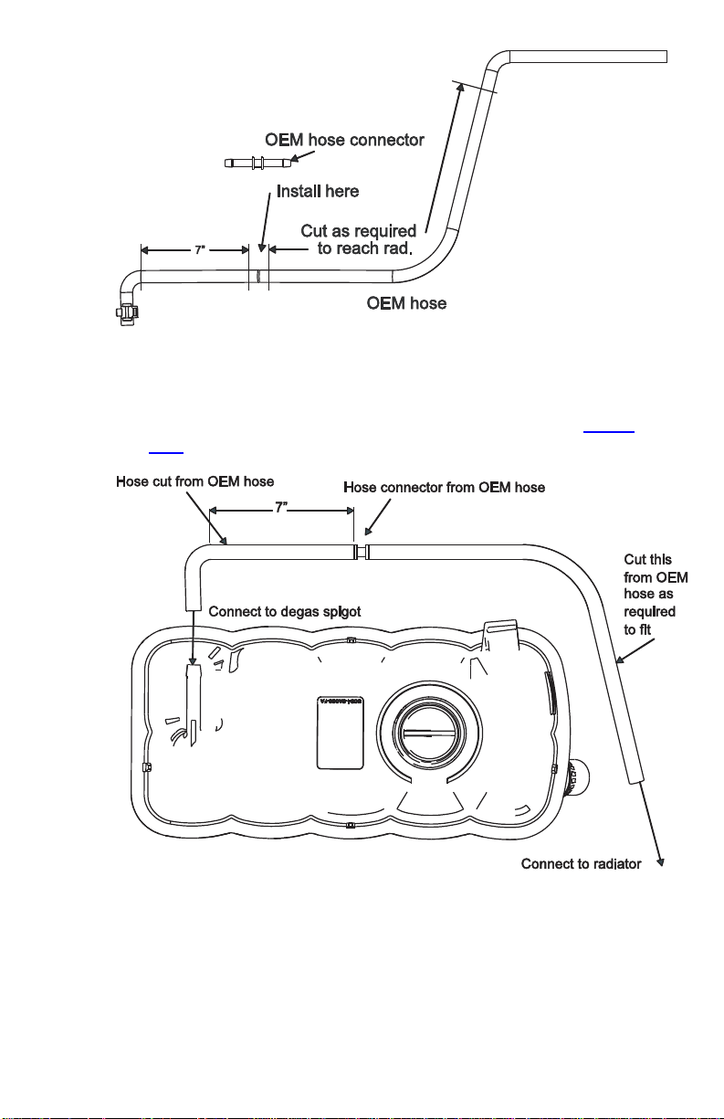
□ Modify the OEM Degas vent hose as shown. Cut the 90 deg.
elbow end, 7” from radius, and install the hose connector in to
the cut end of the hose. Then use the large radius portion of
the remaining hose to connect to the hose connector and cut
as required to connect to the radiator spigot (Figure 3.17).
Page 29
VMAC – Vehicle Mounted Air Compressors
Toll Free: 1-888-241-2289
Fax: 1-250-740-3201
27
Figure 3.17
□ Install the modified OEM Degas vent hose as shown (Figure
3.18).
Figure 3.18
Page 30

VMAC – Vehicle Mounted Air Compressors
Toll Free: 1-800-738-8622
Fax: 1-250-740-3201
28
Part 4: Installing the Tank and
Hoses
Depending on other installed equipment, it might be
necessary to move the air/oil separation tank from its
intended location. The hoses used in VMAC
compressor systems have a specific inner liner that is
compatible with our compressor oil. Use of hoses
other than those supplied or recommended by VMAC
may cause compressor damage and may void your
warranty. Please contact VMAC for replacement hoses
and further information.
4.1 Installing the Tank and Mount Brackets
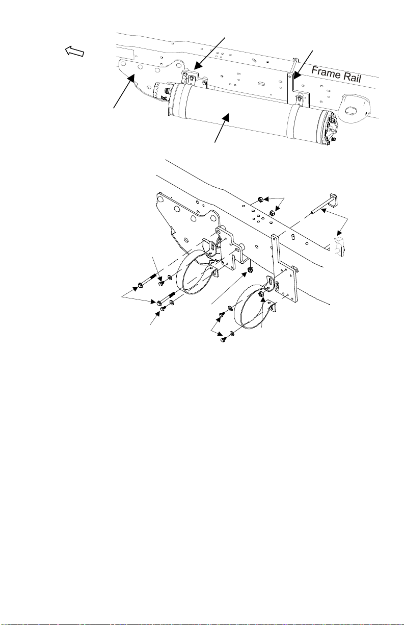
□ The tank (Figure 4.1) will mount to the driver side frame rail
behind the suspension radius arm mount.
!
Page 31
VMAC – Vehicle Mounted Air Compressors
Toll Free: 1-888-241-2289
Fax: 1-250-740-3201
29
Suspension Radius
Arm Mount
Tank
Front Tank Mount
Rear Tank Mount
Front
C-Clips &
5/16 x 4-1/2
Bolts
5/16 Nuts &
Washers
OEM Crossmember Nut
5/16 x 2 Bolts &
Washers
3/8 Nut
5/16 x1/2 Bolts &
Washers
5/16 x1/2 Bolts
Washers
5/16 x1/2 Bolts &
Washers
Figure 4.1
□ Place the tank on a workbench with the front (oil filter end) of
the tank to your left and remove the oil filter.
□ Remove the two 1/4 inch clamp bolts from the C-clamps.
Expand the clamps slightly and slide them over the front of the
tank.
□ Apply Loctite and insert 5/16 x 1/2 inch bolts through the C-
clamps and thread them into the mount brackets, but do not
tighten.
□ Install a suitable 3/4-inch fitting (not supplied) in the back of
the tank.
Page 32
VMAC – Vehicle Mounted Air Compressors
Toll Free: 1-800-738-8622
Fax: 1-250-740-3201
30
The tank will mount on the driver side frame rail under
the cab and must be level. Variations in frame design
may affect the position of the rear tank mount bracket.
Always check fit before tightening the fasteners.
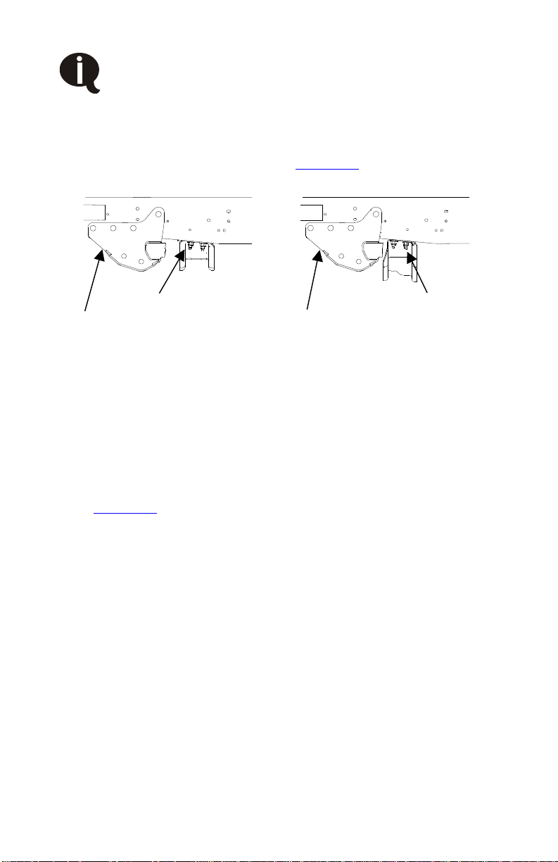
□ Remove 1 of 2 OEM nuts attaching the transmission cross
member to the frame. Depending on truck configuration crossmember location may differ. See Figure 4.2.
Remove Front nut
Remove Rear nut
Suspension Radius
Arm Mount
Suspension Radius
Arm Mount
Figure 4.2
□ Remove the plastic hold down for the wiring harness on the
inside of the frame that interferes with the tank mount bolt.
Secure the wiring harness with supplied P-clamp onto back of
the tank mount bolts.
□ Support the tank and tank mount assembly in place on the
outside of the frame behind the suspension radius arm mount
(Figure 4.1),
□ Adjust the position of the rear tank mount bracket for best fit
and to ensure that the tank will be level when mounted and to
provide adequate clearance for hose connections and filter
installation.
□ Mark the position of the C-clamps on the tank and the position
of the bracket on the frame. Remove then tank assembly and
place it back on the workbench.
□ Tighten all C-clamp mouthing bolts
□ Lift the tank and tank mount brackets into position and install
the two 5/16 inch bolts holding the front tank mount to the
frame and the OEM transmission cross member nut.
Page 33
VMAC – Vehicle Mounted Air Compressors
Toll Free: 1-888-241-2289
Fax: 1-250-740-3201
31
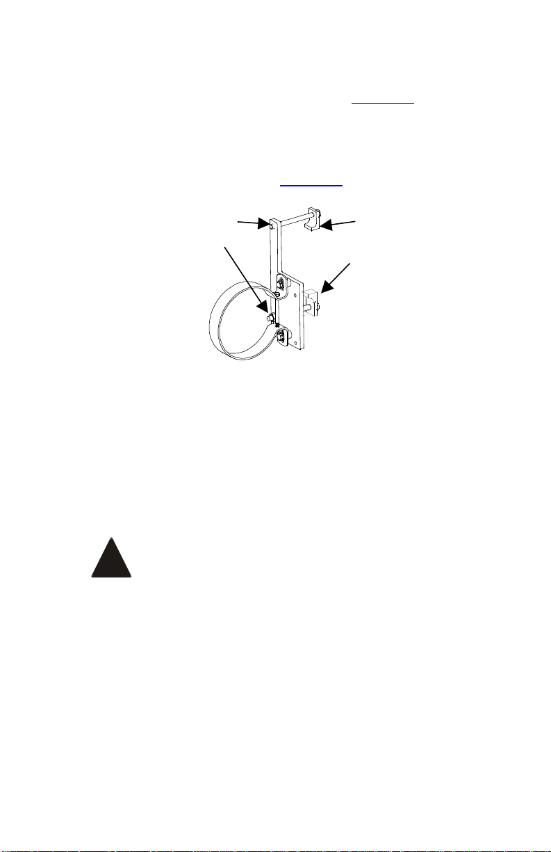
□ Thread the top bolt into the rear tank mount bracket. Ensure
the tank clip is hooked over the backside of the frame and no
wires or tubes are pinched or trapped (Figure 4.3).
□ Install the tank clip so it hooks around the back of the frame.
Insert the threaded end through the appropriate hole in the
bottom of the rear tank mount strap. Apply Loctite and start the
flange nut on the tank clip (Figure 4.3).
Tank Clip
Threaded Hole
Tank Clip
Flange Nut
Figure 4.3
□ If necessary, reposition the tank on the frame to provide
adequate clearance for hose connections and filter installation.
When the tank is correctly positioned ensure all bolts are
torqued to specification.
4.2 Installing the Hoses
When routing hoses make sure they do not come in
contact with moving parts, sharp edges or heat
sources.
□ Route the straight end of the 3/4 inch and the longest 1/2 inch
hoses over the cab mount and thread them into the matching
fittings on the tank but do not tighten.
□ Insert the 1/4 and 3/16 tubes into the fittings on the back of the
tank and cover them with high temperature loom. Route them
along the tank and outside of the frame rail.
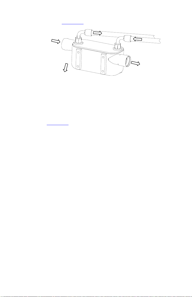
□ Route the 1/2 hose from the tank along the driver side frame
rail to the underside of the radiator, clear of suspension pinch
!
Page 34
VMAC – Vehicle Mounted Air Compressors
Toll Free: 1-800-738-8622
Fax: 1-250-740-3201
32
points and connect the 90 degree end to the driver’s side fitting
on the cooler (Figure 4.4).
From Radiator
To Engine
Front
From Tank
To Compressor
Figure 4.4
□ Route the 3/4-inch hose from the VR tank to the compressor
and connect the 45-degree end to the matching fitting.
□ Connect the shortest 1/2-inch hose between the compressor
and the 90-degree end to the passenger side fitting on the
cooler (Figure 4.4).
□ Route the 3/16 and 1/4 inch tubes up over the body mount
(clear of the exhaust manifold) and connect them to the
matching fittings on the compressor air inlet control valve.
□ Tighten all hose connections at the tank, cooler and
compressor. Prevent the hoses from twisting during tightening.
□ Bunch all hoses together, secure them with tie-straps and
protect them where they might rub. Make sure that they are
clear of hot exhaust parts or moving parts, including the
steering column.
□ Move the steering between left and right lock positions to
check clearance.
□ Apply a light film of compressor oil to the filter gasket and
install the filter on the tank. Tighten the filter an additional 3/4
turn after the gasket contacts the base.
Page 35

VMAC – Vehicle Mounted Air Compressors
Toll Free: 1-888-241-2289
Fax: 1-250-740-3201
33
4.3 Adding Oil to the System
You must use the VMAC supplied and approved
compressor oil in this system. Failure to use this
special oil will result in damage to the compressor and
may void your warranty.
□ Remove the fill plug from the air inlet control valve and pour oil
into the oil fill hole on the inlet control valve using a funnel.
Turn the compressor clutch clockwise with a ratchet and a 1/2inch socket using the hex head bolt at the centre of the
compressor clutch during the fill process.
□ Allow 5 minutes for the oil to drain into the tank, then check the
level at the sight glass at the front of the tank. Continue
adding oil until the level is correct.
□ Install the fill plug in the inlet control valve and tighten it
securely.
Do not overfill the system. Overfilling the system with
oil can flood the sight glass window and make the
system appear empty.
!
!
Page 36
VMAC – Vehicle Mounted Air Compressors
Toll Free: 1-800-738-8622
Fax: 1-250-740-3201
34
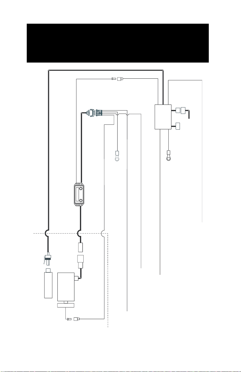
Part 5: Installing the Control
Components
Control Box
White
Interface
Connector
Throttle
Controller
Green 4 pin
connector
White
Red
Red
Red
White
White
Compressor
Inlet valve
Clutch
G
G
r
r
e
e
e
e
n
n
Black
Connect to accelerator pedal
OEM Connector from
accelerator pedal
Black 3 pin
connector
To ground
To ground
Connect
Blue
ENGINE COMPARTMENT
Connect to OEM circuit
CDC64 YEL/ORG (early builds WHT/BLU)
Connect to white wire with a purple stripe at the SEIC harness
Connect to OEM blue wire CE913
Connect to the blue wire with grey stripe CLS05
Page 37

VMAC – Vehicle Mounted Air Compressors
Toll Free: 1-888-241-2289
Fax: 1-250-740-3201
35
5.1 Installing the Components
□ Install the control box in a convenient location in the cab,
positioned so that the wire harness will reach the compressor.
Keep wires away from the park brake mechanism.
Route wires clear of the steering column and pedals
so they do not contact moving parts. Before drilling
holes make sure that there are no OEM wire bundles
where you will be drilling.
□ Tie-wrap the throttle control under the dash away from moving
parts, positioned so that the idle down pressure (IDP) and
maximum RPM adjusting screws are accessible.
5.2 Connecting the In-cab Wiring
□ Unplug the OEM cable from the accelerator pedal and plug it
into the matching connector from the throttle control box. Plug
the cable from the throttle control into the matching connector
on the accelerator pedal.
□ Connect the two white interface connectors together.
□ Connect the red wire from the throttle controller to the
matching red wire from the control box.
□ Connect the green wires from the interface connector and the
throttle control to a good ground.
□ Connect the single red wire from the interface connector to
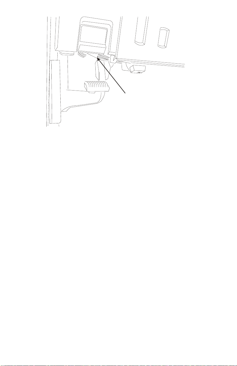
switched 12 volts. You can use circuit CDC64 (see wiring
diagram) located in the blunt cut bundle under the dash beside
the park brake (Figure 5.1).
□ Connect the white wire from the throttle controller to the “clean
tach out” circuit CE913 (see wiring diagram) at the blunt-cut
harness.
□ Solder and seal the black wire from the interface cable to the
white with purple stripe wire at the SEIC harness.
Page 38
VMAC – Vehicle Mounted Air Compressors
Toll Free: 1-800-738-8622
Fax: 1-250-740-3201
36
B
R
A
K
E
HOOD
Blunt cut harness
Figure 5.1
□ Solder and seal the long blue wire from the throttle to the blue
with gray stripe wire in the blunt cut bundle. (Early 2011MY
build trucks have two(2) blue with gray stripe wires. Test for
the correct one by measuring resistance to ground in all gears.
It should be open in all gears and connected in Park only.)
5.3 Connecting the Underhood Wiring
□ Cut a slit in the firewall plug under the firewall insulation and
feed the following wires into the engine compartment:
• gray harness with the green plug connector from the control
box
• gray harness with the black connector from the throttle
controller
• white wire with a bullet connector from the interface cable
□ Connect the two gray wires with the green plug connectors
together.
□ Connect the gray wire with the black connector to the matching
connector on the pressure transducer at the compressor.
□ Connect the white wire with the bullet connector to the
matching connector at the compressor clutch.
Page 39
VMAC – Vehicle Mounted Air Compressors
Toll Free: 1-888-241-2289
Fax: 1-250-740-3201
37
Part 6: Finishing the Installation
6.1 Reinstall OEM components.
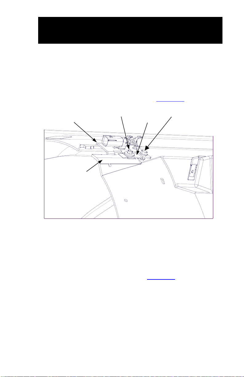
□ Install fan and modified fan shroud.
□ Install the fan shroud spacer and attach the fan wiring
connector bracket and wire connector (Figure 6.1).
Fan Wiring Connector
Bracket
OEM Bolt
Supplied
Bracket
M6 x 14 Bolt & Nut
Modified Fan
Shroud
Figure 6.1
□ Install the upper radiator hose. Secure with hose clamps.
□ Fill the cooling system with the manufacturer recommended
coolant.
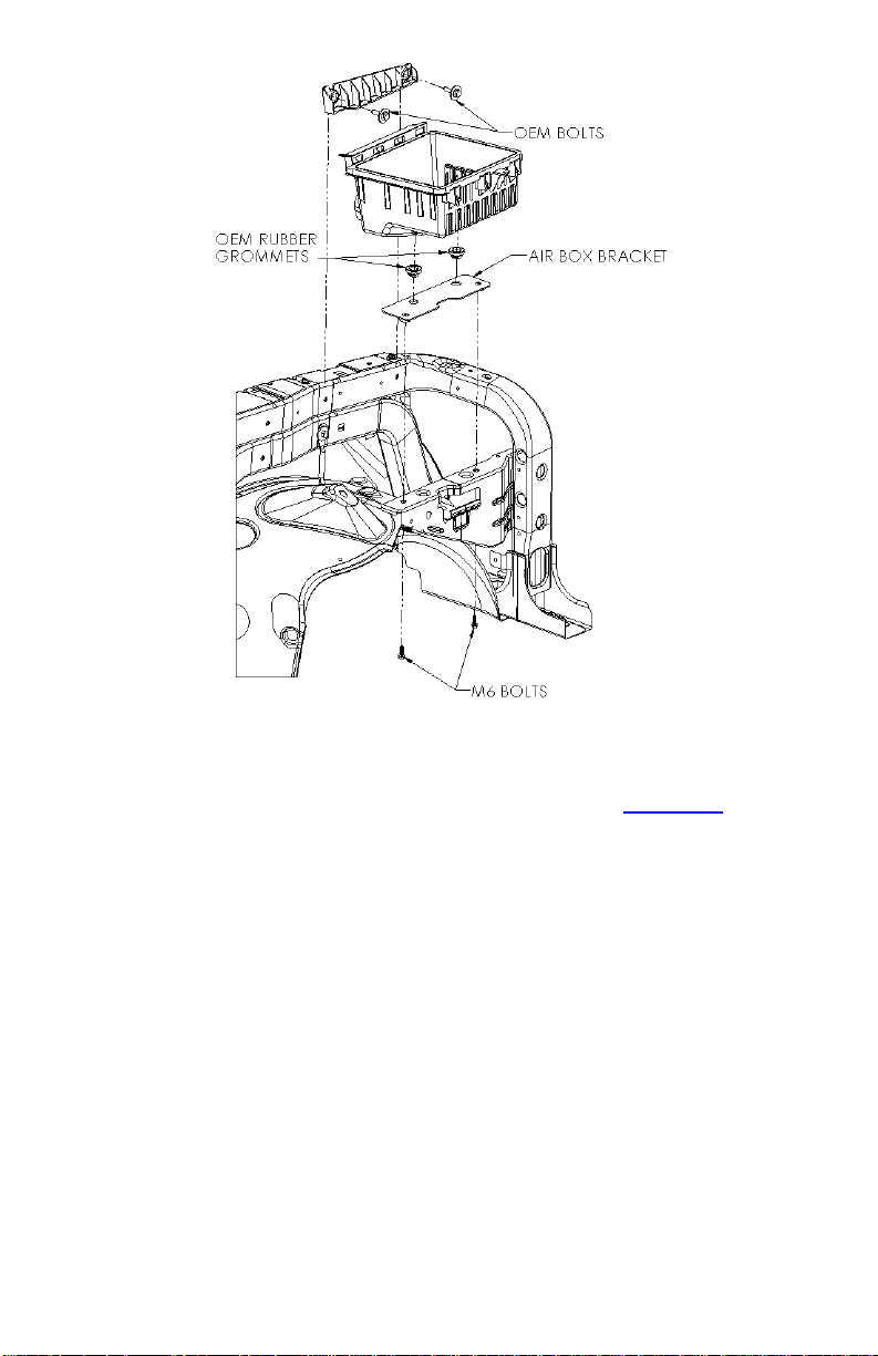
□ Install modified air box as shown in Figure 6.2
Page 40
VMAC – Vehicle Mounted Air Compressors
Toll Free: 1-800-738-8622
Fax: 1-250-740-3201
38
Figure 6.2
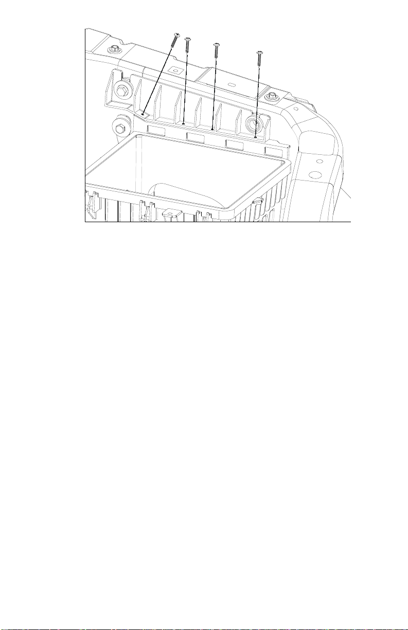
□ Drill pilot holes and attach the two pieces of the air box
together with the supplied 1" screws as shown in Figure 6.3.
Ensure that the screws will not protrude into the slots for the
air filter cover tabs.
Page 41
VMAC – Vehicle Mounted Air Compressors
Toll Free: 1-888-241-2289
Fax: 1-250-740-3201
39
Figure 6.3
□ Reinstall the power steering reservoir onto the fan shroud.
□ Reinstall the air filter and cover.
□ Reinstall the intake tube.
□ Cover all underhood wiring with plastic fireproof loom. Secure
the harnesses with nylon ties. Avoid contact with hot or moving
parts.
□ Pull all excess wiring back into the cab, bundle the wiring
together and tie it up out of the way under the dash.
□ Replace all dash panels and other covers removed during
installation.
□ Reconnect the battery
6.2 Before Starting the Engine Checklist
Make sure that the following have been completed:
□ Check the vehicle coolant.
Page 42

VMAC – Vehicle Mounted Air Compressors
Toll Free: 1-800-738-8622
Fax: 1-250-740-3201
40
□ Check the compressor oil level.
□ Do a final inspection to make sure that everything has been
completed and tightened.
□ Perform a final belt alignment check.
□ Check all wiring for security and protection.
6.3 Safety Test
□ Place the automatic transmission in Park and apply the park
brake. Turn the ignition key “ON” but do not start the engine.
□ Check the control box to see if there is a number showing in
the display. If there is no display, there is no power to the
control box.
□ Push the control box “ON” button. The green LED should
come on and you should hear the compressor clutch engage.
□ Release the park brake. The green LED should flash, “PARK
BRAKE” will show on the display and the compressor clutch
should disengage. Apply the park brake again, wait 20
seconds and push the “ON” button. The green LED should
come on and the compressor clutch should engage.
□ Turn the ignition key “OFF”.
The engine must be running to complete the final step
in the safety test. This will be done after the pre-start
checks have been completed.
If the vehicle fails the test, check the wiring to make
sure that all the connections are correct and secure. If
you require additional assistance, contact your local
VMAC dealer. Call 1-800-738-8622 or 250-740-3200.
!
!
Page 43

VMAC – Vehicle Mounted Air Compressors
Toll Free: 1-888-241-2289
Fax: 1-250-740-3201
41
6.4 After Starting the Engine Checklist
Place the vehicle in a safe operating position and
block the wheels. Ensure that there are no people
around the vehicle before beginning the test.
□ Install a test tool on the air tank outlet and close the ball valve.
□ With the automatic transmission in PARK and the park brake
applied, start the engine and allow it to reach operating
temperature. Push the control box “ON” button. Engine speed
should increase to 1800-2200 rpm and then reduce to 10501100 rpm.
□ With the wheels blocked, place your foot firmly on the brake
pedal, shift the automatic transmission out of PARK and into
REVERSE. The engine should drop to OEM base idle (about
650 RPM) and the control box green light should stay on.
Repeat this test in all gear selector positions to make sure that
the engine does not idle up unless the selector is in PARK.
□ Operate the system with an air tool or with the test tool for at
least 1/2 hour (1 hour preferred).
□ Road test the vehicle for approximately 14 miles (20 km).
□ Watch the underhood operation to make sure that belts rotate
properly and nothing is rubbing or contacting hot parts.
□ Check all components once the engine is turned off and the
system has cooled.
□ Check the vehicle coolant after the vehicle reaches operating
temperature.
□ Check the compressor oil level after the vehicle has been shut
down and the oil level has had time to stabilize.
!
Page 44
VMAC – Vehicle Mounted Air Compressors
Toll Free: 1-800-738-8622
Fax: 1-250-740-3201
42
6.5 Setup, Performance Testing and Adjustments
This system has been adjusted at the factory for general operation.
If your tests indicate that adjustment is necessary, refer to the
owner’s manual for specific instructions on how to adjust the
system.
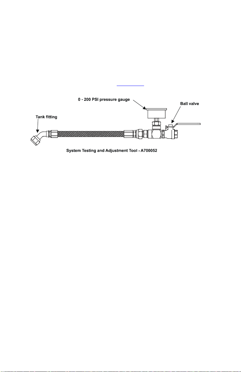
You can test the system operation using the tools that will be
operated by the system or you can test operations using an orifice
in the outlet to simulate tool use (Figure 6.4).
Figure 6.4
1. Install the test tool in the tank outlet fitting.
2. Make sure that the ball valve is closed.
3. Place the automatic transmission in PARK and fully apply the
park brake.
4. Allow the vehicle to run until the engine is at operating
temperature.
5. Operate the air compressor system until the oil is warm.
6. Observe the pressure gauge. Pressure should be
approximately 150 psi.
7. Open the ball valve on the test tool and observe the engine
tachometer. Engine speed should increase to about 1,800 to
2,200 RPM.
8. Close the air valve slowly to allow the system pressure to rise.
9. Once the system pressure is at maximum, slowly open the ball
valve on the test tool until the pressure on the gauge begins to
drop. Engine speed should start to ramp-up when air pressure
drops to approximately 140 psi.
Page 45
VMAC – Vehicle Mounted Air Compressors
Toll Free: 1-888-241-2289
Fax: 1-250-740-3201
43
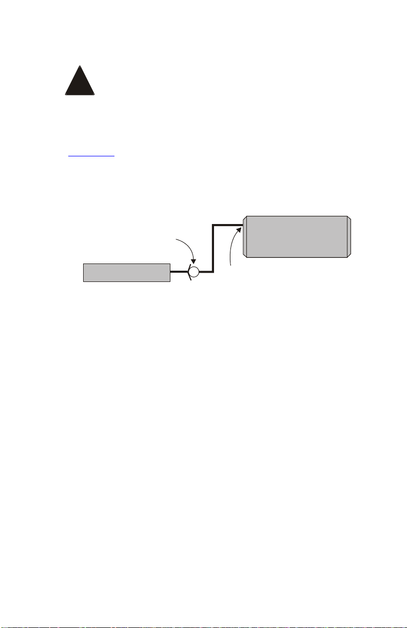
6.6 Auxiliary Air Receiver
If you intend to use an auxiliary air receiver with this
system you must observe the following installation
procedure to prevent damage to the system.
The line from the VMAC tank to the auxiliary air receiver must
have a one-way check valve installed to prevent blow back from
the auxiliary tank to stop moisture from entering the VMAC tank
(Figure 6.5).
The line to the auxiliary tank must not be installed in the bottom of
the tank, but must be installed as high as possible to prevent water
from entering the line.
Install the line as high as
possible, NOT on the
bottom of the auxiliary tank
VR Tank
One-way check valve
Auxiliary Tank
Figure 6.5
!
Page 46
VMAC – Vehicle Mounted Air Compressors
Toll Free: 1-800-738-8622
Fax: 1-250-740-3201
44
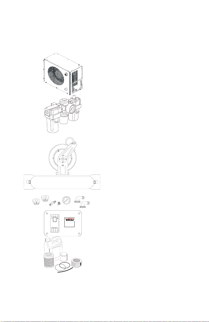
Accessory Products from VMAC
The following accessory products for your VR compressor system
are available from VMAC. For more information or to order these
products, call 1-800-738-8622.
Eliminator Aftercooler
Removes up to 80% of moisture
from compressed air. Quick
installation, automatic drain and
compact design
Filter Regulator
Lubricator
Removes lubricants, water and dirt
from the air stream. Adds atomized
tool oil to lubricate tools. Reduces
pressure for longer tool life.
Hose Reel
Secure, compact, retractable hose
storage in a sturdy reel.
Air Receiver Tank
Thirty-five gallon capacity in a
compact tank, complete with
fittings and a gauge.
DE-ICING
HEATER
De-icer Kit
Insulated rope heater prevents
freezing of lines and regulator.
Service Kits
Using OEM service products will
extend the life of your system.
Includes oil, filters, seals and Orings. 200 hour and 400 hour
service interval kits are available
Page 47

This page intentionally left blank
Page 48

This page intentionally left blank
Page 49

This page intentionally left blank
Page 50

VMAC – Vehicle Mounted Air Compressors
Toll Free: 1-888-241-2289
Fax: 1-250-740-3201
Warranty Registration
This form must be fully completed and returned to VMAC at the
time of installation. Warranty may be void if this form is not
received by VMAC within 30 days of installation.
VMAC’s Warranty policy and registration can be viewed online
at: www.vmacair.com/warranty
VMAC Dealer Information
Company Name: __________________________________________
City: _____________________ State / Province:_______________
Installer Information
Company Name: _____________________________________
City: _____________________ State / Province:______________
Installation Date: _____/_____/_____
Day Month Year
Owner Information
Company Name: __________________________________________
Address: ________________________________________________
City: _____________________ State / Province:_______________
Zip/Postal: ________________ Phone #: (____) ____ - _____
Email Address: ___________________________________________
Vehicle Information
Year: ____________________ Make: _________________
Vehicle Identification Number: ___________________________
Unit #: ___________________
Product Information
System Identification Number: V _ _ _ _ _ _ _ _ _ _ _ _
Compressor Serial Number: P_ _ _ _ _ _ _ _ _ _ _ _
Throttle Control Serial Number: _ _ _ _ _ _ _ _ _ _ _ _
AOST Serial Number: _ _ _ _ _ _ _ _ _ _ _ _
Submitted by
Name: ____________________ Contact: _________________
Page 51

Page 52
Manufactured by
PH 250-740-3200
FX 250-740-3201
TF 1-800-738-8622
1333 Kipp Road, Nanaimo, BC, V9X 1R3 Canada
www.vmacair.com
 Loading...