

Vmac V910020 Installation Instructions Manual
www.vmacair.com
®
AIR INNOVATED
TM
www.vmacair.com
Installation Manual for VMAC
System
V910020
2017+ Ford Super Duty F-250 – F-550
6.7 L Diesel
®
AIR INNOVATED
TM


VMAC - Vehicle Mounted Air Compressors
VMAC Technical Support: 888-241-2289
VMAC Knowledge Base: www.kb.vmacair.com
1
Tble of Contents
Safety ......................................................................... 3
Warranty
......................................................................4
General Information
...........................................................6
System Identification, Warranty Registration and Warning Labels
.............. 8
Preparing for Installation
.....................................................10
Relocating the ABS Hydraulic Control Unit (HCU)
............................. 16
Modifying the Hoses, Installing the Cooler
................................... 19
Modifying and Installing the Passenger Side Battery Tray, Air Intake and
VMAC Degas Bottle
..........................................................25
Modifying the Fan Shroud and Fan Stator
.................................... 31
Installing the Main Bracket, Idler Bracket and Compressor
................... 35
Installing the Air Oil Separator Tank
..........................................42
Hose Requirements
.......................................................... 45
Connecting the Hoses
...................................................... 46
Relocating the batteries
......................................................49
Modifying and Installing Charge Air Cooler and Washer Bottle.
..............63
Installing the Charge Air Cooler (CAC) and Hoses
.............................66
Adding Oil to the System
.....................................................72
Installing the Control Components
............................................73
Completing the Installation
...................................................78
Recommended Accessories
.................................................. 84
Air Receiver Tank
............................................................ 85
Testing the Installation
.......................................................86
Performance Testing and System Adjustments
................................89
Accessory Products from VMAC
..............................................91
Warranty Registration
........................................................96

VMAC - Vehicle Mounted Air Compressors
VMAC Technical Support: 888-241-2289
VMAC Knowledge Base: www.kb.vmacair.com
2
Document: 1930305
Changes and Revisions
Revision Revision Detils Revised by
Checked by
Implemented
Eng.
Tech. Qul.
Mech.
E ECN 17-033 Bttery rel.l / cooler updte MSP KRM GB AWG 8 Sept 2017
F ECN 18-038 Wsher bottle nd vrious updtes MSP KRM GB AWG 11 June 2018
G ECN 18-127 Throttle tune for 2017/18 MY MSP N/A JH AWG 14 June 2018
Additionl Appliction Informtion
•
2017+ Ford Super Duty F-250 – F-550, 6.7 L Diesel.
Importnt Informtion
The information in this manual is intended for certified VMAC installers who have
been trained in installation procedures and/or for people with mechanical trade
certification who have the tools and equipment to properly and safely perform the
installation. Do not attempt this installation without the appropriate mechanical
training, knowledge and experience.
Follow all safety precautions for mechanical work. Any fabrication for correct fit in
modified vehicles must follow industry standard “best practices”.
Notice
Copyright © 2018 VMAC Global Technology Inc. All Rights Reserved. These
materials are provided by VMAC for informational purposes only, without
representation or warranty of any kind, and VMAC shall not be liable for errors
or omissions with respect to the materials. The only warranties for VMAC
products and services are those set forth in the express warranty statements
accompanying such products and services, if any, and nothing herein shall be
construed as constituting an additional warranty. Printing or copying of any page
in this document in whole or in part is only permitted for personal use. All other
use, copying or reproduction in both print and electronic form of any part of this
document without the written consent of VMAC is prohibited. The information
contained herein may be changed without prior notice.
Printed in Cnd
Registered Trdemrks
All trademarks mentioned in this manual are the property of their respective
owners. VMAC’s use of manufacturers’ trademarks in this manual is for
identification of the products only and does not imply any affiliation to, or
endorsement of said companies.
Loctite®, Loctite® 242 and Loctite® 567 are registered trademarks of Henkel AG &
Company KGaA.
Nylok® is a registered trademark of Nylok Fastener Corporation.
Eton Aeroquip® is a registered trademark of EATON AEROQUIP INC.
Ford® and Super Duty® are registered trademarks of Ford Motor Company.
VMAC - Vehicle Mounted Air Compressors
VMAC Technical Support: 888-241-2289
VMAC Knowledge Base: www.kb.vmacair.com
3
Importnt Sfety Notice
The information contained in this manual is based on sound engineering principles,
research, extensive field experience and technical information. Information
is constantly changing with the addition of new models, assemblies, service
techniques and running OEM changes. If a discrepancy is found in this manual,
contact VMAC prior to initiating or proceeding with installation, service or repair.
Current information may clarify the issue. Any person with knowledge of such
discrepancies, who proceeds to perform service and repair assumes all risks.
Only proven service procedures are recommended. Anyone who departs from the
specific instructions provided in this manual must first assure that their safety and
that of others is not being compromised and that there will be no adverse effects
on the operational safety or performance of the equipment.
VMAC will not be held responsible for any liability, consequential damages, injuries,
loss or damage to individuals or to equipment as a result of the failure of any
person to properly adhere to the procedures set out in this manual or standard
safety practices. Safety should be the first consideration when performing any
service operations. If there are any questions concerning the procedures in this
manual or more information is required, please contact VMAC before beginning
repairs.
Sfety Messges
This manual contains various warnings, cautions and notices that must be
observed to reduce the risk of personal injury during installation, service or repair
and the possibility that improper installation, service or repair may damage the
equipment or render it unsafe.
This symbol is used to call attention to instructions concerning
personal safety. Watch for this symbol; it points out important
safety precautions, it means, “Attention, become alert! Your
personal safety is involved”. Read the message that follows and
be aware of the possibility of personal injury or death. As it is
impossible to warn of every conceivable hazard, common sense and
industry standard safety practices must be observed.
This symbol is used to call attention to instructions on a specific
procedure that if not followed may damage or reduce the useful life
of the compressor or other equipment.
This symbol is used to call attention to additional instructions or
special emphasis on a specific procedure.
Sfety
VMAC - Vehicle Mounted Air Compressors
VMAC Technical Support: 888-241-2289
VMAC Knowledge Base: www.kb.vmacair.com
4
VMAC Stndrd Wrrnty (Limited)
For complete warranty information, including both VMAC Standard
Warranty (Limited) and VMAC Lifetime Warranty (Limited)
requirements, please refer to our current published warranty located
at: www.vmcir.com/wrrnty
If you do not have access to a computer, please contact us and we
will be happy to send you our warranty.
VMAC’s warranty is subject to change without notice.
VMAC Lifetime Wrrnty (Limited)
A VMAC Lifetime Limited Warranty is offered
on the base air compressor only and only on
UNDERHOOD, Hydraulic Driven, Transmission
Mounted, Gas and Diesel Engine Driven Air
Compressors, Multifunction Power Systems, and
other products as defined by VMAC, provided that
(i) the purchaser fully completes and submits a
warranty registration form within 3 months of purchase, or 200 hours of operation,
whichever occurs first; (ii) services are completed in accordance with the Owner’s
Manual; (iii) proof of purchase of applicable service kits are made available to
VMAC upon request.
The VMAC Lifetime Warranty is applicable to new products shipped on or after
1 October, 2015.
Wrrnty Registrtion
The VMAC warranty registration form is located near the back of this manual. This
warranty registration form must be completed and sent to VMAC at the time of
installation for any subsequent warranty claim to be considered valid.
There are 4 ways the warranty can be registered with VMAC:
www.vmcir.com/wrrnty
wrrnty@vmcir.com
(87 7) 740-3202
VMAC - Vehicle Mounted Air Compressors
1333 Kipp Rod, Nnimo, BC, Cnd V9X 1R3
LIFETIME
A
I
R
I
N
N
O
V
A
T
E
D
T
R
U
S
T
S
E
R
V
I
C
E
V
A
L
U
E
WARRANTY
Wrrnty
VMAC - Vehicle Mounted Air Compressors
VMAC Technical Support: 888-241-2289
VMAC Knowledge Base: www.kb.vmacair.com
5
VMAC warranty work must be pre-authorized by VMAC. Claims are
processed via our dealer network. If you are not a VMAC dealer,
please select one to work with via our Dealer Locator:
https://www.vmacair.com/dealer-locator/.
1. Communicate with VMAC Technical Support at 1-888-241-2289 to help diagnose/
troubleshoot the problem prior to repair. VMAC technical support requires the
VMAC System ID, hours on the compressor and mileage on the vehicle.
2. VMAC will provide direction for repair or replacement of the failed components.
3. Failed parts must be held by the dealer for a period of six months, and sent to
VMAC if requested (along with the RMA number) for evaluation, unless otherwise
instructed by VMAC.
4. Dealers may login to the VMAC website to view the VMAC Labour Time Guide
(under “Agreements”) to see the allowable warranty labour times.
5. Warranty invoices must include the RMA/Service Ticket (CSR) number, VMAC
System ID#, hours on the compressor, mileage on the vehicle, and a detailed
description of the work performed.
6. VMAC Warranty does not cover consequential damage, overtime charges,
mileage, travel time, towing/recovery, cleaning or shop supplies.
7. Dealers submit warranty claims on behalf of the Vehicle Owner/End User
affected by the defective part(s). The dealer ensures that all warranty credits
are refunded back to the Vehicle Owner/End User who made the initial warranty
claim.
For Standard Warranty (Limited): If the completed warranty
registration form has not been received by VMAC within 6 months
from the date of installation of the Product(s), the warranty period
will be deemed to commence 30 days from the date of shipment
from VMAC.
For Lifetime Warranty (Limited): The completed warranty
registration form must be received by VMAC within 3 months from
the date of purchase or 200 hours of operation of the product(s)
(whichever occurs first).
Failure to follow this procedure may result in denial of the warranty
claim.
VMAC Product Warranty Policies & Warranty Registration can be found on the
VMAC website (see previous page for URL).
VMAC Wrrnty Clim Process

VMAC - Vehicle Mounted Air Compressors
VMAC Technical Support: 888-241-2289
VMAC Knowledge Base: www.kb.vmacair.com
6
Generl Informtion
Optionl Equipment Comptibility
While VMAC strives to design systems compatible with optional OEM equipment
(such as running boards), it is impractical to develop systems that accommodate
every OEM and aftermarket option or add-on. Whenever possible, VMAC
endeavors to advise of compatibility issues in the “Additional Application
Information” section of the manual. Even when specific optional equipment is
determined by VMAC to be incompatible, it does not preclude the vehicle upfitter
or end user from modifying the optional equipment to make it compatible with
the installed VMAC system. VMAC does not warranty or accept responsibility or
liability for the fitment, function or safety of any products modified in any way not
expressly outlined in the installation manual.
Before Strting
Read this manual prior to beginning the installation to ensure familiarity with the
components and how they will fit on the vehicle. Identify any variations from the
application list such as vehicle model, engines, or optional equipment (e.g., dual
alternator, active steering assist, etc.).
Open the package, unpack the components and identify them using the IPL
included in the Fastener Pack.
Hose Informtion
Depending on other installed equipment, it might be necessary to move the air/oil
separation tank from its intended location. The hoses used in VMAC compressor
systems have a specific inner liner that is compatible with VMAC compressor oil.
Use of hoses other than those supplied or recommended by VMAC may cause
compressor damage and may void your warranty. Please contact VMAC for
replacement hoses and further information.
Ordering Prts
To order parts, contact a VMAC dealer. The dealer will ask for the VMAC serial
number, part number, description and quantity. Locate the nearest dealer online at
www.vmacair.com/dealer-locator or call 1-877-912-6605.
VMAC - Vehicle Mounted Air Compressors
VMAC Technical Support: 888-241-2289
VMAC Knowledge Base: www.kb.vmacair.com
7
Specil Tools Required
•
Pneumatic fan wrench removal set (such as Lisle® 43300) or a manual fan
pulley holder (such as KD Tool® KD3900)
•
Pulley removal tool kit (such as a Lilse 39000, Jet H3565 or Performance Tool
389708 or equivalent).
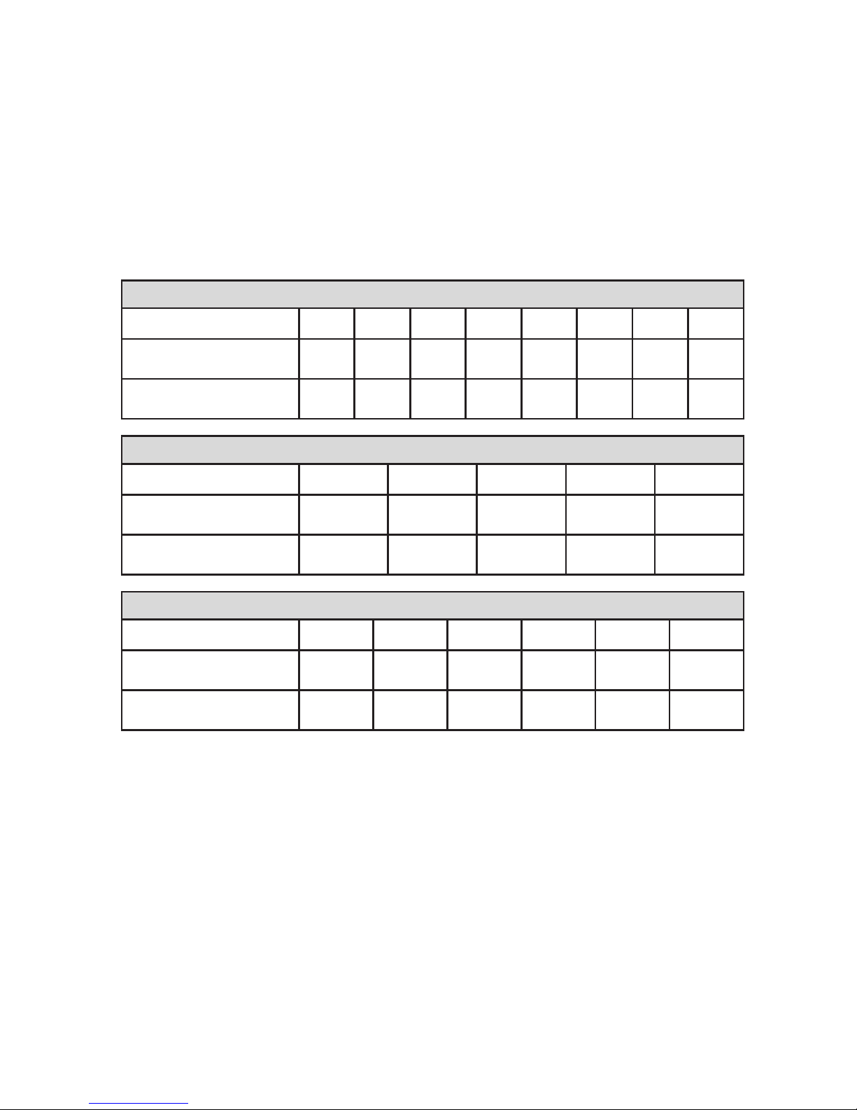
Torque Specifictions
All fasteners must be torqued to specifications. Use manufacturers’ torque values
for OEM fasteners. Apply Loctite 242 (blue) or equivlent on ll engine-mounted
fsteners. Torque values are with Loctite applied unless otherwise specified.
Stndrd Grde 8 Ntionl Corse Thred
Size (in) 1/4 5/16 3/8 7/16 1/2 9/16 5/8 3/4
Foot pounds (ft•lb) 9 18 35 55 80 110 170 280
Newton meter (N•m) 12 24 47 74 108 149 230 379
Stndrd Grde 8 Ntionl Fine Thred
Size (in) 3/8 7/16 1/2 5/8 3/4
Foot pounds (ft•lb) 40 60 90 180 320
Newton meter (N•m) 54 81 122 244 434
Metric Clss 10.9
Size (mm) M6 M8 M10 M12 M14 M16
Foot pounds (ft•lb) 4.5 19 41 69 104 174
Newton meter (N•m) 6 25 55 93 141 236
Tble 1 — Torque Tble
VMAC - Vehicle Mounted Air Compressors
VMAC Technical Support: 888-241-2289
VMAC Knowledge Base: www.kb.vmacair.com
8
Preparation for installation is very important. Missing a step
or an item can cause problems in the installation or damage to
components.
☑
Check off each item as it is completed so that no steps are
missed.
☐
Review the contents of the system using the illustrated parts list to ensure all
components are present and in the correct quantity. If any components are
missing, have the system ID ready and call VMAC Technical Support at
(888) 241-2289.
The VMAC warranty form must be completed and returned to VMAC
at the time of installation for any subsequent warranty claim to be
considered valid.
☐
Complete the warranty form. The VMAC warranty form is located at the back
of this manual, as well as online at: www.vmacair.com/warranty
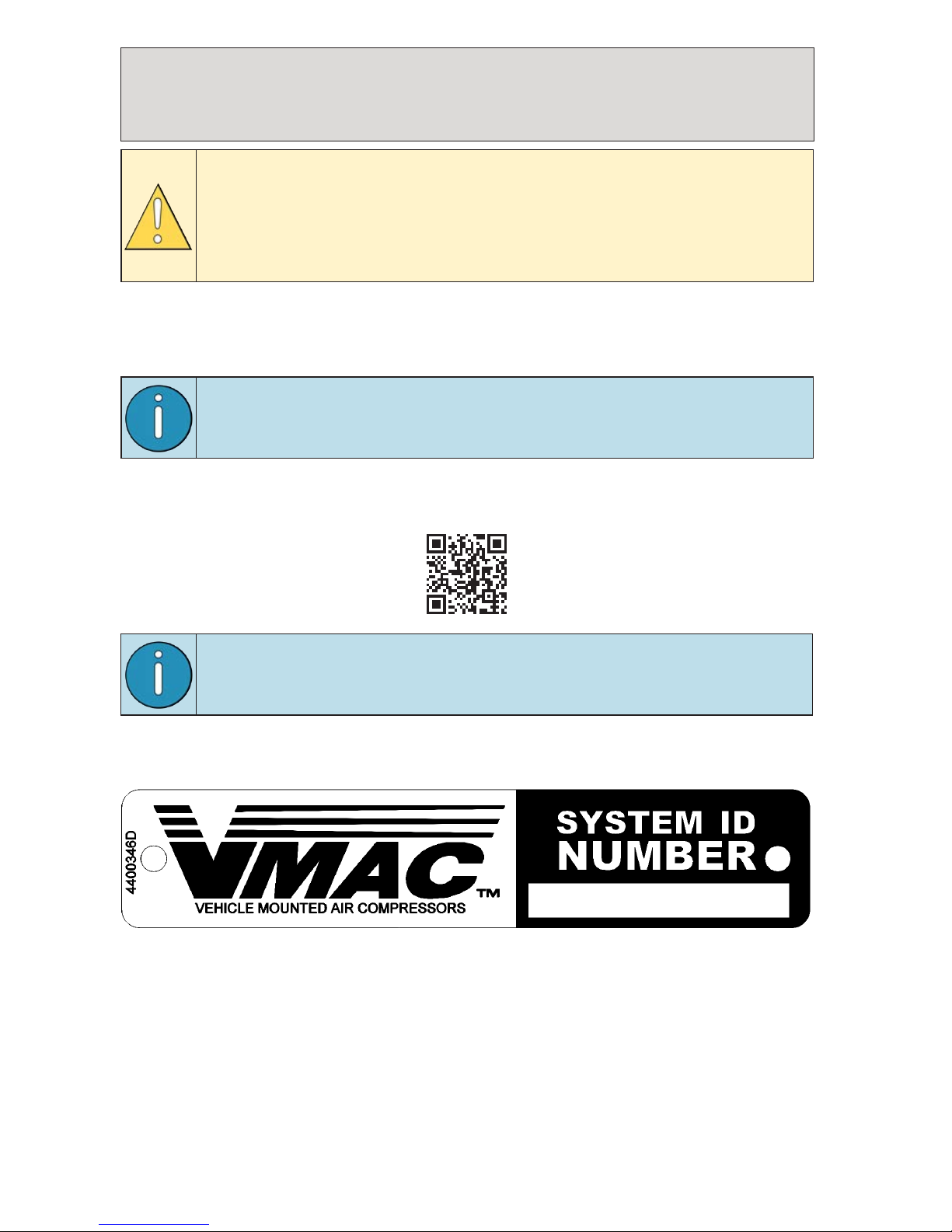
The System Identification Plate must be attached to the vehicle at
the time of installation. This plate provides information that allows
VMAC to assist with parts and repairs.
☐
Mark and drill 2 × 7/64 in holes in the top of the cross member in front of the
hood support. Secure the plate with the supplied self-tapping screws (Figure 1).
Figure 1 — System Identifiction Plte
System Identifiction, Wrrnty
Registrtion nd Wrning Lbels
VMAC - Vehicle Mounted Air Compressors
VMAC Technical Support: 888-241-2289
VMAC Knowledge Base: www.kb.vmacair.com
9
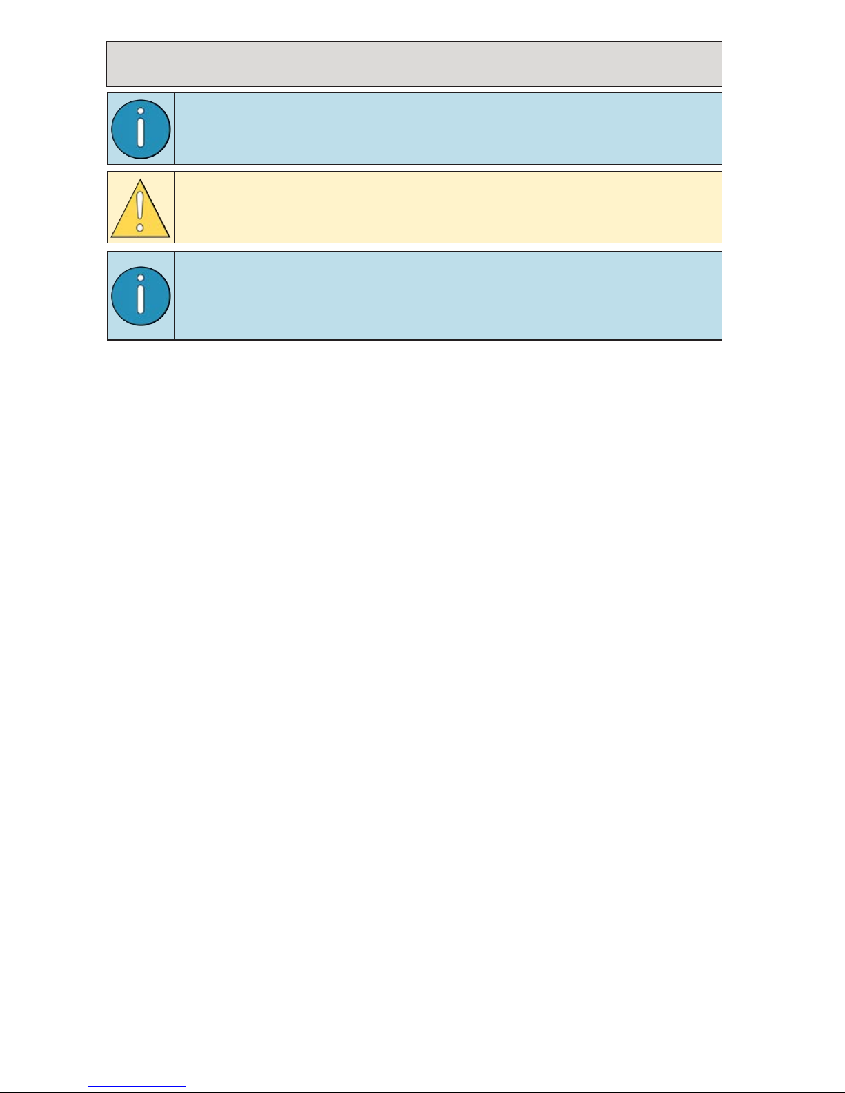
☐
As part of the installation process, ensure that the safety and operational
instruction decal is affixed in an obvious location so that it can be seen by
vehicle operators. A good spot for this is usually on the inside of the door or on
the panel underneath the steering wheel (Figure 4).
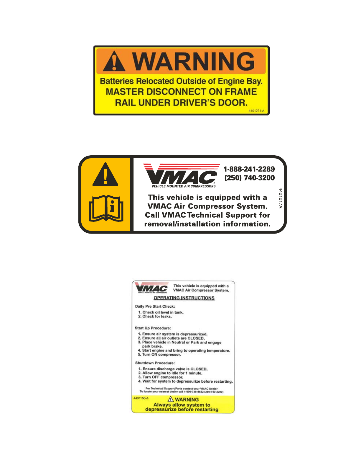
Figure 2 — Bttery reloction wrning lbel
☐
To alert any technicians that may service the vehicle, affix the servicing
caution/contact label in the engine compartment near the hood latch in a
visible location (Figure 3).
Figure 3 — Advisory lbel
☐
To alert any technicians or emergency responders that may service the vehicle
or respond to an accident, thoroughly clean the radiator cross member and
affix the battery relocation warning label in a conspicuous location (Figure 2).
Figure 4 — Operting Instruction lbel
VMAC - Vehicle Mounted Air Compressors
VMAC Technical Support: 888-241-2289
VMAC Knowledge Base: www.kb.vmacair.com
10
Ensure the VMAC Warranty Registration has been completed and
the System Identification Plate and Operating Instruction Label are
installed prior to proceeding (see page 8 for details).
Prepring for Instlltion
VMAC provides material to relocate the vehicle batteries from
the engine bay to the driver side frame rail. Depending on the
application, the end user may wish to relocate the batteries to an
alternate location (see page 49 before continuing.
Do not use a test light to probe for power on vehicle circuits, the
increased current draw of the test light may damage components.
☐
Locate the blunt-cut OEM SEIC wire harness, on the passenger side in the foot
well. Find the transmission park signal, (Grey wire with Brown stripe).
☐
Use a multi-meter to verify the transmission park signal. Turn the key to the
“IGN2” position but do not start the truck (on vehicles equipped with a “START”
button, depress the button but to not apply the service brake) to supply power
to the dash display. The resistance to ground should read close to 0 Ω in
“PARK” and open circuit in all other gears. If this is correct, put the vehicle in
“PARK” and turn the ignition “OFF”.
☐
Mark the transmission park signal wire for connection later in the “Installing the
Control Components” section.
☐
Disconnect and remove both batteries.
☐
Remove the lower bumper/air dam to improve access.
☐
Remove the top radiator cross member cover.
☐
Remove the (×8) bolts securing the grille and pull gently to remove the grille
from the vehicle.
☐
Remove the driver side headlight. The headlight is mounted with (×4) bolts, 1
bolt is hidden behind the rubber trim between the fender and the bumper.
☐
Drain the primary and secondary radiators into separate, clean containers. Set
the coolant aside for use later.
☐
Remove the intake air box and cover the engine-side port to prevent debris
entering the engine.
☐
Remove the ground strap running between the battery and the inner fender to
improve access.
☐
Remove the passenger side battery tray, intake snorkel, and lower duct
assembly.
☐
Remove the secondary coolant reservoir.
☐
Disconnect the ‘hot’ side ducting from both the turbo and the Charge Air Cooler
(CAC) and set the ducting aside for modification.
VMAC - Vehicle Mounted Air Compressors
VMAC Technical Support: 888-241-2289
VMAC Knowledge Base: www.kb.vmacair.com
11
☐
Remove the upper radiator hose and cover the ports to prevent debris
accessing the engine or coolant system.
☐
Cover the turbo and CAC ports to prevent debris entering the engine.
☐
Disconnect the rest of the CAC connections and cover the openings to prevent
debris entering the engine air intake or coolant systems.
☐
Remove the CAC.
☐
Remove the driver side battery tray and degas bottle assembly. This will not be
reused but can be retained should the vehicle be reverted to stock.
☐
Mark the washer fluid pump wire harness for modification in a later chapter.
☐
Remove the front (×3) inner fender liner bolts and pull the fender liner out of the
way to access the fasteners securing the washer fluid reservoir.
☐
Disconnect and remove the washer fluid reservoir and battery tray support
bracket.
☐
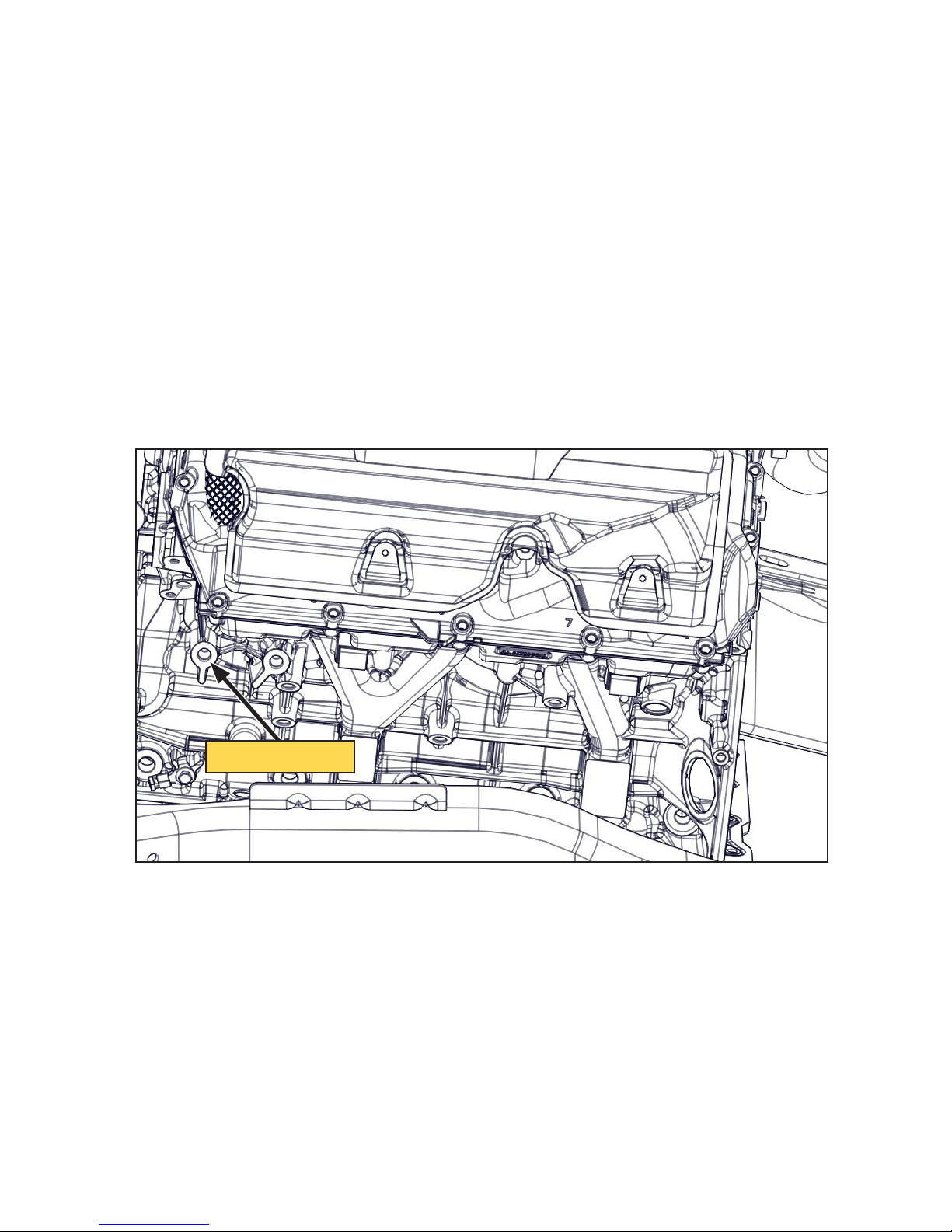
Thoroughly clean the surface around the M12 threaded hole on the front driver
side of the engine block, directly below the valve cover (Figure 5).
Figure 5 — Instlling the negtive bttery cble
Clen surfce
VMAC - Vehicle Mounted Air Compressors
VMAC Technical Support: 888-241-2289
VMAC Knowledge Base: www.kb.vmacair.com
12
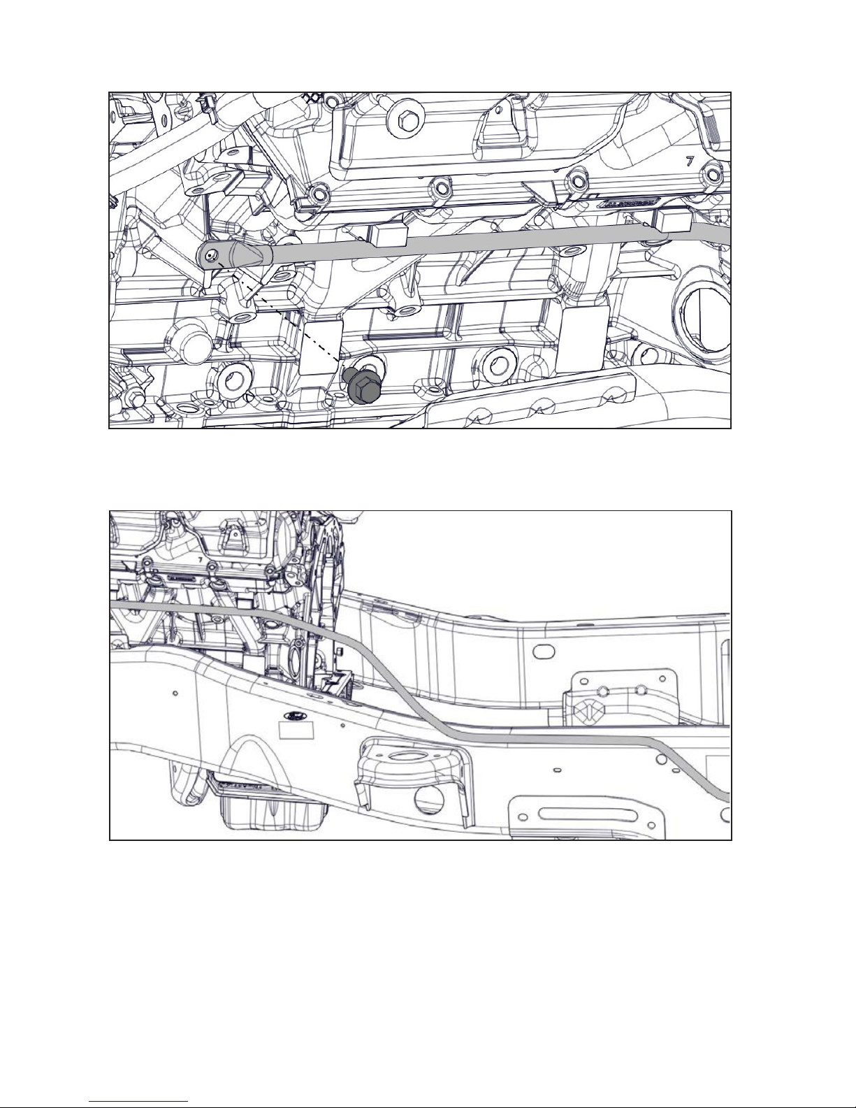
☐
Using the M12 x 1.75 x 25 bolt, attach the 1/0 AWG VMAC negative battery
relocation cable to the engine block (Figure 6).
Figure 6 — Instlling the negtive bttery cble
☐
Route the cable along the engine, crossing to the outside of the frame just after
the forward body mount. Installation will continue later in the manual (Figure 7).
Figure 7 — Routing the negtive bttery
☐
Reinstall the inner fender liner bolts.
☐
Remove the inner fender clip nut from the driver side battery tray support
bracket and set aside for later.
☐
Drain the washer fluid into a clean receptacle and retain for use later.
☐
The washer fluid reservoir and battery tray support bracket will not be reused
but can be retained should the vehicle be reverted to stock.
VMAC - Vehicle Mounted Air Compressors
VMAC Technical Support: 888-241-2289
VMAC Knowledge Base: www.kb.vmacair.com
13
☐
Keeping the power steering lines connected, remove the power steering
reservoir from the driver side of the fan shroud.
☐
Temporarily tie the power steering reservoir up and out of the way of the
shroud.
The power steering reservoir cap will leak if the reservoir is not kept
upright.
☐
Remove the upper radiator shroud.
☐
Disconnect the radiator fan harness and remove and discard the OEM bolt
(Figure 8).
Figure 8 — Disconnect fn hrness
Discrd OEM
fstener
☐
Remove the fan and harness assembly using a pneumatic fan wrench (such as
Lisle 43300).
☐
Remove the fan shroud stator.
☐
Remove the OEM FEAD belt.
☐
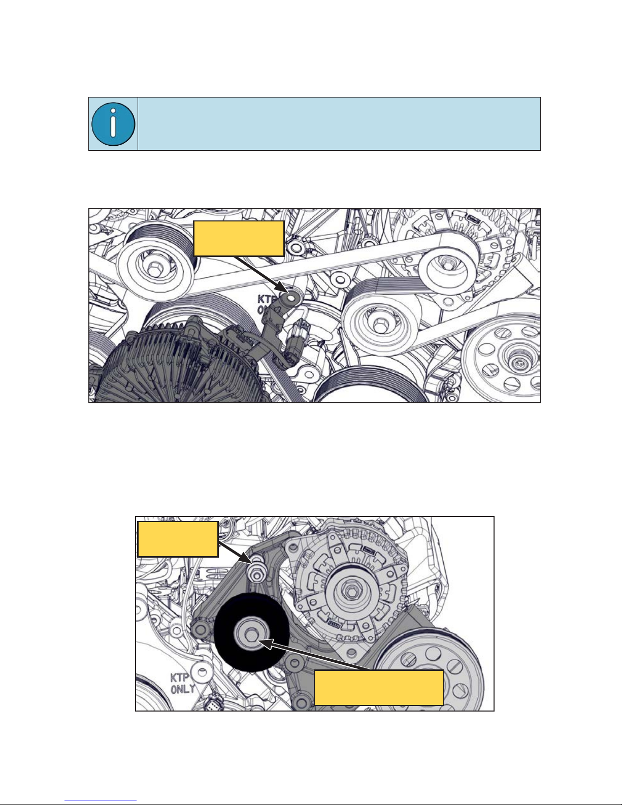
Remove the primary alternator (Figure 9).
Figure 9 — OEM lterntor nd power steering brcket
Remove
shroud post
Note loction nd
remove OEM idler
VMAC - Vehicle Mounted Air Compressors
VMAC Technical Support: 888-241-2289
VMAC Knowledge Base: www.kb.vmacair.com
14
On vehicles equipped with adaptive power steering, removing the
power steering pump pulley will improve access to the fasteners.
Do not remove the power steering fluid lines from the power
steering pump.
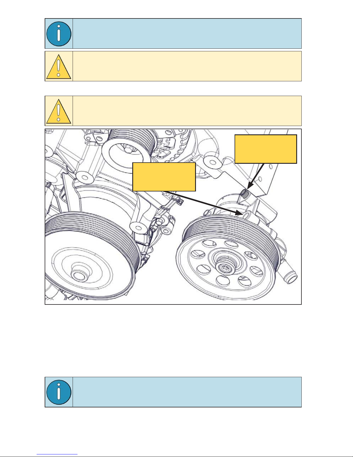
For vehicles equipped with the optional “Adaptive Power Steering”
power steering pump, relocate the upper rear bushing to the upper
forward mount position (Figure 10).
Figure 10 — Adptive power steering pump
☐
Unbolt the power steering pump and secure it out of the way.
Adptive power
steering bushing
(OEM loction)
Adptive power
steering bushing
(VMAC loction)
☐
Take note of the location of the OEM idler on the power steering pump /
primary alternator bracket.
☐
Remove the OEM idler from the bracket (Figure 9).
☐
Remove the fan shroud stator post from the OEM bracket (Figure 9).
☐
Remove the OEM alternator / power steering pump bracket from the engine.
This will not be reused but may be retained.
Remove the (×4) rubber bushings from the main bracket bolt holes
and set aside for later.
VMAC - Vehicle Mounted Air Compressors
VMAC Technical Support: 888-241-2289
VMAC Knowledge Base: www.kb.vmacair.com
15
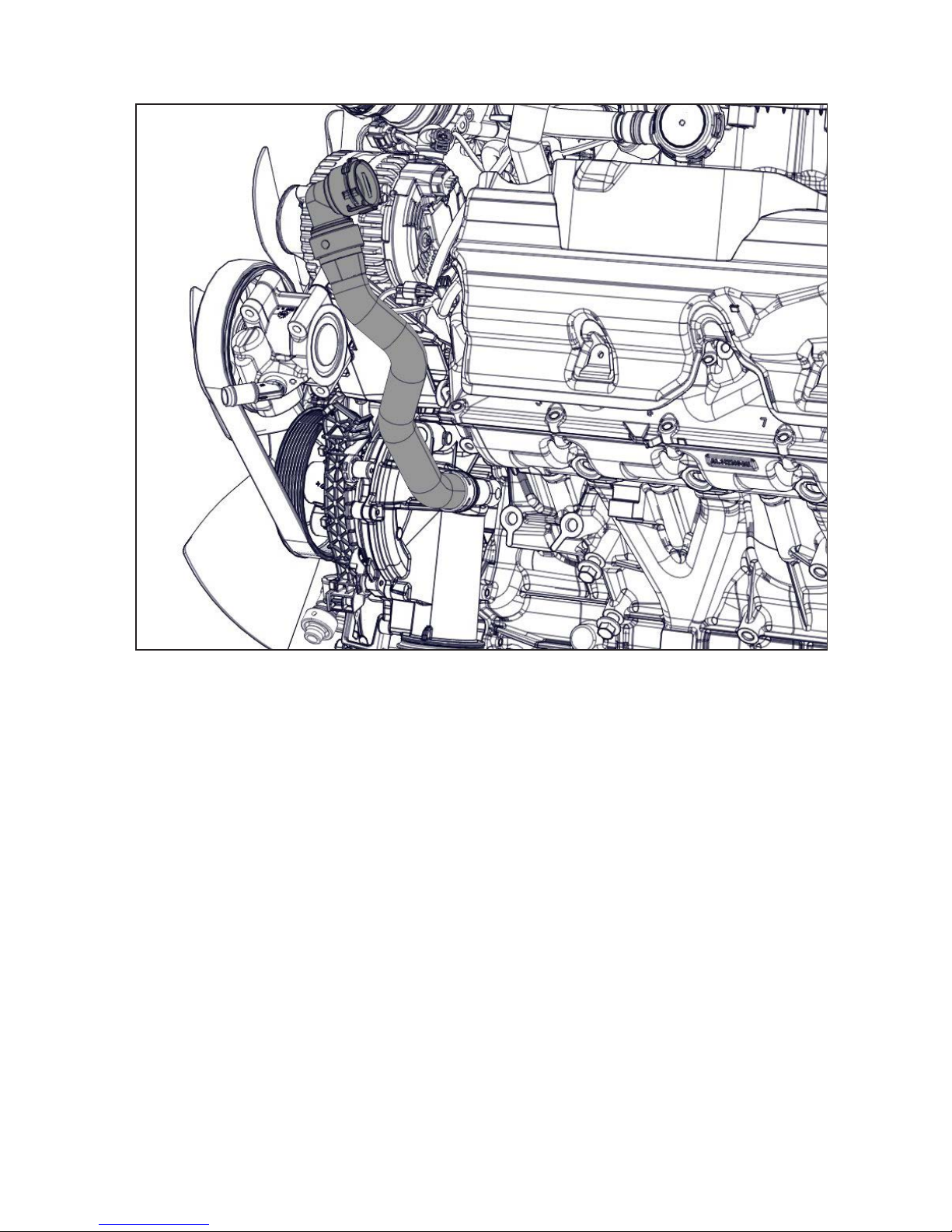
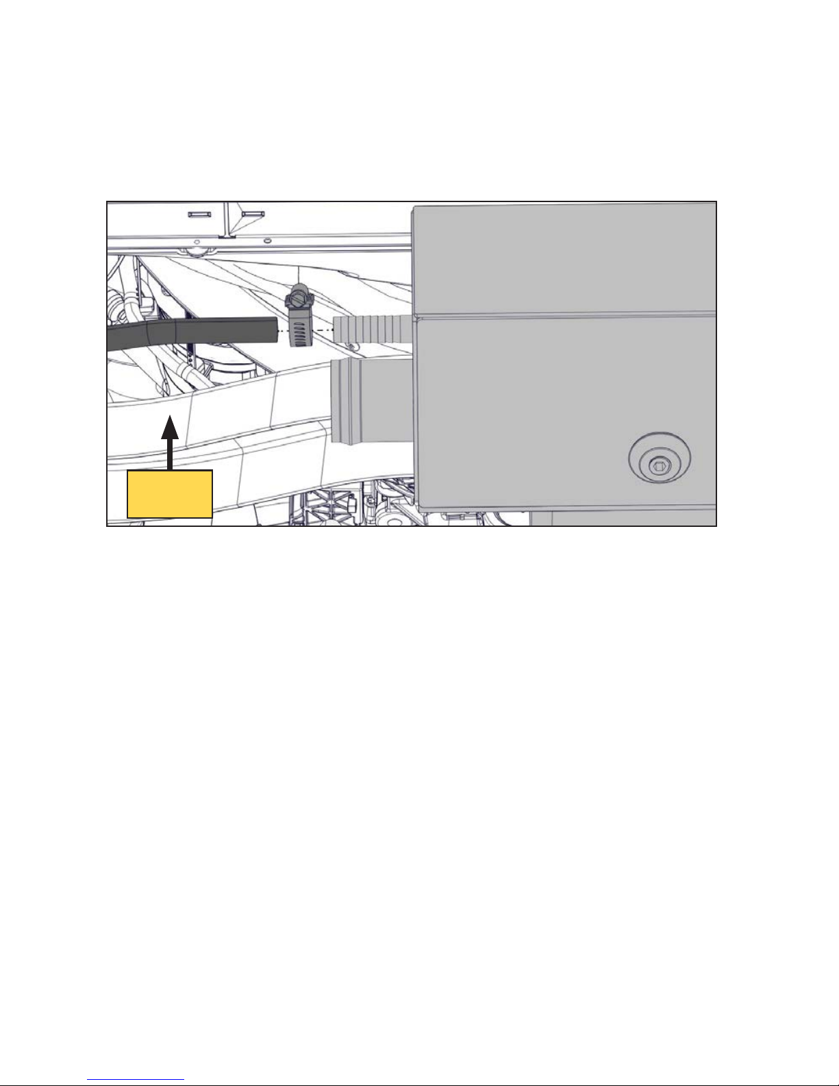
☐
Remove the primary drain-back hose running between the engine and the OEM
degas bottle (Figure 11).
Figure 11 — Remove the primry drin-bck hose
VMAC - Vehicle Mounted Air Compressors
VMAC Technical Support: 888-241-2289
VMAC Knowledge Base: www.kb.vmacair.com
16
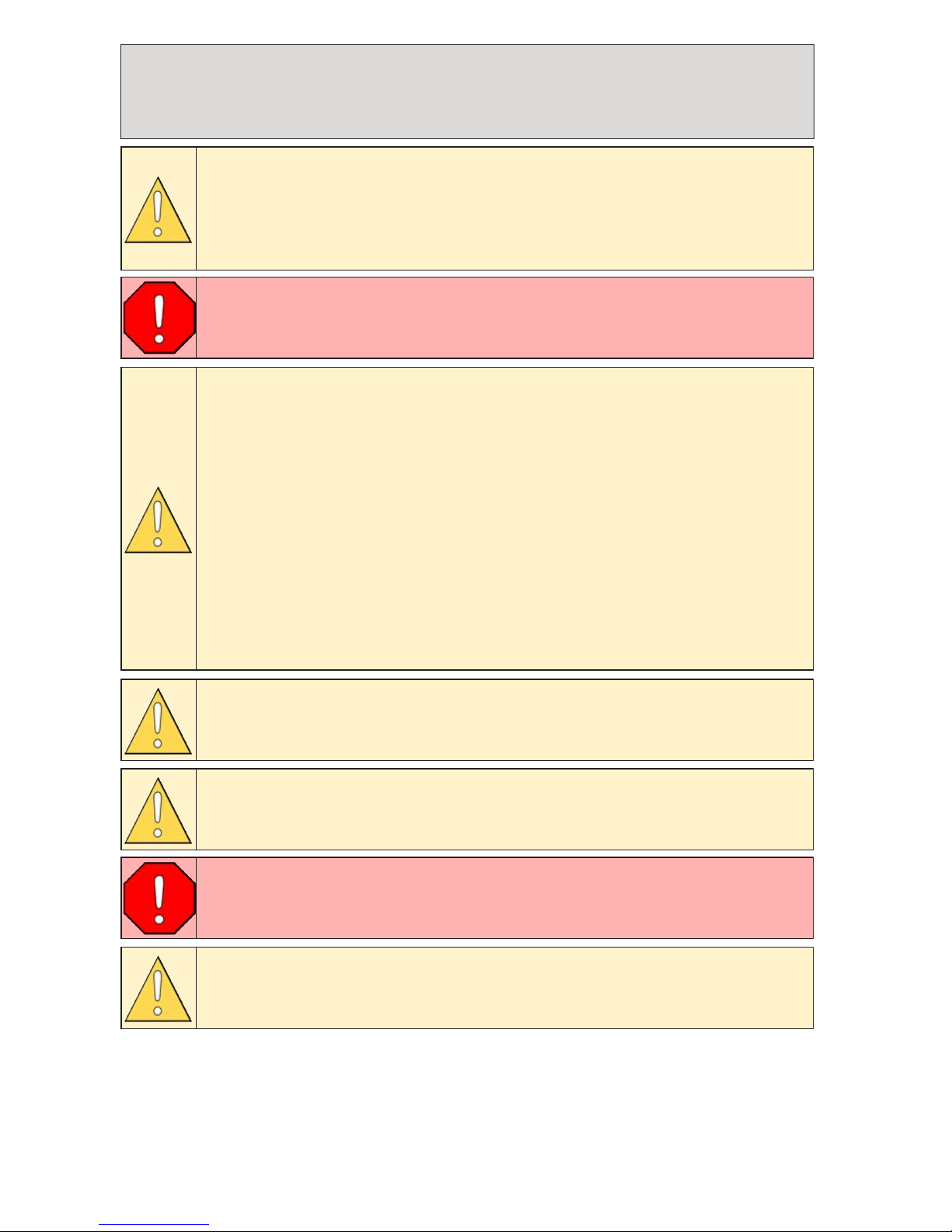
Relocting the ABS Hydrulic Control
Unit (HCU)
Depending on the application, the following steps may not be
necessary. If the HCU is mounted towards the firewall
(Figure 15 on page 18), proceed to the next chapter. If the HCU
bracket is mounted using the holes shown in Figure 12, follow the
steps in this chapter.
Failure to follow these instructions may result in brake system
contamination, component damage and/or death.
It may be necessary to rotate the brake lines that connect the
master cylinder to the ABS HCU module to avoid kinking the flexible
rubber hoses as the HCU is shifted to its new position. The following
process will help to avoid air from entering the brake system as
brake fluid is forced out of the system.
Do not pump the brakes at any time while the brake lines are loose
as air may be drawn into the system.
Have an assistant gently depress the service brake as the brake
line is loosened, rotated into a relaxed position and then quickly
re-tightened. Adjust one brake line at a time. If there is a significant
amount of brake fluid escaping from the fitting, the pedal is being
pressed too hard and/or the fitting has been loosened too much.
Do not allow the brake master cylinder to run dry during these
steps. The master cylinder may be damaged if operated without
fluid.
Use only clean brake fluid from an unopened container that meets
Ford specifications.
If there is any concern that air may have entered the brake system,
consult a local Ford dealer or licensed repair facility for vehicle
specific HCU brake bleeding instructions.
Apply Loctite 242 (blue) to all engine mounted fasteners.
VMAC - Vehicle Mounted Air Compressors
VMAC Technical Support: 888-241-2289
VMAC Knowledge Base: www.kb.vmacair.com
17
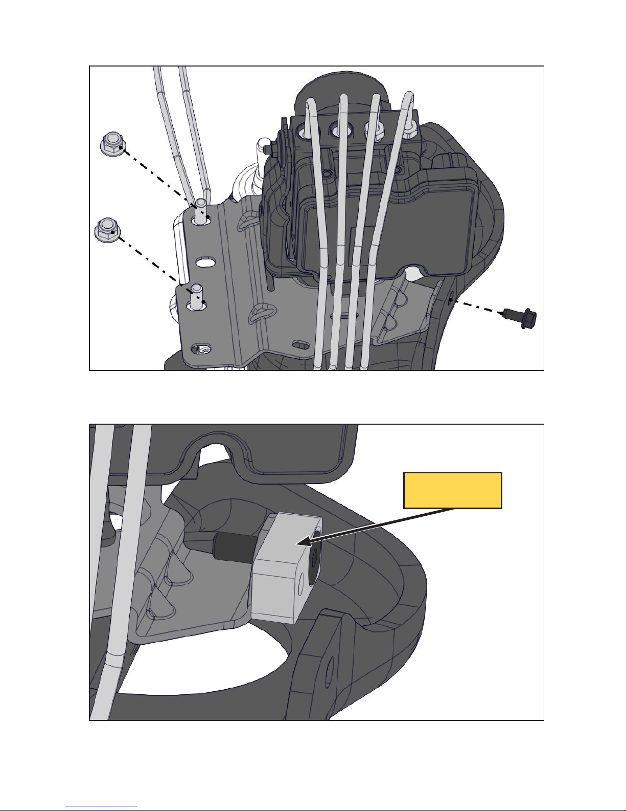
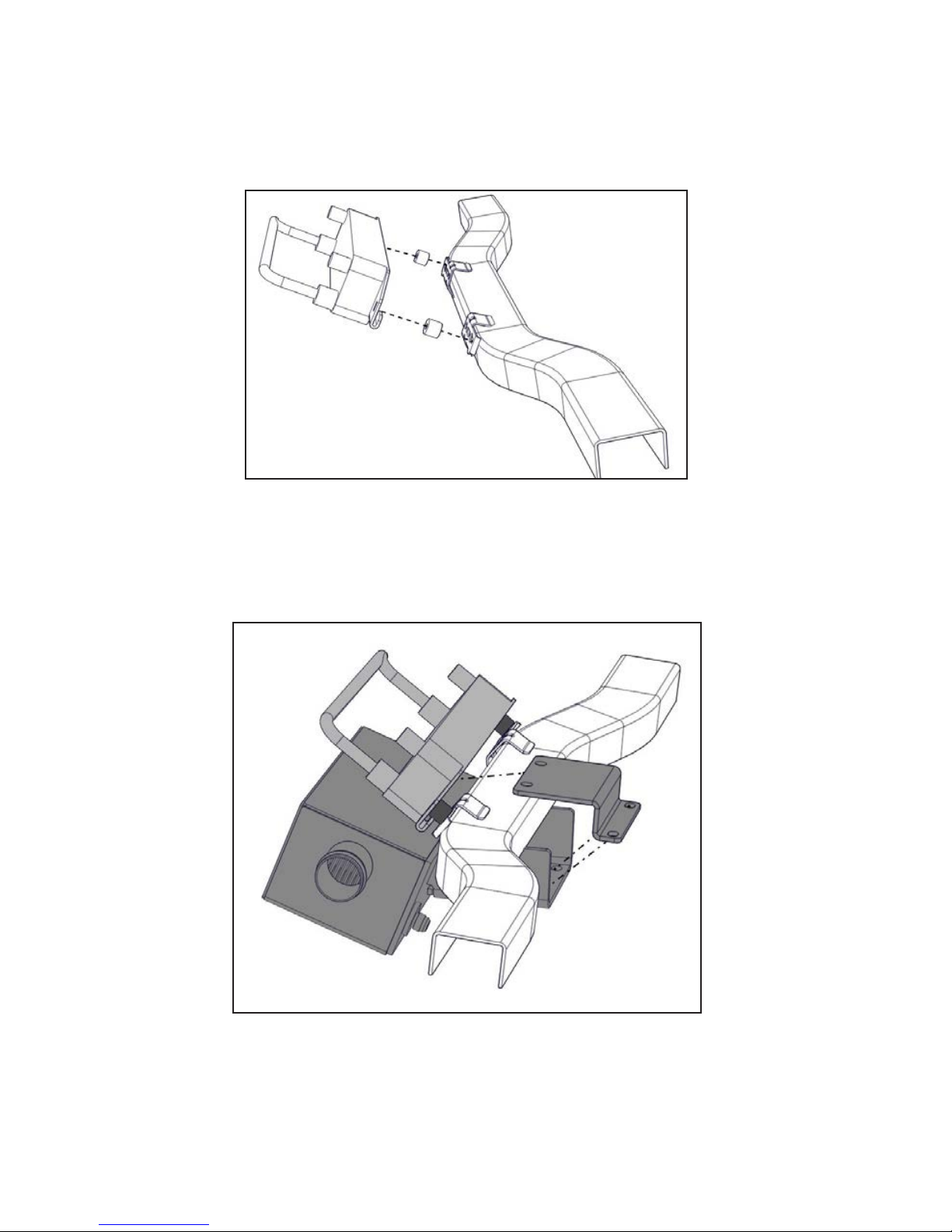
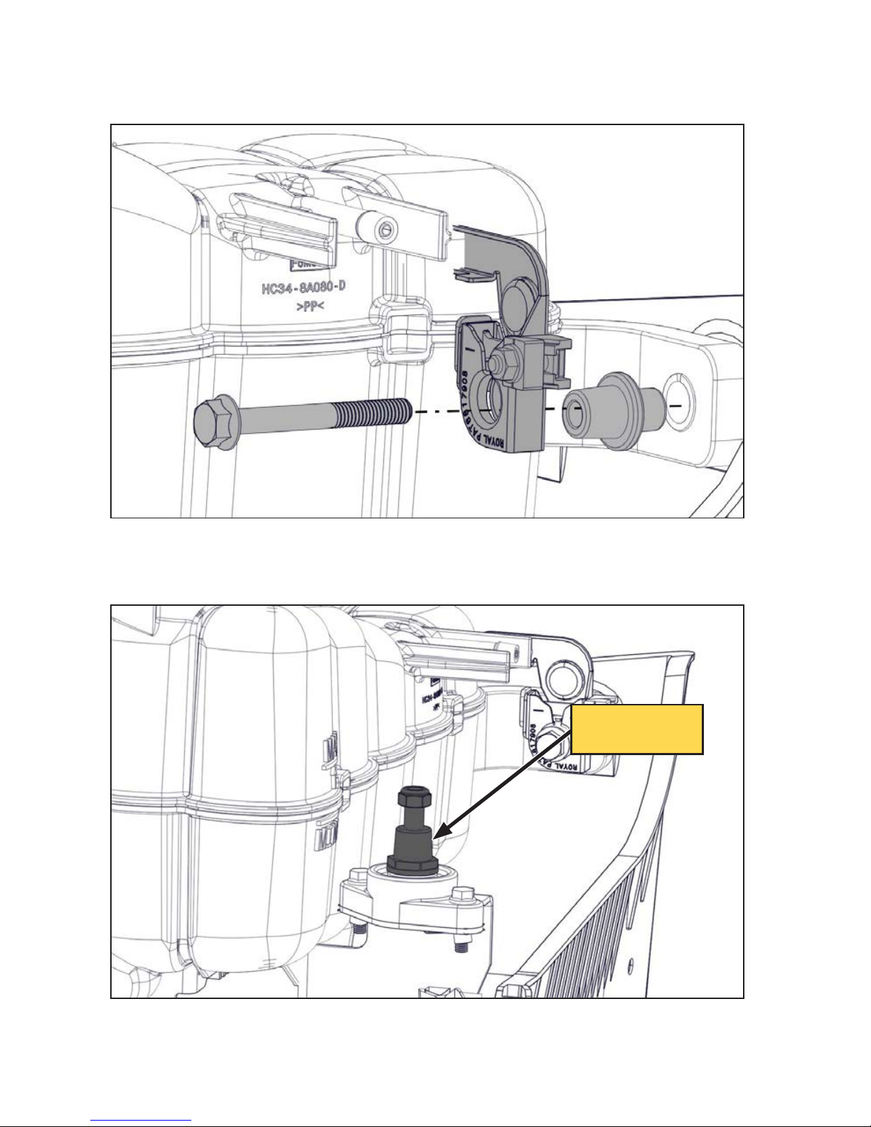
Figure 12 — Relocting the HCU
☐
Remove the bolt and (×2) nuts securing the HCU and lift it clear of the shock
tower (Figure 12).
☐
Apply Loctite 242 (blue) to the supplied flat head fastener and install the
supplied HCU relocation bracket (Figure 13).
Figure 13 — Relocting the HCU
HCU reloction
brcket
VMAC - Vehicle Mounted Air Compressors
VMAC Technical Support: 888-241-2289
VMAC Knowledge Base: www.kb.vmacair.com
18
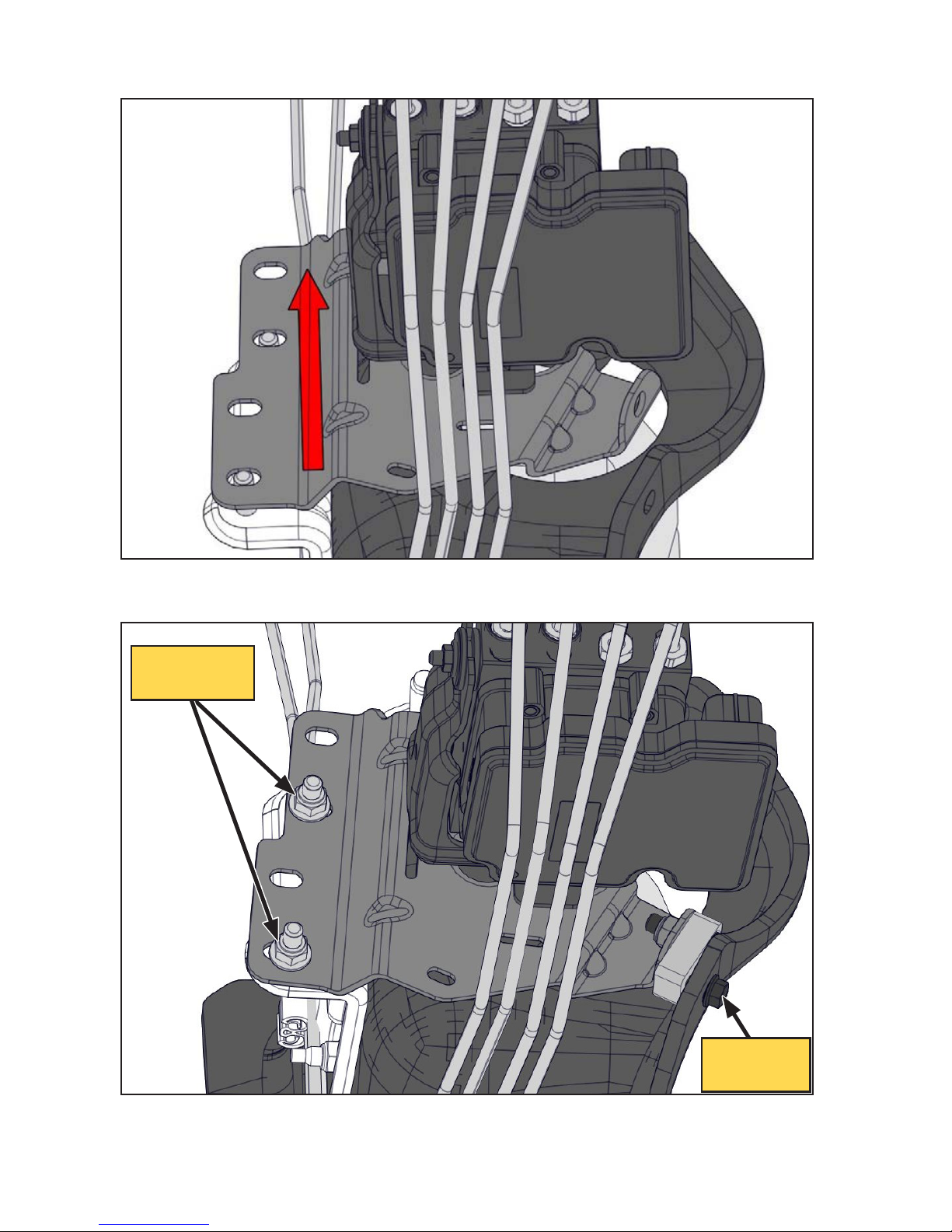
☐
Gently shift the HCU towards the firewall taking care not to bend or kink the
brake lines. Align the bracket with the second set of mounting holes (Figure 14).
☐
Install the bolt and (×2) nuts (Figure 15).
Figure 14 — Relocting the HCU
Figure 15 — Relocting the HCU
Reinstll
both nuts
Reinstll
bolt
VMAC - Vehicle Mounted Air Compressors
VMAC Technical Support: 888-241-2289
VMAC Knowledge Base: www.kb.vmacair.com
19
Modifying the Hoses, Instlling the
Cooler
Modifying the Coolnt Hoses
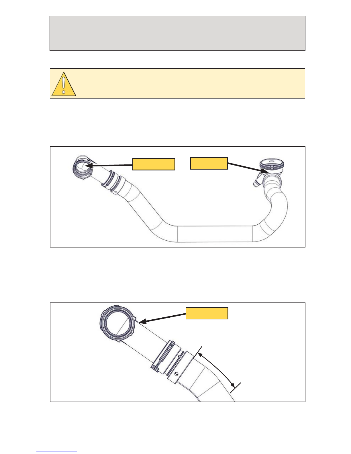
Figure 16 — Lower rditor hose
To engine
To rditor
☐
Roll the OEM anti-abrasion mesh up towards the radiator side quick connect as
this will be retained on the hose.
☐
From the OEM quick connector cuff on the radiator side of the hose, measure
4 1/2 in along the outside radius towards the center of the hose and mark with
a grease pen (Figure 17).
Figure 17 — Lower rditor hose modifiction
4 1/2 in
To rditor
Apply Loctite 242 (blue) to all engine mounted fasteners.
Optional: Removing the passenger side inner fender will improve access to the
lower radiator hose.
☐
Remove passenger side inner fender.
☐
Uncouple the lower radiator hose assembly at the engine and radiator and
remove the assembly from the engine bay (Figure 16).

VMAC - Vehicle Mounted Air Compressors
VMAC Technical Support: 888-241-2289
VMAC Knowledge Base: www.kb.vmacair.com
20
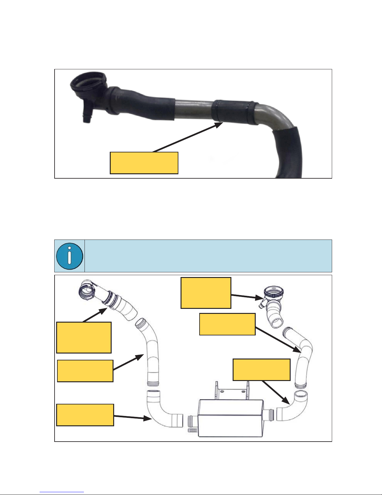
☐
From the OEM quick connector cuff on the engine side of the hose, measure
6 in along the outside radius towards the center of the hose and mark with a
grease pen (Figure 18).
Figure 18 — Lower rditor hose modifiction
90°
6 in
To engine
☐
Cut the radiator hose in the two marked locations, ensuring that cuts are
square to the hose section.
☐
Install the modified radiator side of the lower radiator hose onto the radiator.
☐
Install the modified engine side of the lower radiator hose onto the engine.
☐
Remove the anti-abrasion sleeve from the center section of the lower radiator
hose and slide it over the radiator side coolant tube; securing it in place with
cable ties (Figure 19).
Figure 19 — Rditor side nti-brsion sleeve
(Coolant assembly removed from vehicle for clarity)
Mesh brsion
sleeve
VMAC - Vehicle Mounted Air Compressors
VMAC Technical Support: 888-241-2289
VMAC Knowledge Base: www.kb.vmacair.com
21
☐
Cut a straight 6 in section of the discarded lower radiator hose and slit it
lengthwise. This will be used as an anti-abrasion sleeve on the driver side
coolant tube.
☐
Wrap the 6 in section around the straight section of the driver side coolant
tube and secure with cable ties (Figure 20).
☐
Remove the studs securing the vehicle transmission cooler in place and discard.
☐
Route the engine side coolant tube (P/N: 1720719) up between the crossmember
and the radiator support on the driver side of the vehicle and insert it into the
modified radiator hose near the engine (Figure 21).
If necessary, gently deflect the transmission cooler lines aside to
create sufficient clearance for the coolant tube
Figure 20 — Engine side nti-brsion sleeve
(System removed from vehicle for clarity)
6 in coolnt hose
brsion sleeve
Figure 21 — VMAC cooler ssembly
Modified
rditor side
OEM hose
Modified
engine side
OEM hose
Coolnt tube
P/N: 1720719
Coolnt elbow
P/N: 1710878
Coolnt tube
P/N: 1720718
Coolnt elbow
P/N: 1710658
VMAC - Vehicle Mounted Air Compressors
VMAC Technical Support: 888-241-2289
VMAC Knowledge Base: www.kb.vmacair.com
22
Figure 22 — Relocte the trnsmission cooler
☐
Route the radiator side coolant tube (P/N: 1720718) up between the
crossmember and the radiator support on the passenger side of the vehicle and
insert it into the modified radiator hose. The end with the sharpest bend goes
toward the radiator (Figure 21 on page 21 ).
☐
Reinstall the transmission cooler using the supplied spacers and fasteners
(Figure 22).
Instlling the Cooler
☐
Position the cooler in the center of the crossmember and slide the cooler
mount bracket over the crossmember, bolt in place using the supplied
fasteners (Figure 23).
Figure 23 — VMAC cooler instlltion
☐
Install the longer elbow to the radiator (passenger) side of the cooler and the
shorter elbow to the engine (driver) side.
☐
Attach the coolant tubes to the elbows.
VMAC - Vehicle Mounted Air Compressors
VMAC Technical Support: 888-241-2289
VMAC Knowledge Base: www.kb.vmacair.com
23
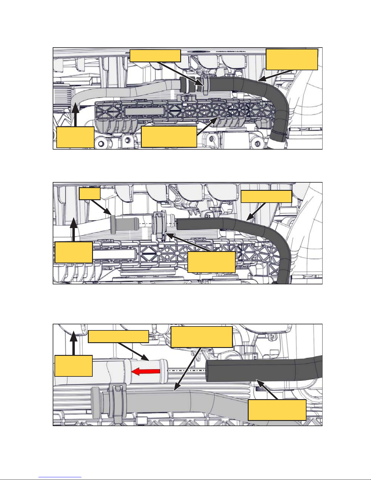
☐
Disconnect the small flexible hose secured to the cable run tray on the front of
the engine, above the steering linkage, from the metal coolant tube. Retain the
OEM spring clamp (Figure 24).
Figure 24 — Disconnect the heter return hose
Retin clmp
Disconnect
flexible hose
Cble run
(for reference)
Front of
vehicle
☐
Insert the supplied aluminum plug into the flexible hose section and secure
using the OEM spring clamp (Figure 25).
☐
Connect one end of the supplied hose to the metal coolant tube. Ensure the
hose is seated against the bead in the OEM hard line and secure using a hose
clamp (Figure 26).
Figure 25 — Plug the flexible hose
Front of
vehicle
Plug
Flexible hose
OEM spring
clmp
Figure 26 — Plug the flexible hose
Front of
vehicle
VMAC supplied
Flexible hose
OEM hrd hose
OEM flexible
hose (plugged)
VMAC - Vehicle Mounted Air Compressors
VMAC Technical Support: 888-241-2289
VMAC Knowledge Base: www.kb.vmacair.com
24
☐
Secure the plugged OEM flexible hose to the metal coolant tube using a cable
tie.
☐
Route the supplied hose forward, following the path of the larger coolant tubes
past the frame crossmember and over the cooler towards the passenger side of
the vehicle.
☐
Connect the hose to the small spigot on the passenger side of the cooler using
a hose clamp (Figure 27).
Figure 27 — Connect hose to VMAC cooler
Front of
vehicle
☐
Ensure the hose is not kinked and is secured away from any hot, sharp or
moving components.
☐
Adjust all connections as necessary to confirm that all joints are engaged
securely and that there are no twists, kinks or pinches.
☐
Secure all the connections with the supplied hose clamps.
VMAC - Vehicle Mounted Air Compressors
VMAC Technical Support: 888-241-2289
VMAC Knowledge Base: www.kb.vmacair.com
25
Modifying nd Instlling the Pssenger
Side Bttery Try, Air Intke nd VMAC
Degs Bottle
Modifying the pssenger side bttery try
☐
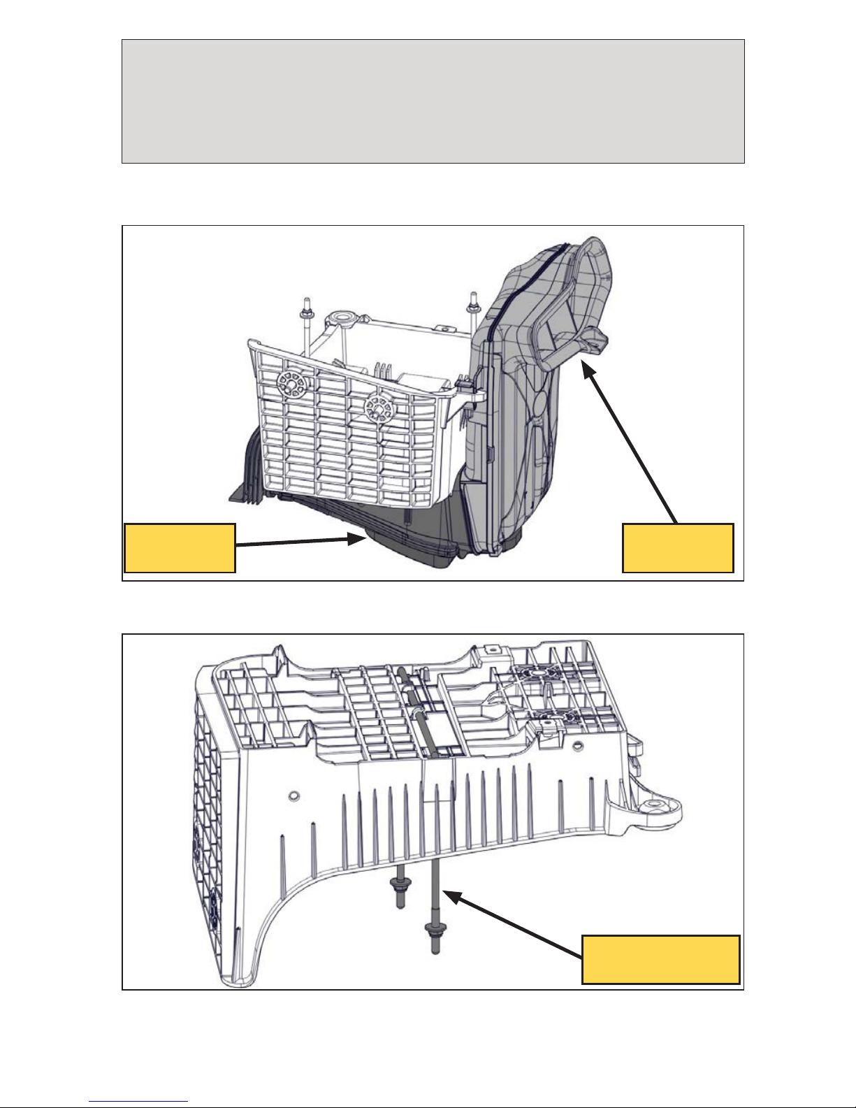
Remove the snorkel and lower duct assembly from the battery tray (Figure 28).
☐
Remove the battery hold down U-bolt. This will not be reused (Figure 29).
Figure 28 — Prepring the bttery try
Figure 29 — Prepring the bttery try
Remove
lower duct
Remove
snorkel
Remove bttery
hold down U-bolt
VMAC - Vehicle Mounted Air Compressors
VMAC Technical Support: 888-241-2289
VMAC Knowledge Base: www.kb.vmacair.com
26
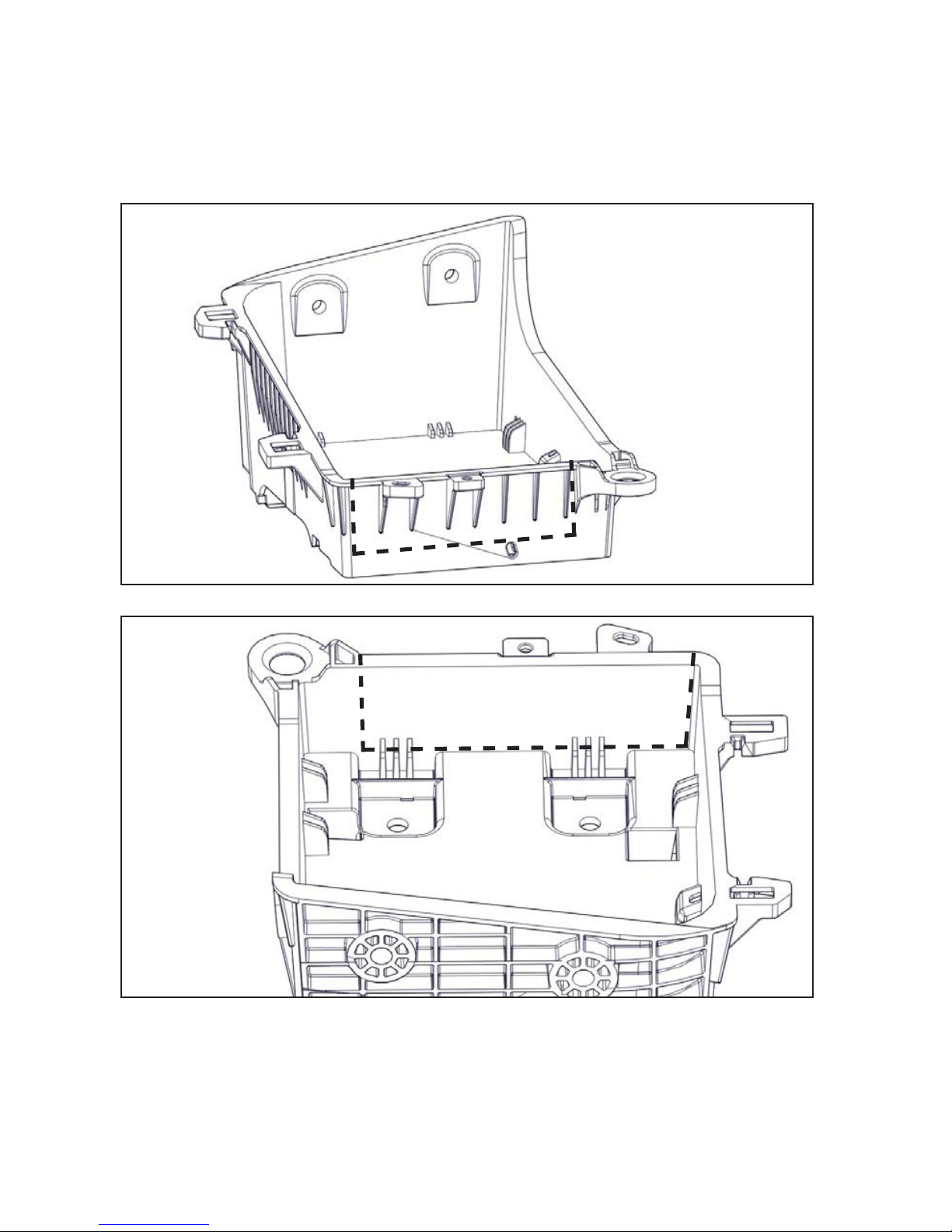
☐
Mark a cut line from the engine side battery tray mount, down to the base of
the battery tray (Figure 30, Figure 31).
☐
Continue the cut line along the base of the of the battery tray (Figure 30,
Figure 31).
☐
Mark a vertical cut line along the forward side of the engine face of the battery
tray (Figure 30, Figure 31).
☐
Cut the tray along the marked lines. Deburr any rough edges.
☐
Re-assemble the snorkel and lower duct assembly onto the battery tray.
☐
Reinstall the modified battery tray assembly into the vehicle.
Figure 30 — Modifying the bttery try
Figure 31 — Modifying the bttery try
VMAC - Vehicle Mounted Air Compressors
VMAC Technical Support: 888-241-2289
VMAC Knowledge Base: www.kb.vmacair.com
27
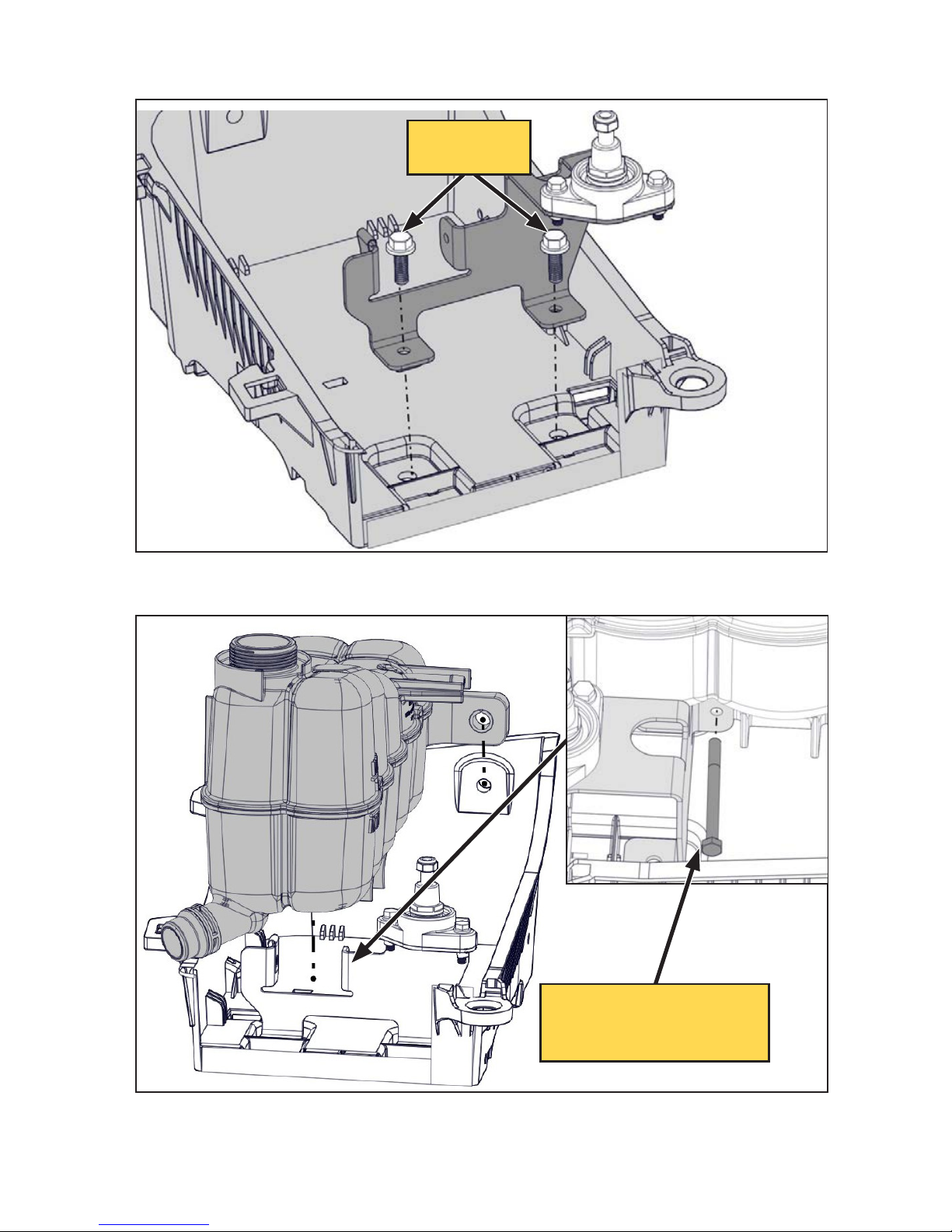
☐
Install the VMAC degas bottle and battery post relocation bracket into the
modified battery tray (Figure 32).
☐
Install and secure the VMAC degas bottle to the bracket. (Figure 33).
Figure 32 — Instlling the degs bottle brcket
Figure 33 — Instlling the degs bottle
VMAC
fsteners
Leve loose until fter
negtive terminl is
connected, then tighten
VMAC - Vehicle Mounted Air Compressors
VMAC Technical Support: 888-241-2289
VMAC Knowledge Base: www.kb.vmacair.com
28
Pssenger side bttery reloction
☐
Install the OEM negative battery terminal using the supplied post and fastener.
(Figure 34).
☐
Reinstall the ground strap to the inner fender.
☐
Install the passenger side OEM positive battery cable (Figure 35).
Figure 34 — Instlling the negtive bttery terminl
Figure 35 — Instlling the positive bttery cble
Instll positive
bttery cble
 Loading...