

Vmac PREDATAIR60 Installation Manual

VMAC – Vehicle Mounted Air Compressors
Toll Free: 1-800-738-8622 Local: 1-250-740-3200
Fax: 1-250-740-3201
1
Installation Manual
PREDATAIR60
Hydraulic Compressor
1.0 General Information ...................................................................3
1.1 Specifications and Components ...............................................3
2.0 Installation Requirements..........................................................6
2.1 Ventilation Requirements..........................................................6
2.2 Hydraulic Requirements..........................................................11
2.3 Electrical Requirements ..........................................................12
2.4 Air Receiver Requirements .....................................................13
3.0 Installing the PREDATAIR60 ...................................................15
3.1 Mounting the Compressor.......................................................15
3.2 Connecting the Wiring.............................................................15
3.3 Speed Control .........................................................................20
4.0 Completing the Installation .....................................................23
4.1 Before Operation Checklist .....................................................23
4.2 After Engaging the Hydraulics Checklist.................................23
4.3 Setup, Performance Testing and Adjustments .......................24
5.0 Testing Ventilation ...................................................................26
5.1 Calculating Duty Cycle............................................................26
5.2 Testing the Installation ............................................................28
5.3 Analyzing the Test Results .....................................................31
6.0 Hydraulic System Data.............................................................34
6.1 Hydraulic Oil Type...................................................................34
6.2 Hydraulic Line Sizing ..............................................................35
6.3 Hydraulic System Filtration .....................................................40
6.4 Hydraulic Oil Reservoir ...........................................................40
6.5 Avoiding Cavitation .................................................................44
Ordering Parts.................................................................................44

VMAC – Vehicle Mounted Air Compressors
Toll Free: 1-800-738-8622 Local: 1-250-740-3200
Fax: 1-250-740-3201
2
Document #1930125
Installation Manual for VMAC System H600001
PREDATAIR60 Hydraulic Compressor
Changes and Revisions
Version Revision Details Revised by/date Approved Implemented
00 Original manual IB June 16 2006 SM 25 Aug 2006 28 Aug 2006
Important Information
The information in this manual is intended for certified VMAC
installers who have been trained in installation procedures and for
people with mechanical trade certification who have the tools and
equipment to properly and safely perform the installation. Do not
attempt this installation if you do not have the appropriate
mechanical training, knowledge and experience.
Follow all safety precautions for mechanical work. If you have
difficulty with the installation, contact VMAC.
The VMAC warranty form is located at the back of this manual. This
warranty form must be completed and mailed or faxed to VMAC at
the time of installation for any subsequent warranty claim to be
considered valid.
To order parts, contact your VMAC dealer. Your dealer will ask for
the VMAC serial number, part number, description and quantity. To
locate your nearest dealer, call 1-800-738-8622.
Copyright 2006
All trademarks used in this manual are the property of the respective copyright holder.
The contents of this manual may not be reproduced in any form without the express
written permission of VMAC, 1333 Kipp Road, Nanaimo, BC V9X 1R3.
Printed in Canada

VMAC – Vehicle Mounted Air Compressors
Toll Free: 1-800-738-8622 Local: 1-250-740-3200
Fax: 1-250-740-3201
3
1.0 General Information
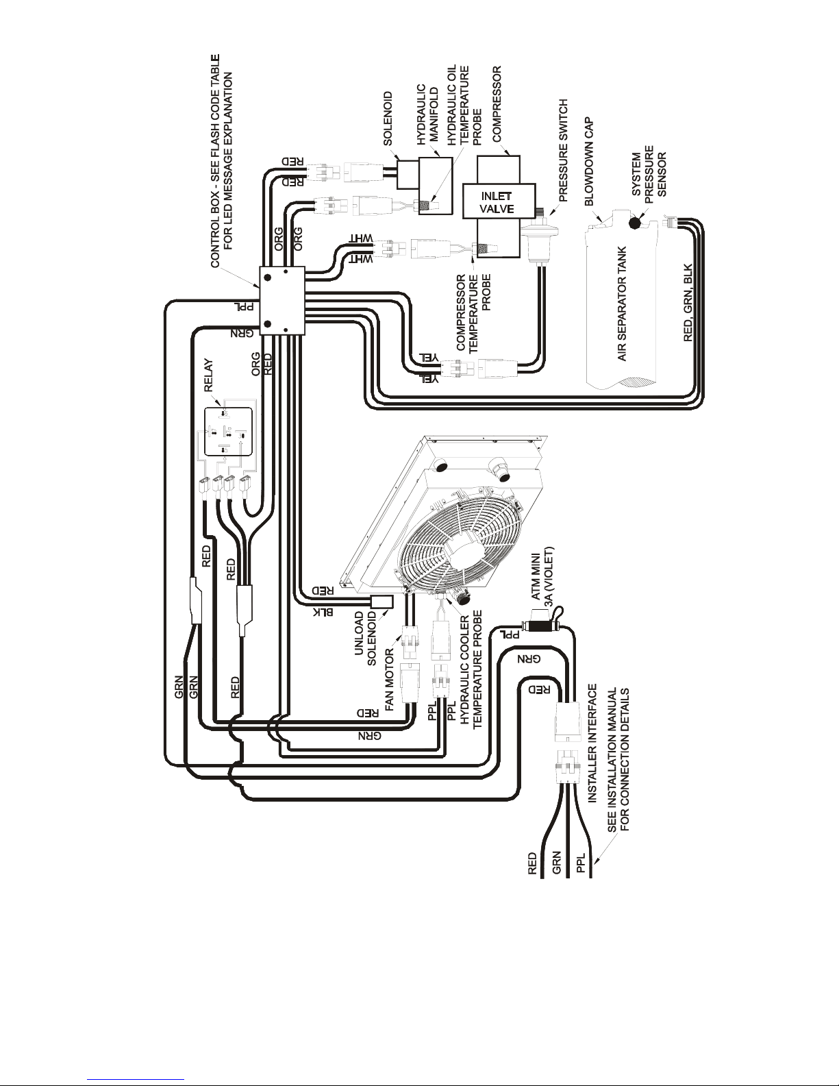
Read this manual before beginning the installation so that you can
understand the hydraulic, electric (Figure 2) and ventilation
requirements. This will ensure a successful installation and effective
operation of the PREDATAIR60 (Figure 1).
1.1 Specifications and Components
This is a flooded-lobe, rotary screw compressor (filled with VMAC
certified and approved synthetic oil) driven by a hydraulic motor.
Compression occurs when inlet air (at normal atmospheric pressure)
enters a chamber where it is trapped between the rotating rotor
lobes. A lubricated pitch line provides sealing. As the lobes mesh,
they reduce the volume of the air, compressing it to the desired
pressure.
The system has a two-stage air/oil separator. The first separation
stage consists of baffles, which perform mechanical separation. The
second stage uses a special separation element, which delivers dry
air to the outlet.
Pressure regulation is achieved with a mechanical inlet control valve
and an adjustable pressure regulator.
The compressor is protected by a paper-type replaceable air filter
and a spin-on type oil filter. Oil is removed from the delivered service
air by a coalescing separator element.
Safety features include:
• 2,650 psi hydraulic pressure relief valve
• 200 PSI relief valve in oil/air tank
• blow-down valve to discharge system pressure on shutdown
• temperature safety sensor in compressor
Do not disable or bypass the over-temperature
shutdown circuit. Failure of the shutdown system could
result in equipment damage, injury or death.
A liquid-to-air cooler maintains operating temperatures in an optimal
performance range which increases system durability and reduces
the temperature of the compressed air.
The system pressure is pre-set at 150 psi. Do not increase this
pressure setting as it will also increase the hydraulic operating
pressure. To reduce the pressure, use a Filter Regulator Lubricator
(FRL).
!
VMAC – Vehicle Mounted Air Compressors
Toll Free: 1-800-738-8622 Local: 1-250-740-3200
Fax: 1-250-740-3201
4
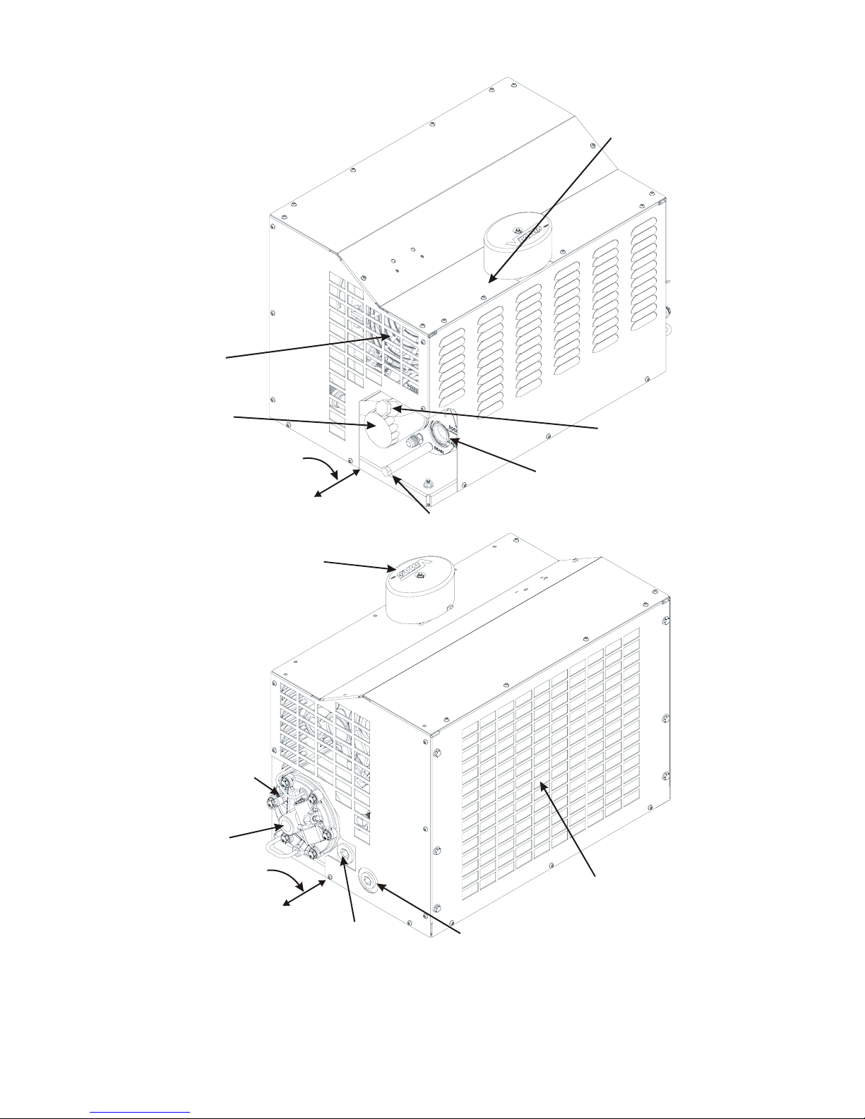
Compressor air filter
(must have proper ventilation)
Oil cooler (inside cover,
must have proper ventilation
)
Air discharge port
with check valve
Hydraulic fluid inlet
Hydraulic fluid return
Blowdown cap with
internal coalescing filter
Minimum clearance
for servicing - 6 inches
Compressor oil fill
(shipped full from
the factory)
Oil level sight glass
(make sure this can be easily
accessed for daily inspection)
Compressor oil drain
Oil filter
Cooling fan
Regulator on
inlet valve
(inside cover)
Minimum clearance
for servicing - 6 inches
Figure 1 – System components
VMAC – Vehicle Mounted Air Compressors
Toll Free: 1-800-738-8622 Local: 1-250-740-3200
Fax: 1-250-740-3201
5
Figure 2 – System wiring

VMAC – Vehicle Mounted Air Compressors
Toll Free: 1-800-738-8622 Local: 1-250-740-3200
Fax: 1-250-740-3201
6
2.0 Installation Requirements
The information in this section is very important for
proper operation of the compressor. Read these
requirements before beginning installation.
Before installing the compressor, examine the possible locations and
consider the following factors when selecting a location:
• it is convenient for making electrical, hydraulic and air
connections and does not require extensive plumbing
• hose and wire lengths will be the shortest possible and a
minimum number of 90 degree fittings will be used
• the oil level at the sight glass can be checked easily
• there will be sufficient clearance around the unit for good air
circulation and effective cooling
• it can be serviced easily without having to disconnect lines or
remove and reposition the unit
• it will be protected from excessive exposure to the elements
and possible incidental damage from other operations
• it is away from heat sources such as engines, exhaust
systems or other components that generate heat
• it is not in a location where it will be exposed to high
contamination levels, including combustible gases
2.1 Ventilation Requirements
During operation, the PREDATAIR60 can develop
considerable heat, as much as a house furnace.
Proper ventilation is vital for proper operation and to
avoid damage to components.
If you are installing the compressor into a new
configuration, refer to section 5.0 Testing Ventilation for
information.
2.1.1 Top Mounting
This is the preferred mounting location. Placing the unit on top of
the service body (Figure 3) provides the best access to ambient
air and provides the best cooling. Maintain a minimum of 6”
between the sides of the compressor housing and all other solid
objects
!

VMAC – Vehicle Mounted Air Compressors
Toll Free: 1-800-738-8622 Local: 1-250-740-3200
Fax: 1-250-740-3201
7
2.1.2 Enclosed Mounting
Mounting the PREDATAIR60 in an enclosure (Figure 3) will limit
the access to ambient air, restrict the escape of hot air from
around the unit and have an adverse effect on cooling. Make sure
that adequate ventilation is provided so the cooling system will
function properly.
Top mount
Enclosed mount
Figure 3 – Mounting locations
It is not possible to make absolute recommendations regarding
ventilation because of the widely differing circumstances that are
possible. Duty cycle, ambient temperature and enclosure shape
are some of the important variables.
Significant ventilation and additional cooling will be
required if the PREDATAIR60 is mounted in the
same enclosure as the hydraulic oil reservoir. The
heat generated during operation will continue to
heat the hydraulic oil, even with fresh, ambient air
entering the cooler
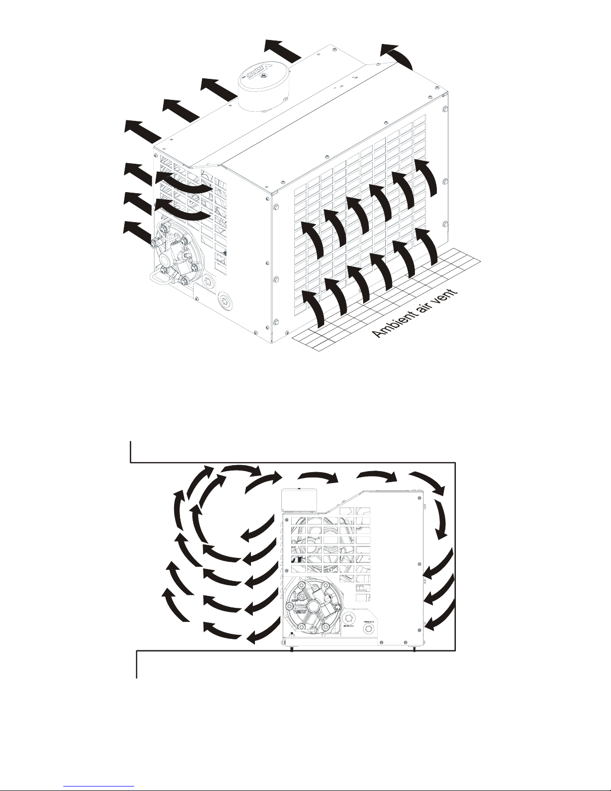
Ideal ventilation will provide good airflow through the unit with no
restrictions (Figure 4). Cool ambient air ducted to the cooler and
exhaust fan are recommended.
!
VMAC – Vehicle Mounted Air Compressors
Toll Free: 1-800-738-8622 Local: 1-250-740-3200
Fax: 1-250-740-3201
8
Figure 4 – Ideal ventilation with ambient air vent of a suitable
size for the application
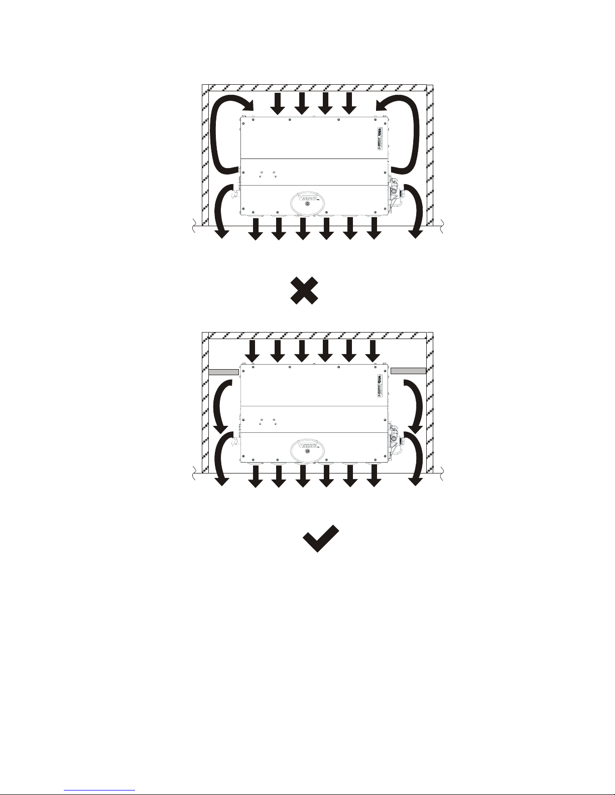
Avoid installing deep into enclosures that will not permit adequate air
circulation (Figure 5).
Enclosure
Enclosure
Figure 5 – Avoid deep installation
VMAC – Vehicle Mounted Air Compressors
Toll Free: 1-800-738-8622 Local: 1-250-740-3200
Fax: 1-250-740-3201
9
The effects of hot air recirculation drastically reduce cooling but
those effects can be reduced by using air dams (Figure 6).
Top view
Hot air recirculating
Top v ie w
Dams installed to block recirculation
Figure 6 – Reducing hot air recirculation
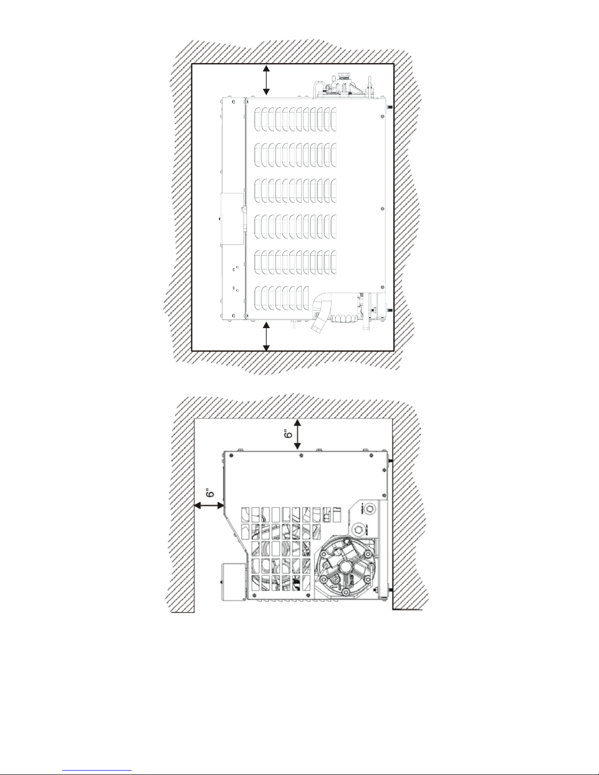
Recommended minimum clearances if no back ventilation is possible
are very important (Figure 7) but are not adequate for 100%
operational capacity (see section 5.0 Testing Ventilation).
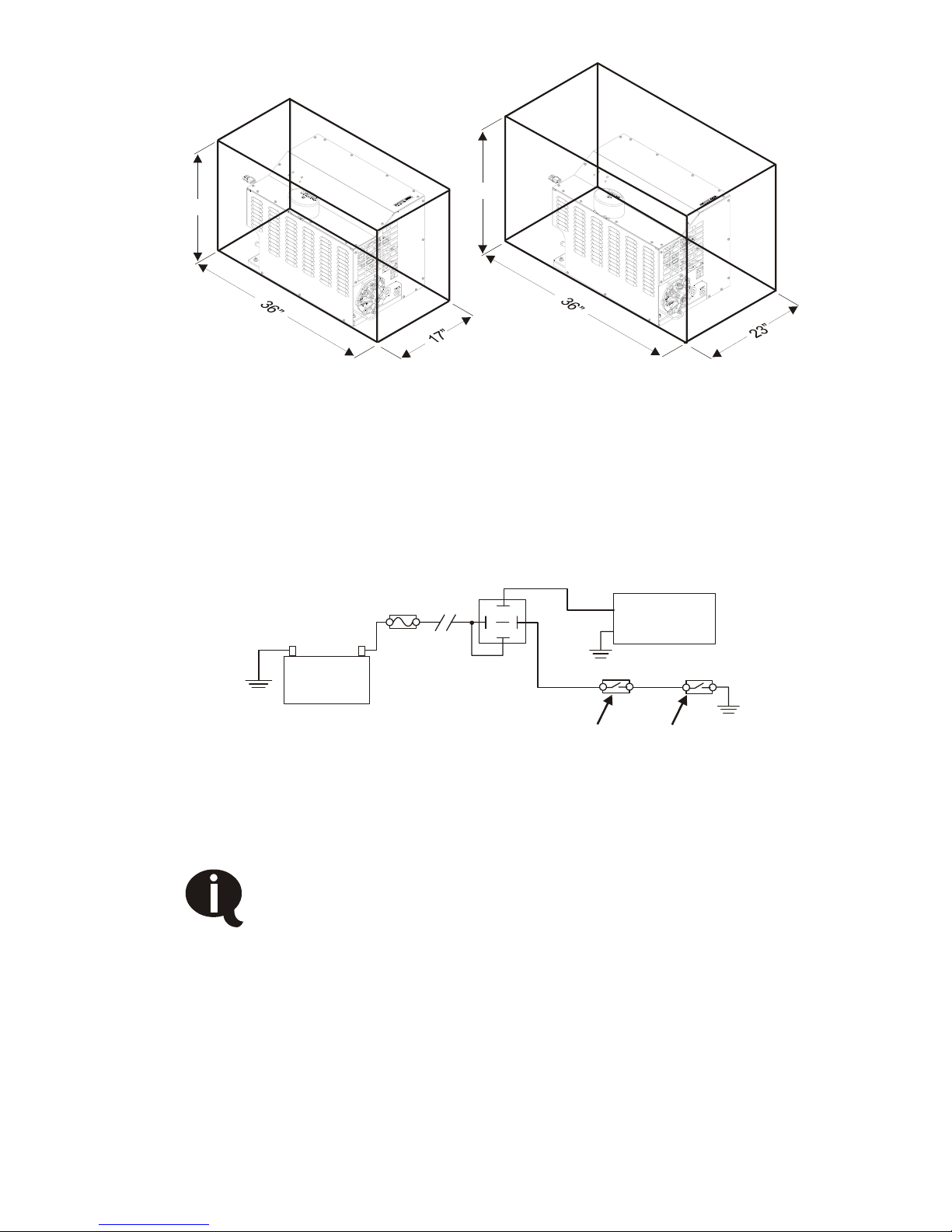
Enclosure sizes (Figure 8) should meet minimum requirements for
optimum operation (see section 5.0 Testing Ventilation).
VMAC – Vehicle Mounted Air Compressors
Toll Free: 1-800-738-8622 Local: 1-250-740-3200
Fax: 1-250-740-3201
10
6”
6”
6”
6”
Figure 7 – Minimum clearances
VMAC – Vehicle Mounted Air Compressors
Toll Free: 1-800-738-8622 Local: 1-250-740-3200
Fax: 1-250-740-3201
11
22”
24”
With back ventilation Without back ventilation
Figure 8 – Recommended enclosure size
If the PREDATAIR60 is mounted inside a service body with a door
that needs to be manually opened to provide ventilation, install a
switch on the door so that the compressor will only operate when the
door is open (Figure 9).
Battery
Relay
PREDATAIR60
R
emote s
witch
Door switch
Figure 9 – Door switch
2.2 Hydraulic Requirements
If the compressor is being installed on a truck that does
not have a hydraulic system, you will find information
on selecting and installing hydraulic components in
section 6.0 Hydraulic System Data.
Compressor capacity depends on hydraulic flow. For single speed
operation a minimum of 14 GPM and a maximum of 20 GPM
hydraulic oil flow is required. For two speed operation, a minimum of
12 GPM and a maximum of 22 GPM hydraulic oil flow is required.

VMAC – Vehicle Mounted Air Compressors
Toll Free: 1-800-738-8622 Local: 1-250-740-3200
Fax: 1-250-740-3201
12
Nominal Air Flow vs Hydraulic Flow
0
10
20
30
40
50
60
70
12 13 14 15 16 17 18 19 20 21 22
Hydraulic Flow (GPM
)
A
i
r
F
l
o
w
(
C
F
M
)
These are nominal values only. Due to variations in hydraulic system
efficiency, load and flow tests should be performed to confirm that
the desired CFM has been achieved.
If the compressor is being installed on a truck that already has a
functioning hydraulic system, check the specifications for that system
to ensure that it meets minimum requirements.
The information in this manual is based on a fixed displacement
pump. Special considerations may be required for a variable
displacement pump.
2.3 Electrical Requirements
The PREDATAIR60 requires a steady 17 Amps @ 12 VDC to
operate. A 30 Amp fuse or circuit breaker is recommended.
To assure an un-interrupted supply of power, the ground wire should
be routed either to the negative terminal of the battery or to a
substantial, fully grounded point on the vehicle chassis, located in an
area which will provide a good ground at all times.
Power should be tapped directly from the positive terminal of the
battery through a relay with a contact rating of at least 20 Amps.
Using a relay allows the heavy gauge power wire to be routed
directly and permits the use of a light (18 AWG) wire between the
relay and the control switch.

VMAC – Vehicle Mounted Air Compressors
Toll Free: 1-800-738-8622 Local: 1-250-740-3200
Fax: 1-250-740-3201
13
2.3.1 Wire Size Selection
Selecting the correct wire size is vital for proper operation. If the wire
size is too small, voltage drop will be excessive and the compressor
will operate erratically. Measure the length required for both the
power wire and the ground wire, add them together and select the
correct wire size from Table 1.
Total length of Power wire PLUS Ground wire Recommended Wire Gauge
Less than 10 ft. 12AWG
10 ft. to 15 ft. 10AWG
More than 15 ft. 8AWG
Table 1 – Wire gauge size
Never connect the PREDATAIR60 so that it switches on
at the same time as the PTO is engaged. This can cause
sudden, excessive hydraulic pressure which can
damage components.
2.4 Air Receiver Requirements
The PREDATAIR60 uses an unloader system which minimizes fuel
burn, equipment wear, cooling load, enclosure temperature,
hydraulic temperature and noise, when compressed air is not being
used. For this unloader system to work most efficiently, and to avoid
having the compressor loading and unloading too frequently, some
air receiver volume is very beneficial.
If the plumbing downstream from the PREDATAIR60 is tight, a 5
gallon air receiver is adequate. If a receiver tank is not possible,
then consider using the existing welded tubular structure within the
service body as an air receiver. For reference, 21’ of 3/16” wall 2-1/2”
x 2-1/2” square tube has a volume of 5 gallons.
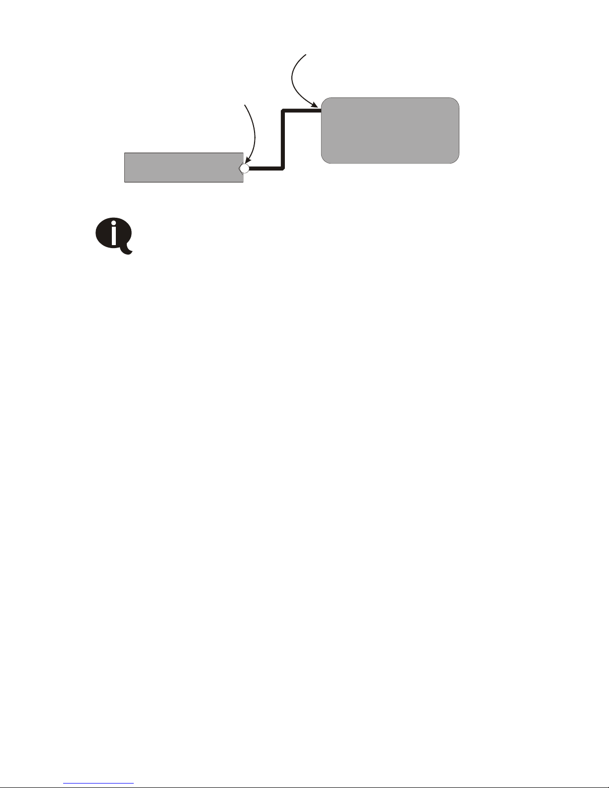
If you use an auxiliary air tank with this system, the line to the
auxiliary tank must be installed as high as possible (not in the bottom
of the tank) to prevent water from clogging the line (Figure 10).
Failure to observe these requirements will result in damage to the
system.
!
VMAC – Vehicle Mounted Air Compressors
Toll Free: 1-800-738-8622 Local: 1-250-740-3200
Fax: 1-250-740-3201
14
PREDATAIR60 Tank
Auxiliary Tank
One-way check valve
built into PREDATAIR60
tank
Install this line high on the
tank, not at the bottom
Figure 10 – Auxiliary tank connection
A one-way check valve is built into the PREDATAIR60
tank. Do not install an additional check valve as this
may cause undesirable operations.
 Loading...