

Page 1
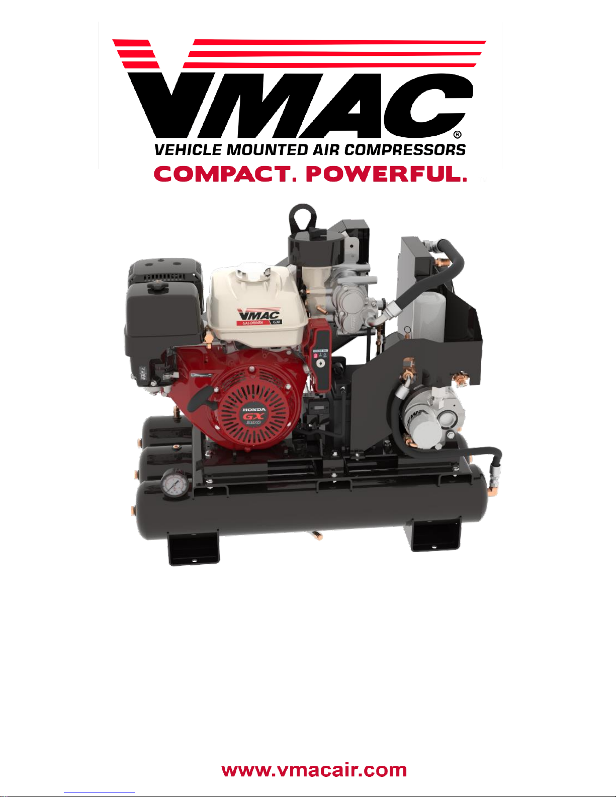
Gas Engine Driven 30 CFM
Air Compressor
Installation, Owner’s and
Service Manual
G300003
Page 2

Page 3

VMAC – Vehicle Mounted Air Compressors
VMAC Technical Support: 1-888-241-2289
VMAC Knowledge Base: www.kb.vmacair.com
1
Gas Engine Driven 30 CFM Air
Compressor
Installation, Owner’s and Service
Manual G300003
Safety .......................................................................................................3
Warranty ..................................................................................................4
Safety Precautions ..................................................................................5
General Information ................................................................................9
Safety Features .......................................................................................10
Operating Principles ...............................................................................11
Extreme Climates and Elevation ............................................................13
System Overview ....................................................................................15
System Controls and Features ..............................................................18
Installation Requirements ......................................................................19
Ventilation Requirements .......................................................................20
Mounting Locations ................................................................................21
Mounting the Compressor .....................................................................22
Before Starting the Gas Engine Driven 30 CFM Air Compressor .......24
Starting and Stopping the Engine .........................................................25
Recommended Accessories ..................................................................30
Air Receiver Tank ....................................................................................31
Setup, Performance Testing and Adjustments ....................................32
Engine rpm Adjustment..........................................................................33
Accessory Products from VMAC ...........................................................34
General Maintenance Information .........................................................37
Maintenance and Repair Safety .............................................................38
Maintenance Schedule ...........................................................................41
Regular Inspection Instructions ............................................................42
200 Hour / 6 Month Service ....................................................................48
400 Hour / 1 Year Service .......................................................................51
Engine Maintenance and Warranty Information ...................................54
Diagnostics and Trouble Shooting ........................................................55
Compressor Regulation and Throttle Actuator Testing ......................61
System Adjustment for Large Receiver Tanks .....................................68
Electrical Components and Testing ................................ ......................69
Component Repair / Replacement .........................................................72
Illustrated Parts List ...............................................................................82
Warranty Registration ............................................................................89
Service Records ......................................................................................91
Page 4
VMAC – Vehicle Mounted Air Compressors
VMAC Technical Support: 1-888-241-2289
VMAC Knowledge Base: www.kb.vmacair.com
2
Document: 1930321
Changes and Revisions
Additional Application Information
• VMAC recommends installing A500044 – Cold Climate Kit if this unit will
be used in temperatures below 0 °C (32 °F).
• Refer to the Honda GX390 Owner’s Manual (VMAC P/N: 1901066) for
engine specific information.
Registered Trademarks
All trademarks mentioned in this manual are the property of their respective
owners. VMAC’s use of manufacturers’ trademarks in this manual is for
identification of the products only and does not imply any affiliation to, or
endorsement of said companies.
Loctite®, Loctite® 242 and Loctite® 567 are registered trademarks of Henkel
AG & Company KGaA.
Honda® is a registered trademark of Honda Motor Co., Ltd.
Important Information
The information in this manual is intended for certified VMAC installers who
have been trained in installation procedures and/or for people with
mechanical trade certification who have the tools and equipment to properly
and safely perform the installation. Do not attempt this installation without the
appropriate mechanical training, knowledge and experience.
Follow all safety precautions for mechanical work. Any fabrication for correct
fit in modified vehicles must follow industry standard “best practices”.
Notice
Copyright © 2017 VMAC Global Technology Inc. All Rights Reserved. These
materials are provided by VMAC for informational purposes only, without
representation or warranty of any kind, and VMAC shall not be liable for
errors or omissions with respect to the materials. The only warranties for
VMAC products and services are those set forth in the express warranty
statements accompanying such products and services, if any, and nothing
herein shall be construed as constituting an additional warranty. Printing or
copying of any page in this document in whole or in part is only permitted for
personal use. All other use, copying or reproduction in both print and
electronic form of any part of this document without the written consent of
VMAC is prohibited. The information contained herein may be changed
without prior notice.
Printed in Canada
Revision
Revision Details
Revised
by
Checked by
Implemented
Eng.
Tech.
Qual.
Mech.
Elec.
A
Initial Release
MSP
MRH
N/A
GB
AMG
21 Aug 2017
B
ECN 17-140: Fan relay update
NAC
MRH
N/A
MSP
AWG
7 Sept 2017
KEEP THIS MANUAL WITH THE GAS ENGINE
DRIVEN 30 CFM COMPRESSOR UNIT FOR
USER REFERENCE
Page 5
VMAC – Vehicle Mounted Air Compressors
VMAC Technical Support: 1-888-241-2289
VMAC Knowledge Base: www.kb.vmacair.com
3
Safety
Important Safety Notice
The information contained in this manual is based on sound engineering
principles, research, extensive field experience and technical information.
Information is constantly changing with the addition of new models,
assemblies, service techniques and running OEM changes. If a discrepancy
is found in this manual, contact VMAC prior to initiating or proceeding with
installation, service or repair. Current information may clarify the issue. Any
person with knowledge of such discrepancies, who proceeds to perform
service and repair assumes all risks.
Only proven service procedures are recommended. Anyone who departs from
the specific instructions provided in this manual must first assure that their
safety and that of others is not being compromised and that there will be no
adverse effects on the operational safety or performance of the equipment.
VMAC will not be held responsible for any liability, consequential damages,
injuries, loss or damage to individuals or to equipment as a result of the
failure of any person to properly adhere to the procedures set out in this
manual or standard safety practices. Safety should be the first consideration
when performing any service operations. If there are any questions
concerning the procedures in this manual or more information is required,
please contact VMAC before beginning repairs.
Safety Messages
This manual contains various warnings, cautions and notices that must be
observed to reduce the risk of personal injury during installation, service or
repair and the possibility that improper installation, service or repair may
damage the equipment or render it unsafe.
This symbol is used to call attention to instructions concerning
personal safety. Watch for this symbol; it points out important safety
precautions, it means, “Attention, become alert! Your personal
safety is involved”. Read the message that follows and be aware of
the possibility of personal injury or death. As it is impossible to warn
of every conceivable hazard, common sense and industry standard
safety practices must be observed.
This symbol is used to call attention to instructions on a specific
procedure that if not followed may damage or reduce the useful life
of the compressor or other equipment.
This symbol is used to call attention to additional instructions or
special emphasis on a specific procedure.
Page 6
VMAC – Vehicle Mounted Air Compressors
VMAC Technical Support: 1-888-241-2289
VMAC Knowledge Base: www.kb.vmacair.com
4
Warranty
VMAC Standard Warranty (Limited)
For complete warranty information, including both VMAC
Standard Warranty (Limited) and VMAC Lifetime Warranty
(Limited) requirements, please refer to our current
published warranty located at:
www.vmacair.com/warranty
If you do not have access to a computer, please contact us and we will be
happy to send you our warranty.
VMAC’s warranty is subject to change without notice.
VMAC Lifetime Warranty (Limited)
A VMAC Lifetime Limited Warranty is
offered on the base air compressor
only and only on UNDERHOOD,
Hydraulic Driven, Transmission
Mounted, Gas and Diesel Engine
Driven Air Compressors,
Multifunction Power Systems, and
other products as defined by VMAC,
provided that (i) the purchaser fully
completes and submits a warranty registration form within 3 months of
purchase, or 200 hours of operation, whichever occurs first; (ii) services are
completed in accordance with the Owner’s Manual; (iii) proof of purchase of
applicable service kits are made available to VMAC upon request.
The VMAC Lifetime Warranty is applicable to new products shipped on or
after 1 October, 2015.
Warranty Registration
The VMAC warranty registration form is located near the back of this manual.
This warranty registration form must be completed and sent to VMAC at the
time of installation for any subsequent warranty claim to be considered valid.
There are 4 ways the warranty can be registered with VMAC:
Online
www.vmacair.com/warranty
Email
Fax
(250) 740-3201
Mail
VMAC - Vehicle Mounted Air Compressors
1333 Kipp Road, Nanaimo, BC, Canada V9X 1R3
Page 7
VMAC – Vehicle Mounted Air Compressors
VMAC Technical Support: 1-888-241-2289
VMAC Knowledge Base: www.kb.vmacair.com
5
Safety Precautions
As it is impossible to warn of every possible hazard that may
result from operating or servicing this system, common sense
and industry standard safety practices must be observed.
Read this information before operating the compressor for the first time.
Follow the information and procedures in this manual for operation,
maintenance and repair. Observe the following items to reduce the chance of
personal injury or equipment damage.
Follow all safety precautions for mechanical work. Moving belts and rotating
components are an extreme hazard. Stay clear of all moving parts when the
system is operating. Only qualified personnel should perform maintenance
and repair on system components and only while the system is properly shut
down.
Proper service and repair are important to the safety of the service technician
and the safe, reliable operation of the equipment. Always use genuine VMAC
and/or Honda replacement parts.
The procedures described in this service manual are effective methods of
service and repair. Some procedures may require the use of tools specially
designed for a specific purpose. Anyone using a replacement part, service
procedure or tool must first determine that neither their safety nor the safe
operation of the equipment will be compromised by the replacement part,
service procedure or tool selected.
Warning
Breathing gasoline vapours or engine exhaust can expose
you to chemicals known to the State of California to cause
cancer and birth defects or other reproductive harm.
• Always start and operate the engine in a well
ventilated area.
• If in an enclosed area, vent the exhaust to the outside.
• Do not modify or tamper with the exhaust system.
Burn Hazard
• The engine, exhaust and the compressor system get
very hot during operation, contact with the components
or the oil can cause serious injury. Allow sufficient time
for the system to cool before performing service.
• Never allow any part of your body to contact the
engine or compressor components.
Page 8

VMAC – Vehicle Mounted Air Compressors
VMAC Technical Support: 1-888-241-2289
VMAC Knowledge Base: www.kb.vmacair.com
6
Personal Safety
• Do not breathe the compressor air. Vaporized oil is a
respiratory hazard.
• Do not breathe engine exhaust, gasoline engines
produce carbon monoxide, a poisonous odorless gas
which can cause death. Do not start or operate this
compressor in an enclosed area.
• Always use the appropriate personal protective
equipment, particularly eye and hearing protection
when operating air powered equipment.
Fire and Explosion Hazard
• Vaporized oil propelled by high pressure air is an
explosive mixture.
• Fire in the compressor can cause an explosion and
flame projection. Should this occur, there is potential
for serious injury or death.
• Operate the compressor in a well ventilated area free
of flammable vapors, dust, or other combustible
materials.
• Do not refuel the engine while the system is running or
hot.
• Do not refuel the engine in an enclosed space or area
with poor ventilation.
• If fuel is spilled, clean the area and wait for it to dry
before starting the engine.
• Never place objects against or on top of the
compressor.
• Never expose the WHASP Tank or compressor to
extreme heat.
Lead Acid Battery Hazard
Working near lead/acid batteries is dangerous. Batteries
may generate sulphuric acid and explosive gasses during
regular operation. Lead/acid batteries may explode if
exposed to a spark.
• Follow all safety precautions when jump starting or
charging a battery.
• Never attempt to jump start a frozen battery.
• Never overcharge a battery.
Page 9
VMAC – Vehicle Mounted Air Compressors
VMAC Technical Support: 1-888-241-2289
VMAC Knowledge Base: www.kb.vmacair.com
7
Compressor Air and Oil Hazard
• The compressor system is under sufficient pressure
that a leak could force the air/oil mixture through the
skin directly into your bloodstream. This could cause
serious injury or death.
• Ensure the system is completely depressurized before
attempting maintenance or repair.
• Do not use compressed air to clean off clothing or skin,
compressed air can penetrate the skin causing serious
injury or death.
• Do not move or service the compressor while it is
pressurized or operating.
• Do not move the compressor by pulling on any hoses.
• Components and hoses under pressure could separate
suddenly, fly out and cause serious injury or death. If
equipped, the air receiver tank must be drained before
servicing any components in the compressor system.
• Never adjust or attempt to make any repairs to the
system while the engine is running. Components and
hoses under pressure could fail and cause serious
injury or death.
Burst Hazard
• Serious injury or death may result from an air tank
explosion.
• Never exceed manufacturer’s maximum air pressure
rating.
• Do not repair components, only replace with approved
parts.
• Do not tamper with or disable factory safety
equipment.
Moving Parts Hazard
• Before performing service, disconnect the negative
battery cable and the spark plug wire to prevent
unexpected engine start.
• Do not operate the compressor without guards in
place. If the guards are damaged or missing, replace
them before operating the equipment.
Page 10
VMAC – Vehicle Mounted Air Compressors
VMAC Technical Support: 1-888-241-2289
VMAC Knowledge Base: www.kb.vmacair.com
8
General Warnings
• Disconnect the spark plug wire before attempting any
repair or service.
• Be attentive for unexplained changes in operation
parameters and record any changes.
• Check the compressor oil level and condition before
starting the system. Do not add or change oil while the
system is running. Use only approved oil.
• The compressor operates anytime the engine is
running. Avoid contact with the compressor, hoses, or
engine during operation.
• Keep hoses and wiring away from hot, sharp, or
moving components.
• Use only approved hoses and replacement parts.
• Do not modify the equipment.
• Do not operate the air compressor when fatigued or
under the influence of alcohol or drugs.
• Know how to operate the compressor, fully read the
manual.
• Check equipment before every use.
• Never bypass or disable any of the safety equipment.
• Never adjust or attempt to make any repairs to the
compressor system while the engine is running.
Components and hoses under pressure could fail and
cause serious injury or death.
Page 11
VMAC – Vehicle Mounted Air Compressors
VMAC Technical Support: 1-888-241-2289
VMAC Knowledge Base: www.kb.vmacair.com
9
General Information
Before Starting
Read this manual as well as the Honda Owner’s Manual prior to installing or
operating the Gas Engine Driven 30 CFM Air Compressor to ensure
familiarity with the components, installation requirements and how to operate
the unit.
Open the package, unpack the components and identify them using the
included IPL on page 82.
Hose Information
The hoses used in VMAC compressor systems have a specific inner liner that
is compatible with VMAC compressor oil. Use of hoses other than those
supplied or recommended by VMAC may cause compressor damage and
may void your warranty. Please contact VMAC for replacement hoses and
further information.
Ordering Parts
To order parts, contact a VMAC dealer. The dealer will ask for the VMAC
serial number, part number, description and quantity. Locate the nearest
dealer online at www.vmacair.com/dealer-locator or call 1-877-912-6605.
Page 12
VMAC – Vehicle Mounted Air Compressors
VMAC Technical Support: 1-888-241-2289
VMAC Knowledge Base: www.kb.vmacair.com
10
Safety Features
Do not disable or bypass any safety components. Disabling
or bypassing safety components could result in equipment
damage, injury or death.
Read this manual in its entirety prior to operating or
performing any service or repairs to the Gas Engine Driven
30 CFM Air Compressor.
Gas Engine Driven 30 CFM Air Compressor
Safety Components
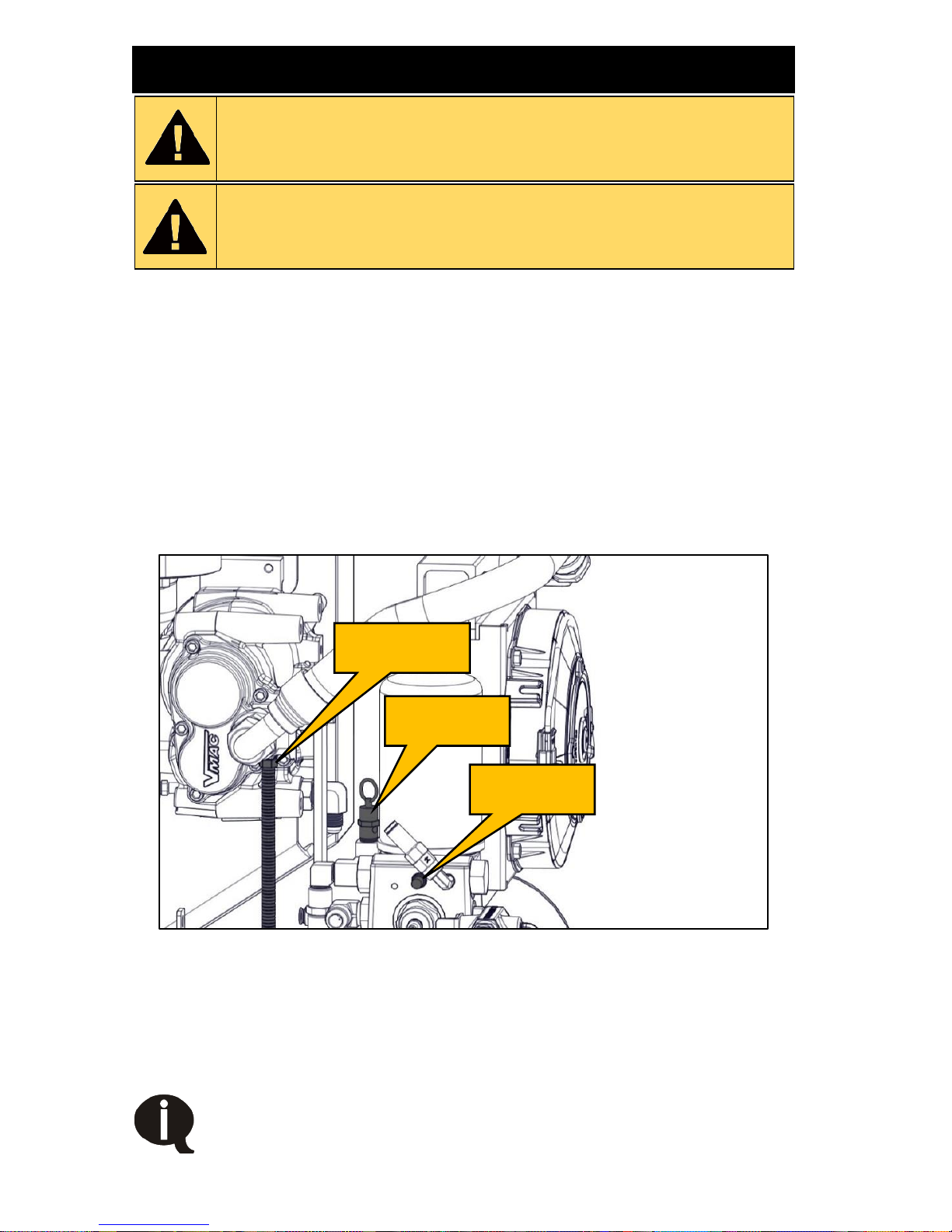
• 200 psi pressure relief valve in the separation manifold.
• Blowdown muffler to discharge system pressure on shut down.
• Temperature safety switch in compressor.
• 15 A fuse protects the OEM electrical system (located inside the
OEM key start enclosure).
• 15 A fuse protects the fan’s electrical system (located in the wiring
harness next to the battery).
Figure 1 – Safety components (Shroud removed for clarity)
Automatic Overheat Shut down
If the compressor oil temperature exceeds 140 °C (284 °F), the thermostatic
switch will disable the engine. The cooling fan is powered by the battery and
will continue to run as needed to cool the compressor.
The engine will not be able to be restarted until the system has
cooled and the temperature switch has closed.
Temperature
switch
200 psi relief
valve
Blowdown
muffler
Page 13

VMAC – Vehicle Mounted Air Compressors
VMAC Technical Support: 1-888-241-2289
VMAC Knowledge Base: www.kb.vmacair.com
11
Operating Principles
Air Compression
The Gas Engine Driven 30 CFM Air Compressor uses a VMAC designed and
manufactured flooded lobe, rotary screw compressor. The oil filled
compressor housing contains 2 rotors. Compression occurs when air (at
normal atmospheric pressure) enters a chamber where it is trapped between
meshing rotor lobes. Cooled oil is injected into the rotors during compression
to lubricate the rotors and bearings, absorb the heat of compression, and seal
the rotor lobes to allow for efficient compression. As the rotors rotate, the
meshing lobes compress the volume of the trapped air/oil mixture before
sending it down the discharge line to be cooled and separated by the Waste
Heat Air Separation Package (WHASP) Tank.
Oil Separation and Cooling
The WHASP Tank is a 2 stage air/oil separator and oil cooler. The hot air/oil
mixture from the compressor enters the cooler at the top of the WHASP Tank
where the mixture is cooled and the majority of the oil separates from the air
and settles into the reservoir tank below the cooler (first stage separation).
The cooled oil then passes through a high pressure oil filter before being
returned to the compressor via the oil return line. The air stream then passes
through a coalescing filter where the remaining oil is removed (second stage
separation). The oil collected by the coalescing filter is returned to the
compressor via the 1/4 in PTFE scavenge tube.
A liquid to air cooler with electric fan maintains the operating temperature
which reduces the temperature of the compressed air and increases the
system’s durability.
Minimum Pressure Check Valve
The WHASP Tank has a built-in minimum pressure check valve (MPCV) to
maintain a minimum pressure of approximately 60 psi (414 kPa) in the
WHASP Tank, this ensures there is adequate compressor lubrication, cooling,
and oil separation in the coalescing filter. Air will not flow out of the WHASP
Tank until approximately 60 psi is reached. The MPCV is factory set and
requires no adjustment or servicing.
The VMAC WHASP Tank has a built-in check valve. Use of
an additional check valve is not required and may cause
erratic performance.
Page 14

VMAC – Vehicle Mounted Air Compressors
VMAC Technical Support: 1-888-241-2289
VMAC Knowledge Base: www.kb.vmacair.com
12
Filtration
VMAC rotary screw compressors are designed and machined to exacting
tolerances. Foreign particles entering the compressor can damage system
components such as seals, bearings, rotors, as well as the inside of the
housing, resulting in performance losses and reduced system life.
The system is equipped with a replaceable paper element inlet air filter, spin
on high pressure oil filter and a spin on coalescing filter.
These system filters enhance performance and extend component life by
reducing damage from dust and other debris. Proper maintenance is required
to maintain system performance and extend the system’s life.
Compressor Drive, Belt and Tensioning
The compressor is directly driven by a 4 rib belt. Anytime the engine is
running the compressor is running. The system has an automatic belt
tensioner, manual adjustment is not required.
Pressure Regulation
Pressure regulation is achieved with a combination of an inlet valve regulator,
a mechanical unloader valve and a discharge valve. Use a Filter Regulator
Lubricator (FRL) to regulate downstream pressure to the tools.
System Pressure Unload
Internal system pressure is controlled via a mechanical unloader valve. When
downstream air pressure reaches 150psi (air pressure to the air tools), the
mechanical unloader valve activates and sends a signal to the mechanical
discharge valve to open. When open, the mechanical discharge valve sends
internal system pressure (pressure inside the compressor and WHASP Tank)
to the inlet valve and closes the compressor air intake poppet. Internal air
pressure is then vented to a nominal value which reduces the load on the
engine. This allows the control system to reduce engine speed which
improves fuel efficiency, as well as reducing emissions and wear and tear on
the system. When downstream pressure drops below 120 psi, the unloader
valve will close and “load” the system, allowing it to build air.
Engine Speed Control
The engine speed is controlled mechanically by a pneumatic throttle which
raises and lowers engine rpm according to air demand. Operator input is not
required on the throttle lever.
Spark Arrester
The gas engine is supplied with a spark arrester.
For more information regarding the spark arrester, refer to the Honda GX390
Owner’s Manual supplied with the system (VMAC P/N: 1901066).
Page 15

VMAC – Vehicle Mounted Air Compressors
VMAC Technical Support: 1-888-241-2289
VMAC Knowledge Base: www.kb.vmacair.com
13
Extreme Climates and Elevation
The Gas Engine Driven 30 CFM Air Compressor has been
designed to operate in moderate climates of 0 °C to +40 °C
(32 °F to +104 °F) and at elevations below 3,500 feet.
Operating outside of this range may result in performance
issues with the engine and compressor.
Cold Environment Operation
The Gas Engine Driven 30 CFM Air Compressor system is not
designed or recommended for use in cold climates (below 0 °C /
32 °F) unless equipped with a VMAC cold climate kit
(P/N: A500044).
Cold Environment Recommendations
Ensure the following conditions are met before starting the compressor:
• Use the choke in cold environments, or for first start of the engine.
• The system’s components must all be at, or above 0 °C (32 °F). Starting
the system while any of the components are below 0 °C (32 °F) may
result in excessive engine cranking while starting, the engine failing to
start, belt slippage, and engine stalling. Use the optional A500044 Cold
Climate Kit or store the system indoors and start it while the components
are still warm.
• For engine oil recommendations in temperatures below 0 °C (32 °F),
refer to the Honda Owner’s Manual supplied with the system. Failure to
follow the recommendations in the Honda Owner’s Manual may result in
poor engine performance or engine damage.
• The unloader valve should be manually activated to aid start up; this will
reduce the load on the compressor, resulting in less load on the engine
during warm up (Figure 2).
While the unloader valve is manually opened, the compressor
will only produce approximately 40 psi. Once the engine has
reached normal operating temperature, close the unloader
valve to allow the system to build to full system pressure.
The optional A500044 Cold Climate Kit is a starting aid only.
Contact a Honda dealer for recommendations when operating
the engine below -15 °C (5 °F).
Figure 2 – Unloader valve
Unloader valve
with manual
unload actuator
Page 16

VMAC – Vehicle Mounted Air Compressors
VMAC Technical Support: 1-888-241-2289
VMAC Knowledge Base: www.kb.vmacair.com
14
Hot Environment Operation
Operating the Gas Engine Driven 30 CFM Air Compressor fully loaded for
extended periods in temperatures above 40 °C (104 °F) may result in the
system shutting down due to the compressor oil overheating. Placing high
demand on the engine (e.g. continuous demand @ 145 psi) for extended
periods can also result in higher than normal engine oil temperatures. To
avoid overheating the engine or compressor, VMAC recommends installing
an air receiver tank. This will help to reduce the duty cycle of the compressor
by allowing it to unload.
The compressor system is protected by a compressor oil temperature switch
that opens at 140 °C (284 °F) and shuts down and disables the engine until
the compressor oil temperature drops below 139 °C (282 °F). The cooling fan
will continue to operate at anytime as it is powered directly from the battery.
If the Gas Engine Driven 30 CFM Air Compressor shuts off due to overheat,
allow the system to cool sufficiently before restarting.
For engine oil recommendations in temperatures above 40 °C (104 °F) refer
to the Honda GX390 Owner’s Manual supplied with the system (VMAC P/N:
1901066). Failure to follow the information supplied in the Honda Owner’s
Manual may result in poor engine performance or engine damage.
Hot Environment Recommendations:
• Ensure there is an adequate supply of cool ambient air to the unit.
• Ensure the exhaust and hot air are able to vent from the system with no
restrictions.
• Ensure the WHASP radiator fins and engine recoil starter areas are
clear of debris.
• Install an external fan to direct cool air toward the engine and air
compressor.
• Ensure the engine and compressor are serviced at correct intervals.
A receiver tank can help prevent overheating issues by
lowering the duty cycle of the compressor.
High Altitude operation
The Gas Engine Driven 30 CFM Air Compressor has been designed to
operate from 0 to 3,500 feet above sea level.
Operation above 3,500 feet may limit the compressor performance and may
cause the engine to stall. For operation between 3,500 and 5,000 feet,
lowering the compressor duty cycle is recommended.
For more information regarding high altitude operation refer to the Honda
GX390 Owner’s Manual supplied with the system. (VMAC P/N: 1901066).
Failure to follow the Honda Owner’s Manual may result in poor engine
performance or engine damage.
Engines modified for high altitude operation must be returned
to original factory specifications prior to use below 5,000 feet
to prevent serious engine damage.
Page 17
VMAC – Vehicle Mounted Air Compressors
VMAC Technical Support: 1-888-241-2289
VMAC Knowledge Base: www.kb.vmacair.com
15
System Overview
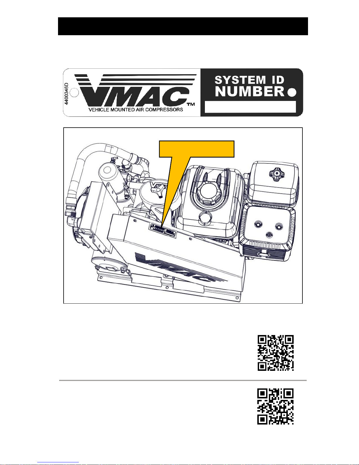
The serial number is located near the top of the belt guard. Have this number
ready when registering the warranty, ordering parts, or when calling in for
technical support (Figure 3).
Figure 3 – Serial number plate and location
Support and Parts
To order parts, contact a local dealer or contact the sales
team.
Dealer locator: http://www.vmacair.com/dealer-locator/
Toll free: 1-(800) 738-8622
Email: [email protected].
For technical support visit VMAC’s Knowledge Base or
contact the technical support team.
Serial number plate
Page 18
VMAC – Vehicle Mounted Air Compressors
VMAC Technical Support: 1-888-241-2289
VMAC Knowledge Base: www.kb.vmacair.com
16
The compressor is driven by a belt; any time that the engine is
running, the compressor is being driven.
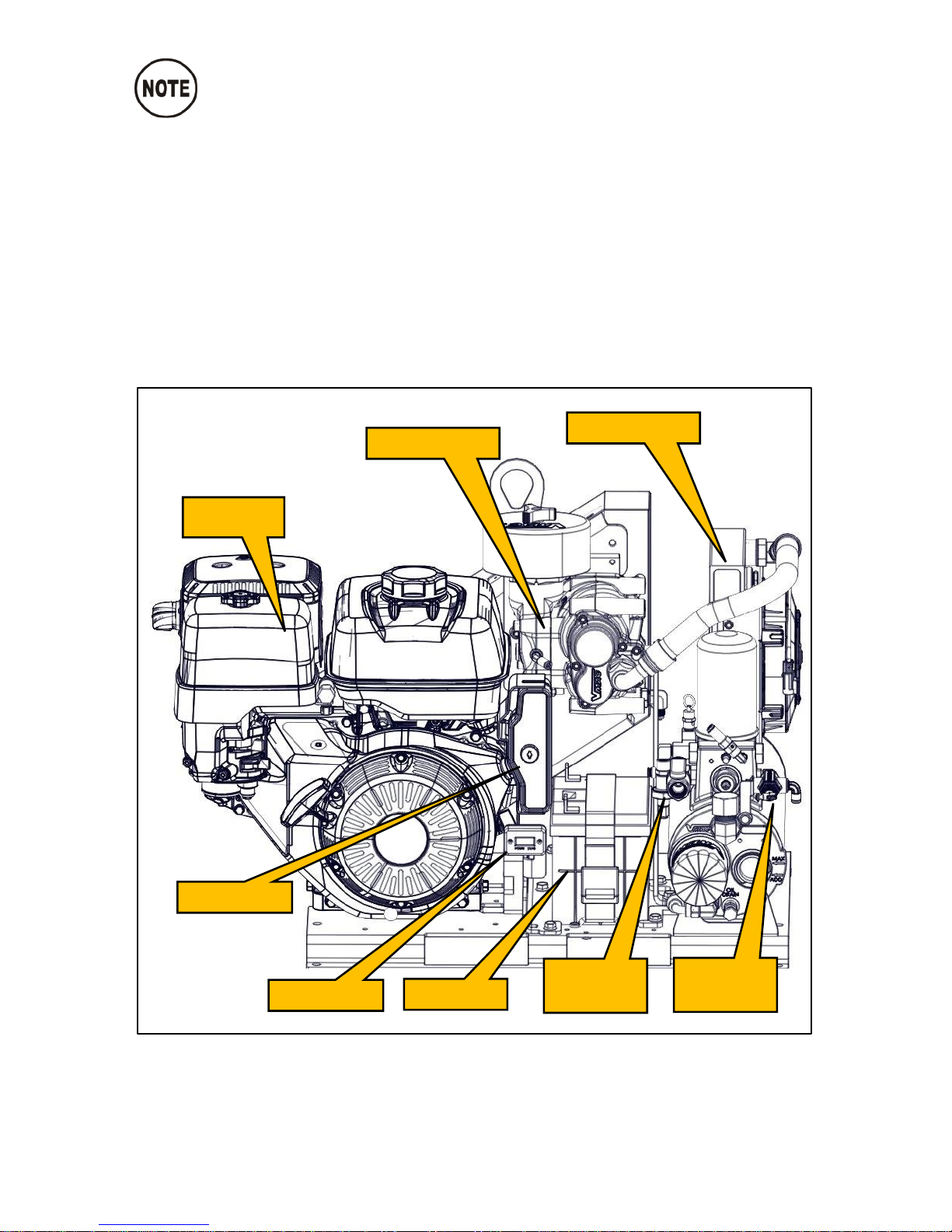
System Components (Front)
• WHASP Tank
• Rotary screw compressor
• Key start
• Hour meter
• 12 V battery
• Honda GX390 gasoline engine
• Unloader valve
• Discharge valve
Figure 4 – System overview (Shroud removed for clarity)
Engine
Compressor
WHASP Tank
Hour meter
Key start
Battery
Unloader
valve
Discharge
valve
Page 19
VMAC – Vehicle Mounted Air Compressors
VMAC Technical Support: 1-888-241-2289
VMAC Knowledge Base: www.kb.vmacair.com
17
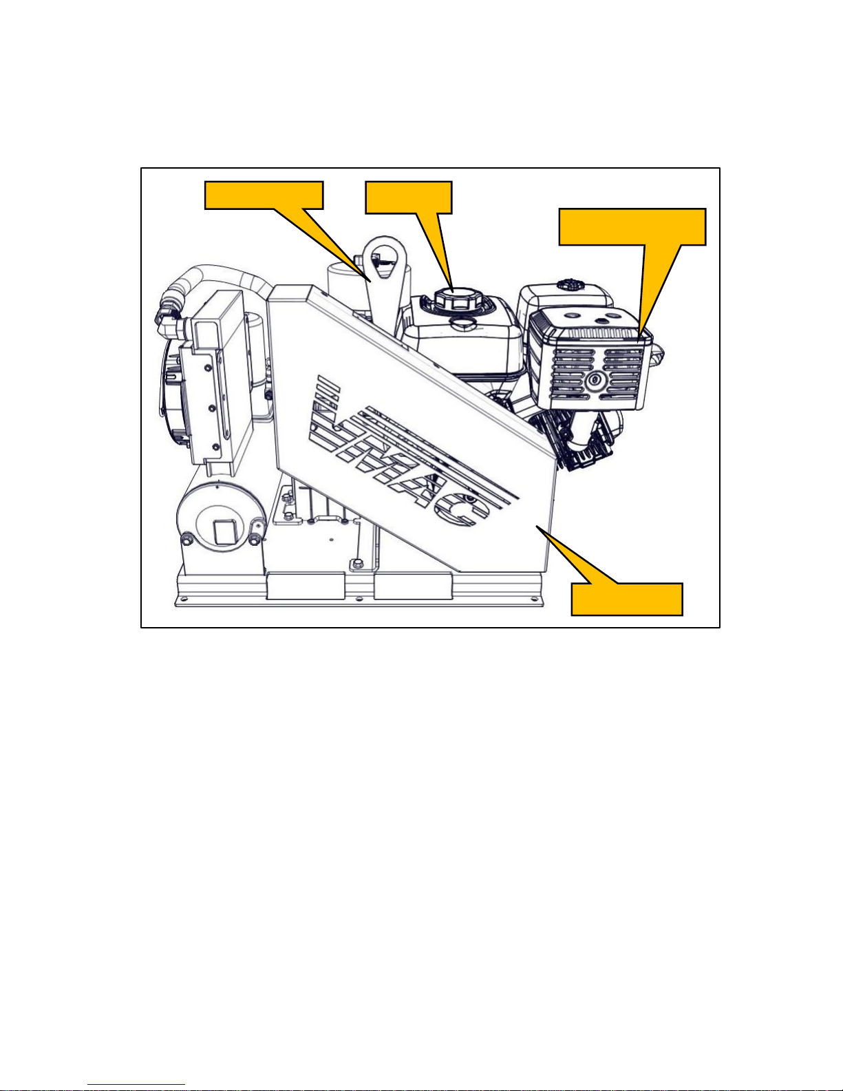
System Components (Back)
• Lifting eye
• Belt shroud
• Fuel fill
• Exhaust shroud
Figure 5 – System overview
Lifting eye
Fuel fill
Belt shroud
Exhaust shroud
Page 20
VMAC – Vehicle Mounted Air Compressors
VMAC Technical Support: 1-888-241-2289
VMAC Knowledge Base: www.kb.vmacair.com
18
System Controls and Features
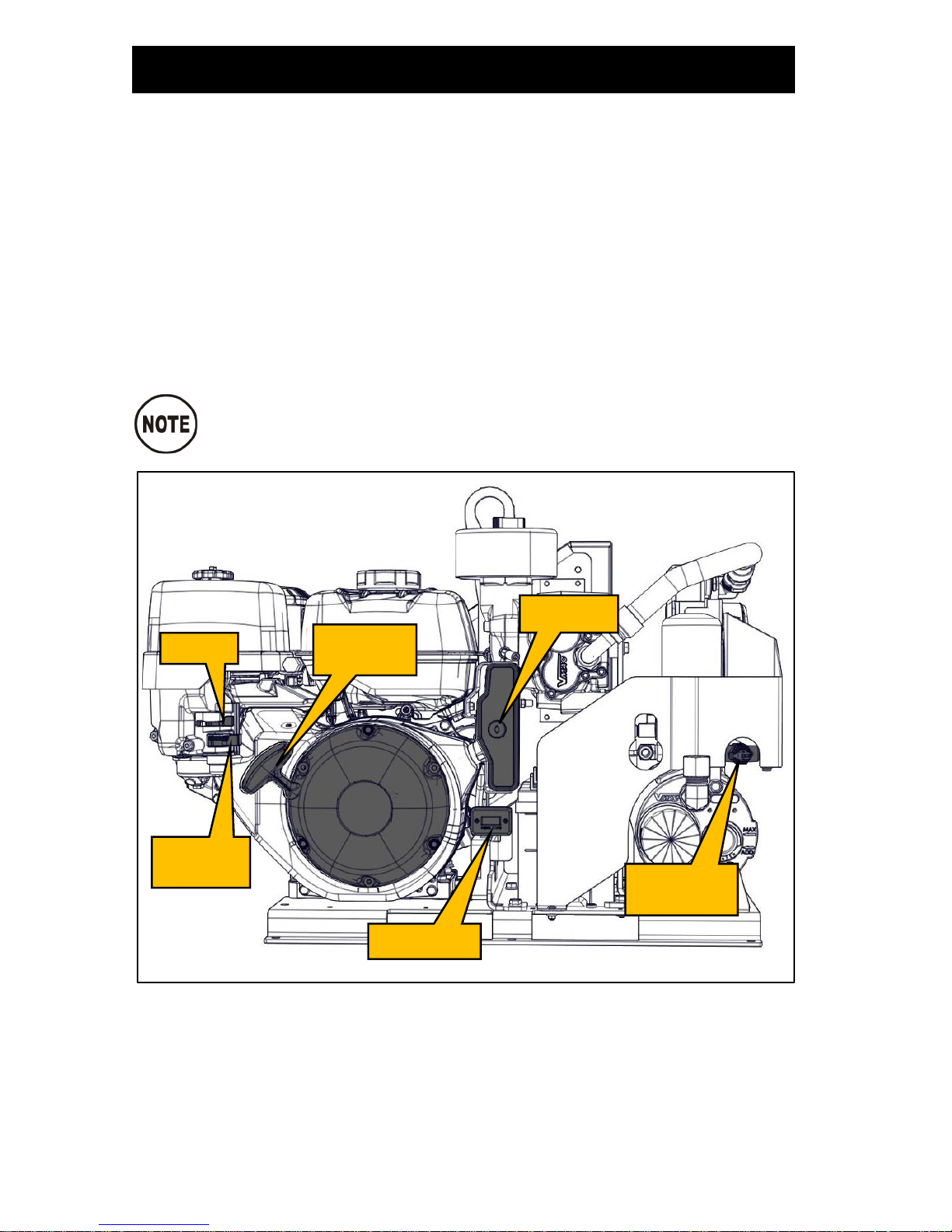
The Gas Engine Driven 30 CFM Air Compressor includes the following
controls and features (Figure 6):
• Electric key start with recoil pull start backup.
• Manual choke.
• Compressor overtemperature switch (shuts down the engine).
• Intelligent throttle which increases or decreases engine rpm based on air
demand (reduces fuel consumption when no air is needed).
• Automatic system pressure unload with manual override (when the
system is “unloaded”, engine speed can be reduced, decreasing engine
noise, emissions and wear and tear, while increasing fuel efficiency).
• Hour meter (runs any time the engine is running).
• Automatic blowdown (depressurizes the system when it is shut down).
The electric fan on the WHASP Tank can turn on at any time.
This is normal operation.
Figure 6 – System controls overview
Choke
Fuel shut
off
Hour meter
Key start
Unloader
valve
Recoil
pull start
Page 21
VMAC – Vehicle Mounted Air Compressors
VMAC Technical Support: 1-888-241-2289
VMAC Knowledge Base: www.kb.vmacair.com
19
Installation Requirements
The information in this section is very important for proper
operation of the compressor. Read these requirements
before beginning installation.
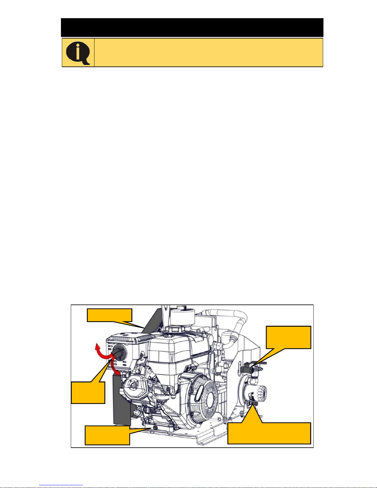
When determining a mounting location for the Gas Engine Driven 30 CFM Air
Compressor, ensure the following conditions are met:
• The fuel shut off valve is easily accessible (the fuel valve must be shut off
when the unit is not in use, including during transport).
• The sight glass, oil drain and filters on the WHASP Tank are easily
accessible for service.
• The belt guard is accessible and can be removed for service.
• The engine oil drain, oil fill, fuel fill, and air filter are easily accessible for
service (the VMAC Remote Oil Drain accessory can help facilitate
servicing the engine and compressor oil P/N: A500043).
• There is adequate access to cool fresh air for optimum engine
performance.
• There is sufficient clearance around the unit for good air circulation and
effective cooling.
• The unit is mounted in a position where hot air and exhaust will not
recirculate back into the system.
• The unit is protected from damage and excessive exposure to the
elements.
• The unit is away from heat sources such as engines, exhaust systems or
other components that generate heat.
• The unit is not in a location where it will be exposed to high contamination
levels, including combustible gases.
• The exhaust is routed to open air and not orientated in a way that will fill
with rain.
Figure 7 – Installation considerations
Compressor oil drain
(beside hose fitting)
Belt guard
Engine oil
drain
Engine
exhaust
Air
discharge
Page 22
VMAC – Vehicle Mounted Air Compressors
VMAC Technical Support: 1-888-241-2289
VMAC Knowledge Base: www.kb.vmacair.com
20
Ventilation Requirements
Adequate ventilation is vital for safety as well as proper
operation of the engine. Systems without adequate cooling
may experience stalling, premature oil deterioration,
increased oil consumption, power loss, and reduced life or
failure of the engine and/or compressor.
If the compressor overheats, the temperature switch will
shut down and disable the engine until the oil temperature
drops below 140 °C (284 °F).
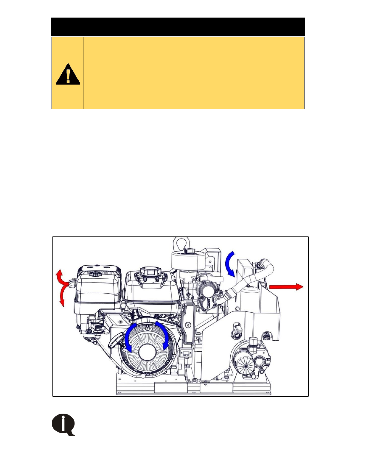
During operation, the Gas Engine Driven 30 CFM Air Compressor generates
a considerable amount of heat that must be evacuated away from the unit for
it to run efficiently. The engine is air cooled and requires an adequate supply
of cool fresh air to cool the engine and allow proper fuel combustion.
Ensure there is a minimum of 6 in of clearance between the engine air intake
(the recoil starter area) and any other components mounted on the vehicle.
The WHASP cooler fan should have a minimum of 12 in of clearance in front
of it, however unobstructed venting to open atmosphere is preferred.
The engine exhaust must be vented away from the Gas Engine Driven 30
CFM Air Compressor and toward a safe location (the exhaust tip can be
rotated to change the exhaust direction if needed). If mounted in an enclosure
(such as the bed of a pickup truck box), the exhaust must be vented outside
of the vehicle to prevent the gas engine from ingesting its exhaust and
overheating or stalling (Figure 8).
Figure 8 – Airflow diagram
Exhaust and waste heat from the Gas Engine Driven 30 CFM Air
Compressor system must be vented away from the system to
prevent the gas engine from ingesting its exhaust and stalling.
Page 23
VMAC – Vehicle Mounted Air Compressors
VMAC Technical Support: 1-888-241-2289
VMAC Knowledge Base: www.kb.vmacair.com
21
Mounting Locations
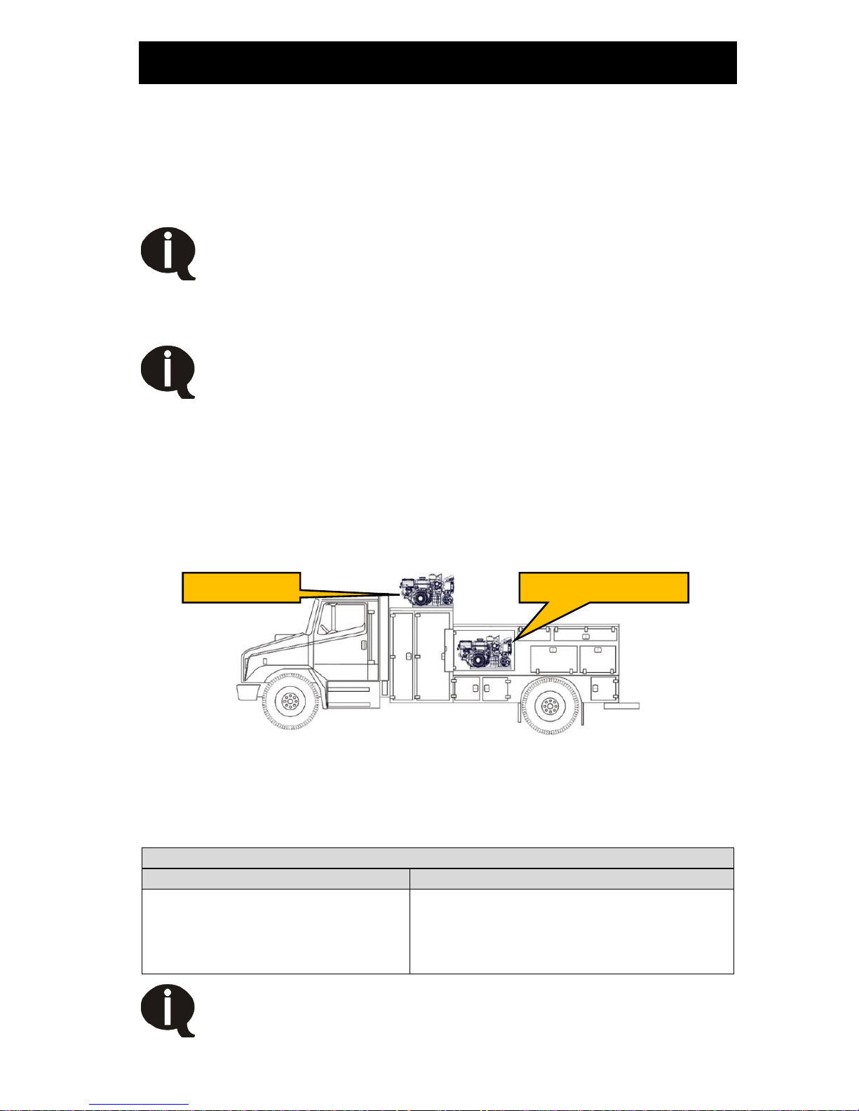
Top Mounting
Top mounted, is the preferred mounting location. Placing the unit on top of
the service body provides the best access to cool fresh air. Maintain a
minimum of 6 in between the sides of the Gas Engine Driven 30 CFM Air
Compressor and 1 ft in front of the WHASP cooling fan and all other solid
objects (Figure 9).
When selecting a top mount location, ensure the fuel shut off
valve is easily accessible. The fuel valve must be shut off
when the unit is not in use, including during transport.
Enclosed Mounting
Enclosed mounting is not recommended due to the significant
heat generated by the unit. As the engine used on the Gas
Engine Driven 30 CFM Air Compressor is air cooled, special
consideration must be given to ensuring an adequate supply
of cool fresh air flows to the engine.
Mounting the Gas Engine Driven 30 CFM Air Compressor in an enclosure will
limit access to cool fresh air, restrict the escape of hot air from around the unit
and have an adverse effect on cooling, engine performance and reduce the
unit’s duty cycle. Ensure adequate ventilation is provided for cooling and to
evacuate the exhaust. If mounting in an enclosure, VMAC strongly
recommends mounting the unit on a pullout drawer and extending the drawer
any time the unit is run.
Figure 9 – Mounting locations
While it is not possible to make absolute recommendations regarding
ventilation due to the widely differing circumstances that are possible, duty
cycle, ambient temperature and enclosure shape are some of the important
variables that must be considered.
Ensure the engine exhaust and hot air generated by the gas
engine and WHASP Tank cooler are routed in such a way as to
prevent recirculation back into the unit.
Minimum considerations for mounting in an enclosure
Supply cool fresh air to:
Exhaust and heat:
• Engine air intake.
• Compressor air intake.
• Compressor cooler.
• Duct the engine exhaust outside of
the enclosure / vehicle.
• Install an exhaust fan to remove
hot air from the enclosure.
Top mounted
Enclosure mounted
Page 24
VMAC – Vehicle Mounted Air Compressors
VMAC Technical Support: 1-888-241-2289
VMAC Knowledge Base: www.kb.vmacair.com
22
Mounting the Compressor
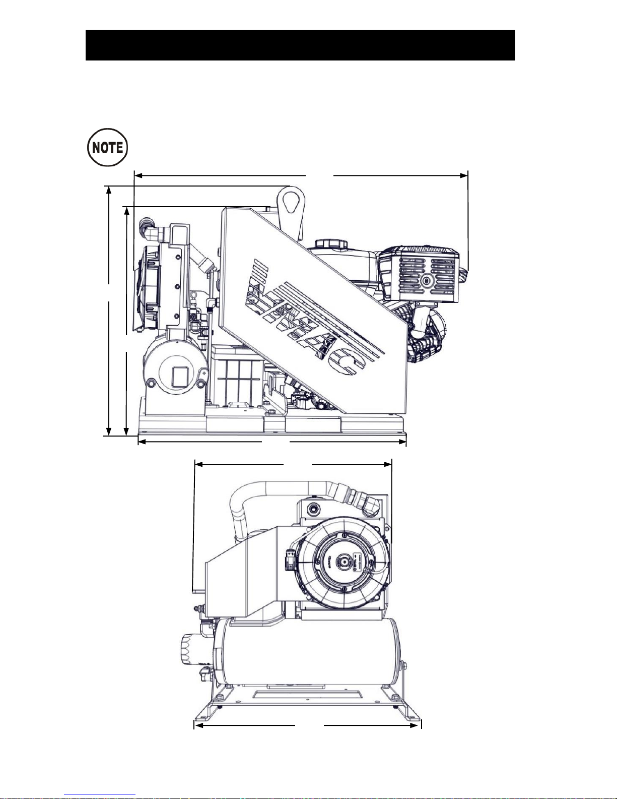
External dimensions with the base plate
Locate a suitable mounting position for the Gas Engine Driven 30 CFM
Air Compressor. Place the unit in its intended location and check for
clearances to any other objects (Figure 10).
All dimensions are in inches.
Figure 10 – External dimensions
25.0
20.7
19.1
23.9
34.0
22.0
Page 25
VMAC – Vehicle Mounted Air Compressors
VMAC Technical Support: 1-888-241-2289
VMAC Knowledge Base: www.kb.vmacair.com
23
Mounting the unit
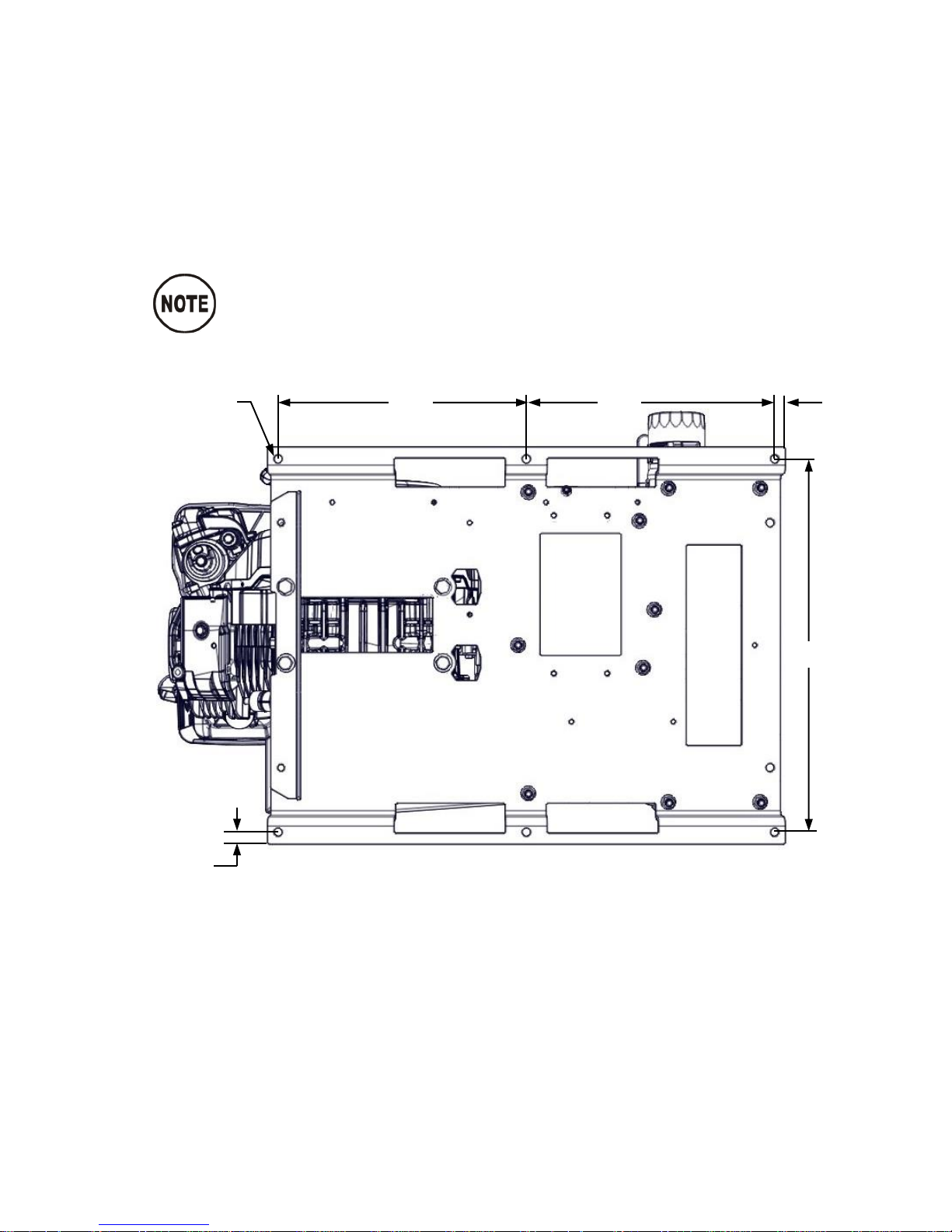
There are 6 holes along the outer flange of the base plate for mounting
the Gas Engine Driven 30 CFM Air Compressor (Figure 11).
Drill 6 holes in the surface that the Gas Engine Driven 30 CFM Air
Compressor will be mounted to. Use a minimum of (6x) 3/8 in or M10
fasteners. Ensure washers are used in addition to locknuts or Loctite 242
(blue) on the mounting fasteners.
Connect the downstream plumbing to the ball valve outlet.
All dimensions are in inches.
Figure 11 – Base plate mounting configuration
12.0
12.0
0.5
Ø.43 (6x)
18.0
0.56
Page 26
VMAC – Vehicle Mounted Air Compressors
VMAC Technical Support: 1-888-241-2289
VMAC Knowledge Base: www.kb.vmacair.com
24
Before Starting the Gas Engine Driven
30 CFM Air Compressor
Ensure the following has been completed before operating the
Gas Engine Driven 30 CFM Air Compressor:
Check the compressor oil level and condition (Page 42).
New VMAC oil is clear and may be difficult to see in the sight
glass.
Inspect the blowdown muffler (Page 43).
Inspect the Pressure Relief Valve (Page 44).
Inspect the compressor air filter (Page 45).
Inspect the engine air filter (See the Honda Owner’s Manual).
Check the engine oil level and condition (See the Honda Owner’s
Manual).
Check the fuel level.
Do a final inspection to ensure that all fasteners and connections are
tight.
Check that all hoses and wiring is secure and adequately protected.
Check for any fluid leaks around the unit.
Ensure any pneumatic equipment is securely connected and the
discharge ball valve is closed.
If the system has been run, ensure the compressor system
has depressurized prior to restarting. The engine will not be
able to start if the system is still under pressure.
Page 27
VMAC – Vehicle Mounted Air Compressors
VMAC Technical Support: 1-888-241-2289
VMAC Knowledge Base: www.kb.vmacair.com
25
Starting and Stopping the Engine
Starting the engine with the key switch
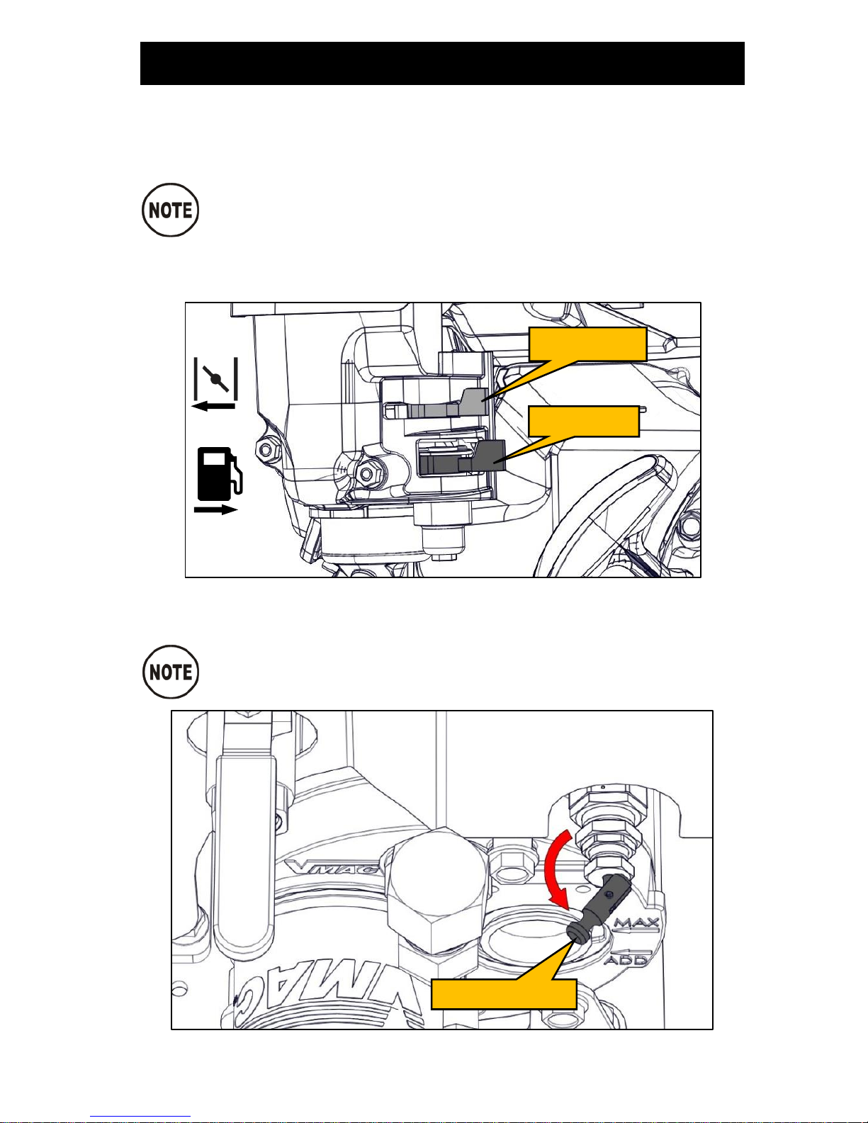
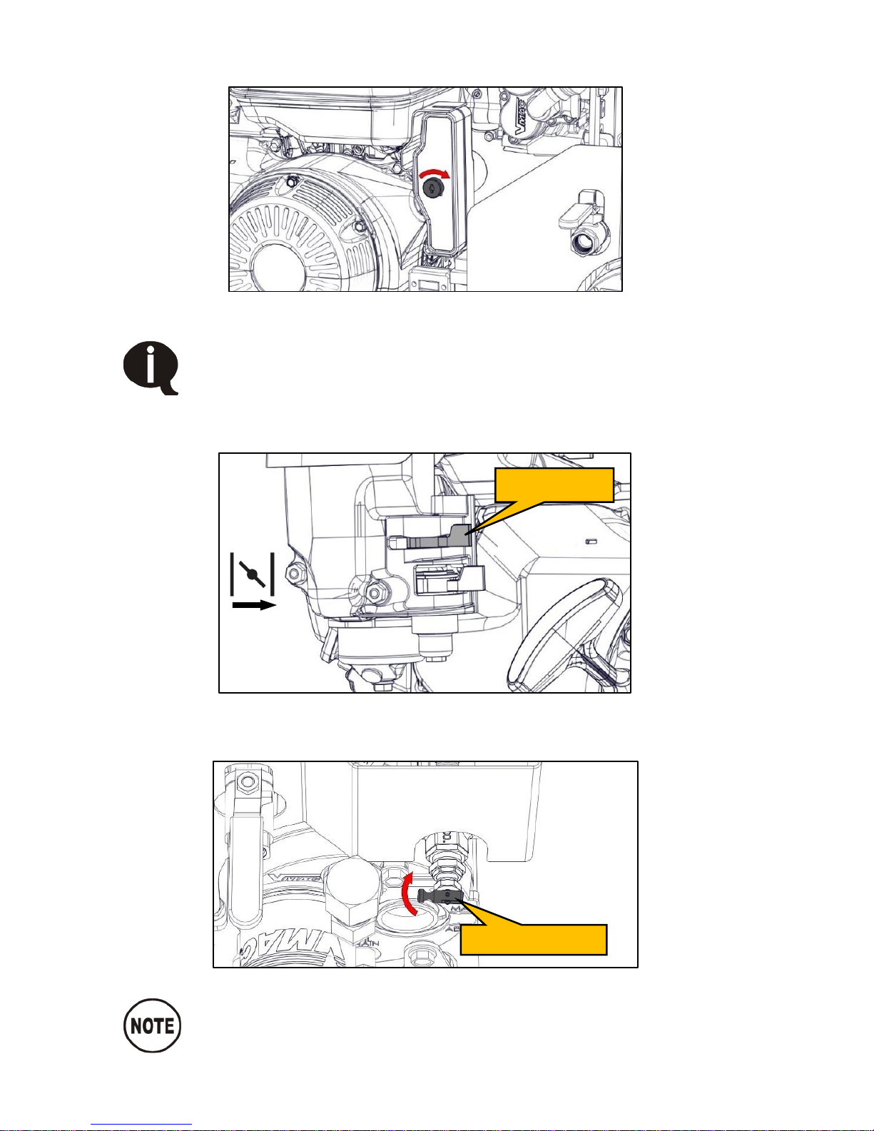
1)
If the engine is cold, close the choke by moving the choke lever all the
way to the left.
The choke may not be necessary on warm days or when the
unit has already been running.
To start a warm engine, ensure the choke is open by
confirming the lever is all the way to the right.
2)
Turn on the fuel by moving the fuel shut off lever all the way to the right
(Figure 12).
Figure 12 – Fuel and choke levers
3)
Actuate the unloader valve by pulling out the handle (Figure 13).
The unloader valve should be opened to reduce the load on the
engine during warm up.
Figure 13 – Unloader valve
Fuel lever
Choke lever
Unloader valve
ON
ON
Page 28
VMAC – Vehicle Mounted Air Compressors
VMAC Technical Support: 1-888-241-2289
VMAC Knowledge Base: www.kb.vmacair.com
26
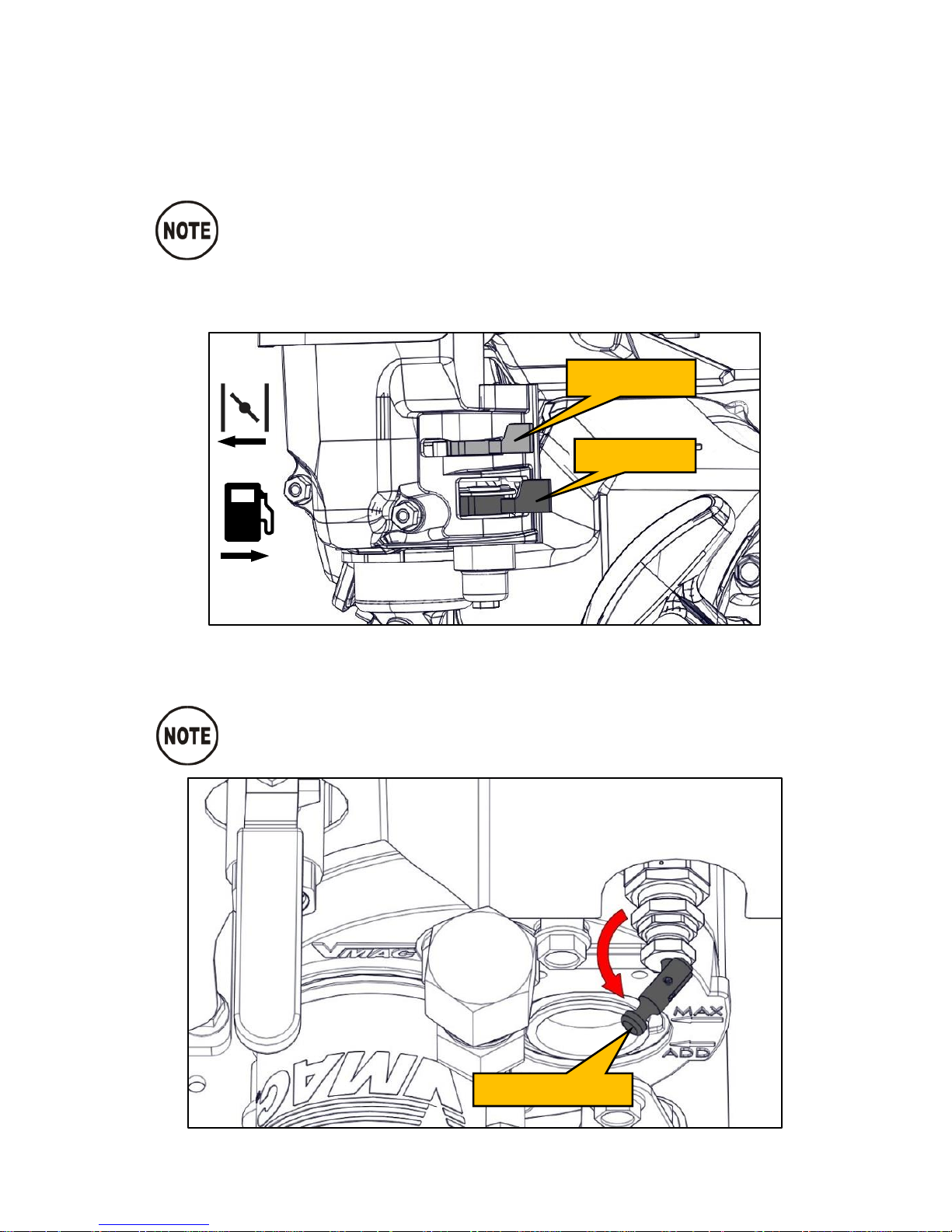
4)
Turn the ignition key switch to the “START” position and hold it there until
the engine starts (maximum of 5 seconds) (Figure 14).
Figure 14 – Key switch
If the engine fails to start within 5 seconds, release the key and
wait at least 10 seconds before operating the starter again.
Using the starter for more than 5 seconds at a time will
overheat the starter motor and may damage it.
5)
Once the engine is running, gradually open the choke by moving the
choke lever to the right as the engine warms up (Figure 15).
Figure 15 – Choke
6)
Once the engine has reached normal operating temperature, release the
tension on the unloader valve (Figure 16).
Figure 16 – Unloader valve
While the unloader valve is actuated the system will only build
to 40 psi. Once the engine has warmed up, close the unloader
valve to allow the system to build to full system pressure.
Choke lever
Off
Unloader valve
Page 29
VMAC – Vehicle Mounted Air Compressors
VMAC Technical Support: 1-888-241-2289
VMAC Knowledge Base: www.kb.vmacair.com
27
Starting the engine with the recoil starter (pull
cord)
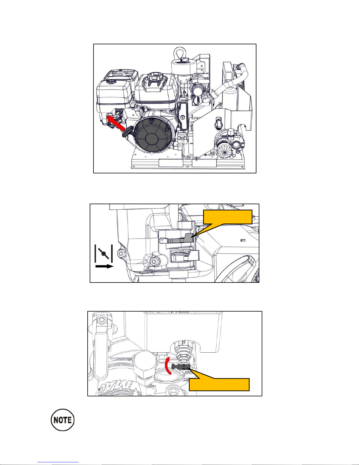
1)
Turn the ignition key switch to the “ON” position.
2)
If the engine is cold, close the choke by moving the choke lever all the
way to the left.
The choke may not be necessary on warm days or when the
unit has already been running.
To start a warm engine, ensure the choke is open by
confirming the lever is all the way to the right.
3)
Turn on the fuel by moving the fuel shut off lever all the way to the right
(Figure 17).
Figure 17 – Fuel and choke levers
7)
Actuate the unloader valve by pulling out the handle (Figure 18).
The unloader valve should be opened to reduce the load on the
engine during warm up.
Figure 18 – Unloader valve
Fuel lever
Choke lever
ON
Unloader valve
ON
Page 30
VMAC – Vehicle Mounted Air Compressors
VMAC Technical Support: 1-888-241-2289
VMAC Knowledge Base: www.kb.vmacair.com
28
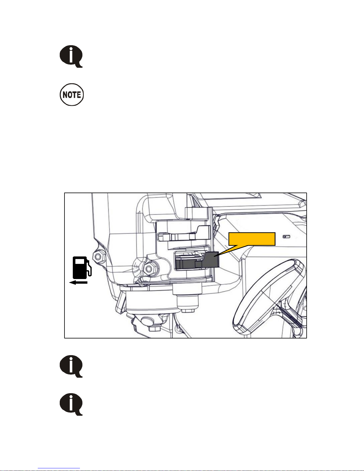
4)
Pull the starter grip lightly until resistance is felt, then pull briskly in the
direction of the arrow. Return the starter grip gently to prevent damage to
the starter (Figure 19).
Figure 19 – Key switch
8)
Once the engine is running, gradually open the choke by moving the
choke lever to the right as the engine warms up (Figure 20).
Figure 20 – Choke
9)
Once the engine has reached normal operating temperature, release the
tension on the unloader valve (Figure 21).
Figure 21 – Unloader valve
While the unloader valve is actuated the system will only build
to 40 psi. Once the engine has warmed up, close the unloader
valve to allow the system to build to full system pressure.
Choke lever
Off
Unloader valve
Page 31
VMAC – Vehicle Mounted Air Compressors
VMAC Technical Support: 1-888-241-2289
VMAC Knowledge Base: www.kb.vmacair.com
29
Stopping the engine
The engine may experience a backfire if it is shut off while the
engine speed is above idle and the compressor is building air
pressure. This is normal and is caused by the load on the
engine during shut down. Ensure the engine is at idle prior to
shutting it off.
The exhaust system is equipped with a spark arrester.
To properly shut down the engine:
1)
Stop air use and close the air discharge valve.
2)
Ensure the system has built to full system pressure (factory setting 150
psi) and the compressor is “unloaded”.
3)
Allow the engine to run at low idle for at least 10 seconds.
4)
Turn the key to the “OFF” position.
5)
Move the fuel shut off valve all the way to the left to shut off the fuel
(Figure 22)
Figure 22 – Shut off fuel
Improper shut down may cause compressor oil to discharge
from the compressor air filter.
Ensure the fuel shut off valve is closed (all the way to the left)
when the unit is not being run or before moving to a different
site. Failure to do this may allow fuel to overfill the carburetor
float bowl and flow into the engine’s cylinder and/or crank case
causing the engine to hydraulically lock.
Off
Fuel lever
Page 32

VMAC – Vehicle Mounted Air Compressors
VMAC Technical Support: 1-888-241-2289
VMAC Knowledge Base: www.kb.vmacair.com
30
Recommended Accessories
While the compressor system will function without the following accessories,
VMAC strongly recommends their use for optimal performance.
Receiver Tank
A receiver tank reduces the duty cycle of the compressor, and can help the
Gas Engine Driven 30 CFM Air Compressor run tools with higher cfm
requirements. It can also provide a buffer so that tools can be used
immediately upon system start up.
For information on installing an air receiver tank see the “Air Receiver Tank”
section of this manual on page 31.
Air receiver tanks are available for purchase through VMAC. See the
“Accessory Product” section of this manual on page 34 for more information.
Pressure Gauge
While not critical to system performance, a pressure gauge is important for
fine tuning the system and simplifies any potential troubleshooting.
Install a 200 psi pressure gauge downstream of the air discharge valve.
Pressure Regulator and/or Lubricator or FRL
The compressor can produce air pressures up to approximately 150 psi
(1035 kPa). It is the responsibility of the user to know the pressure and air flow
requirements of the tools powered by the air compressor system.
An appropriate air pressure regulator and lubricator can be installed
downstream of the air discharge valve. Failure to regulate the air pressure may
cause damage to the tool.
FRL’s are available for purchase through VMAC. See the “Accessory
Product” section of this manual on page 34 for more information.
Page 33
VMAC – Vehicle Mounted Air Compressors
VMAC Technical Support: 1-888-241-2289
VMAC Knowledge Base: www.kb.vmacair.com
31
Air Receiver Tank
Pressure in the air receiver tank will not be relieved when the
compressor system blows down. This is normal operation.
Prior to performing any service work on the system, relieve
the pressure in the air receiver tank.
The VMAC WHASP Tank has a built-in check valve. Use of an
additional check valve is not required and may cause erratic
performance.
If an air receiver tank will be used with this system, the
following instructions must be followed to prevent damage
to the system.
When connecting a large capacity receiver tank, users may
experience situations where the system does not unload
after reaching 150 psi (See the “System Pressure Unload”
section on page 12 for more information). If this happens, the
regulator on the inlet valve may need to be adjusted. See
page 68 for instructions.
An air receiver tank provides a buffer as it gives the compressor time to react
by increasing the engine speed and producing air before the tool stalls. It also
has the advantage of lowering the duty cycle of the compressor system.
The VMAC compressor system automatically depressurizes when it is shutdown. The VMAC WHASP Tank has a one-way check valve installed from the
factory which prevents the compressed air and any moisture in receiver tank
from traveling back into the WHASP Tank.
Installation of an additional one-way check valve may cause erratic
performance (Figure 23).
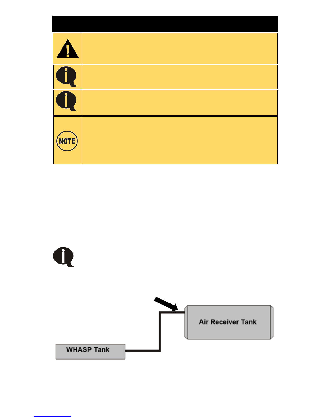
The line to the air receiver tank must be installed as high as
possible to prevent water from entering the line.
Figure 23 – Air receiver tank
Install the line to the air
receiver tank as high as
possible
Page 34
VMAC – Vehicle Mounted Air Compressors
VMAC Technical Support: 1-888-241-2289
VMAC Knowledge Base: www.kb.vmacair.com
32
Setup, Performance Testing and
Adjustments
This system has been adjusted at the factory for general operation.
System operation can be tested using the tools that will be operated by the
system or by using the VMAC Test Tool (A700052) with the 30 cfm (1/8 in)
orifice in the outlet to simulate tool use (Figure 24).
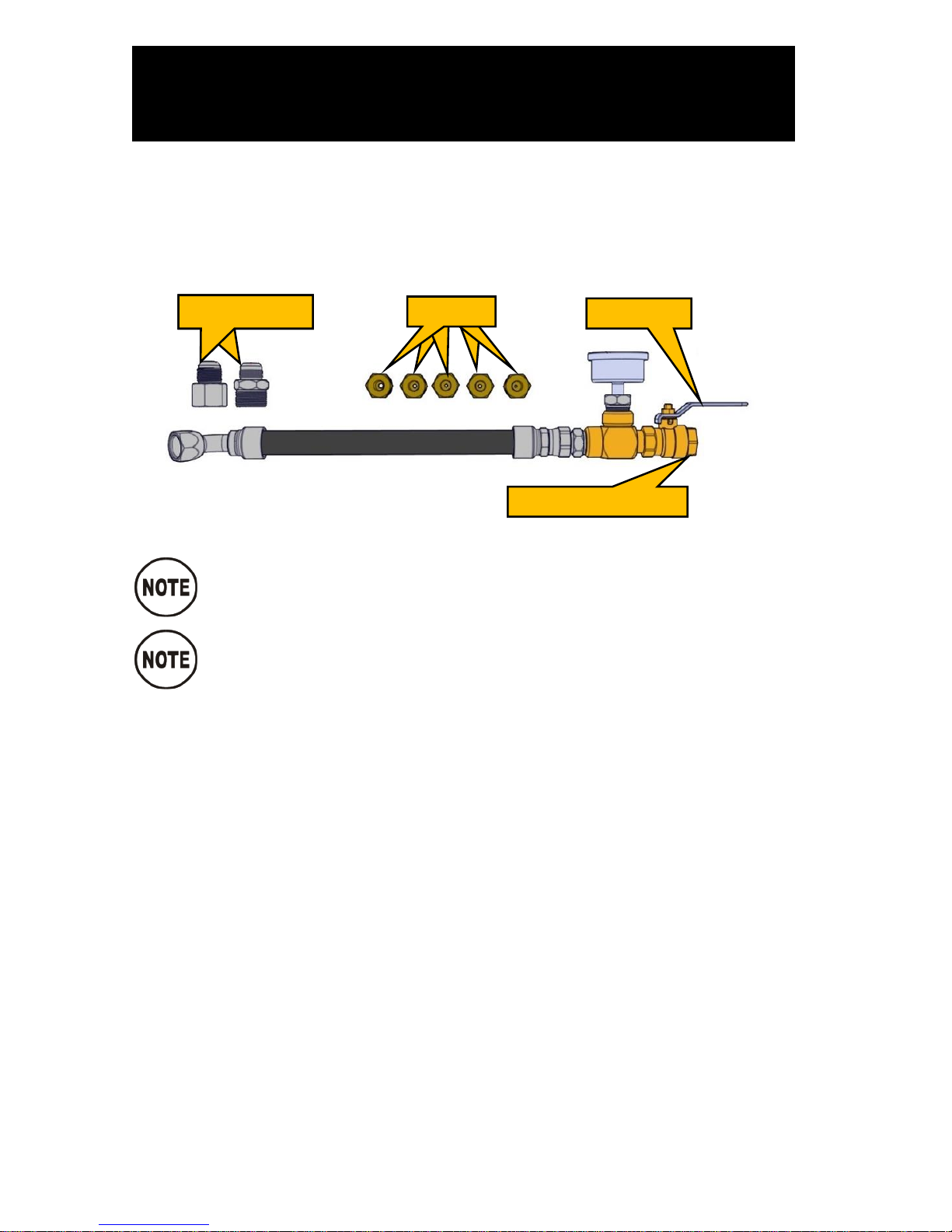
Figure 24 – A700052 Test Tool
Ensure there are no leaks in the test tool. The system may not
idle down or unload if there are leaks in the lines or fittings.
Disconnect all downstream equipment (hose reels, etc.) and
remove the ball valve from the compressor discharge. Connect
the test tool directly to the discharge fitting on the WHASP
Tank.
Install the VMAC test tool at the system outlet with the 30 cfm (1/8 in)
orifice.
Ensure that the ball valve on the test tool is closed.
Start the compressor system and allow the engine to run until it is at
operating temperature.
Ensure the tension on the unloader valve is released to allow the
compressor to build to full pressure.
Observe the pressure gauge, it should indicate approximately 150 psi
(factory setting).
Slowly open the ball valve on the test tool and observe the operation. The
engine speed should increase when the pressure drops to 130 psi (20 psi
below system pressure).
With the ball valve fully open, the pressure should stabilize at
approximately 100 psi (this simulates a tool operating at 30 cfm).
Close the ball valve to allow the system pressure to rise.
Once testing is complete, follow the normal shut off procedure.
JIC adaptors
Orifice
Ball valve
Install orifice here
Page 35

VMAC – Vehicle Mounted Air Compressors
VMAC Technical Support: 1-888-241-2289
VMAC Knowledge Base: www.kb.vmacair.com
33
Engine rpm Adjustment
Adjusting the engine speed is not an approved procedure.
Any damage or performance issues caused by unauthorized
engine rpm adjustment will not be covered under warranty.
Lowering the engine rpm will decrease the cfm output and
will cause the engine to stall, while increasing the engine
rpm may damage the engine.
The engine “low idle” and “high idle” screws are set at the factory and do not
require adjustment. The throttle actuator will automatically raise and lower the
engine speed dependant upon air demand.
Page 36
VMAC – Vehicle Mounted Air Compressors
VMAC Technical Support: 1-888-241-2289
VMAC Knowledge Base: www.kb.vmacair.com
34
Accessory Products from VMAC
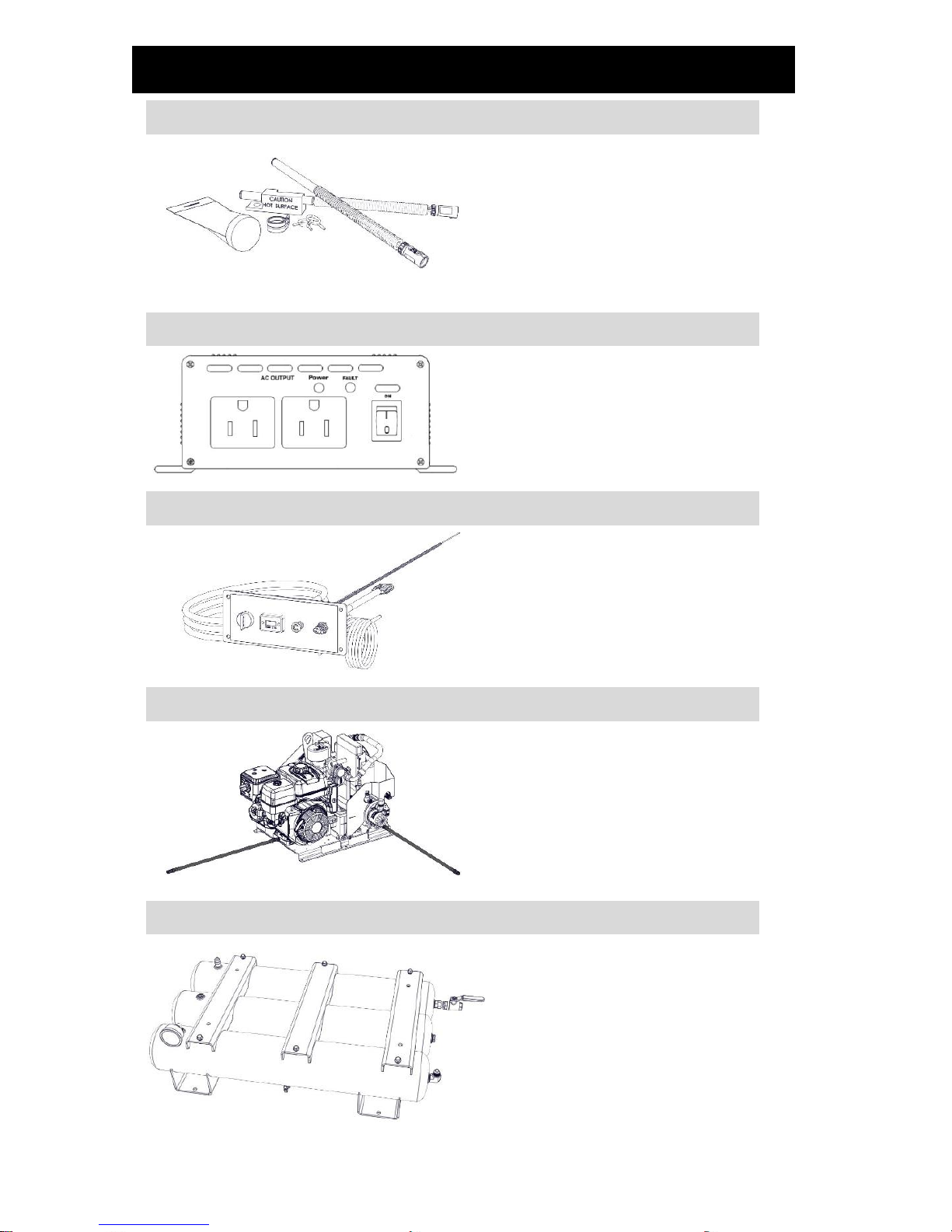
Cold Climate Kit
Part number: A500044; A520004 (factory
installed)
Cold climate heater package for operating
the Gas Engine Driven 30 CFM Air
Compressor in cold climates; proven at
temperatures of -30 °C (-22 °F);
(2x) 120 V AC Heaters; requires 600 W
total power.
600 W Power Inverter
Part number: A500181
600 W, 12 V power inverter; required to
power the Gas Engine Driven 30 CFM Air
Compressor Cold Climate Kit.
Remote Control Panel
Part number: A500042
Remote control panel with a 10 ft
(304.8 cm) extension for key switch, hour
meter, choke and unloader valve.
Remote Oil Drain
Part number: A500043
(2x) 3 ft (91.5 cm) remote drain hoses to
allow the engine and compressor oil to be
easily drained away from the engine.
Triple 4 Gallon Low Profile Air Receiver Tanks
Part number: A500188; (A520005
factory installed)
Triple 4 gallon air receiver tanks with
mounting frame; includes 200 psi
pressure gauge, hose, ball valve and
drain valves.
• Max pressure: up to 150 psi
• Dimensions: 35.0 in (88.9 cm) L x
20.5 in (52.0 cm) W x 8.4 in
(21.3 cm) H
• Weight: 80 lb (36 kg)
Page 37
VMAC – Vehicle Mounted Air Compressors
VMAC Technical Support: 1-888-241-2289
VMAC Knowledge Base: www.kb.vmacair.com
35
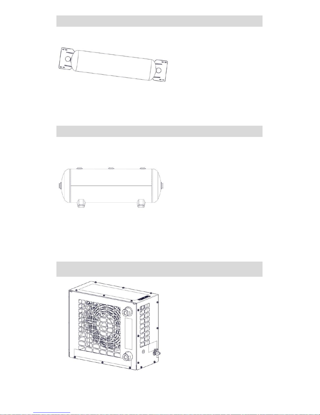
6 Gallon Air Receiver Wing Tank
Part number: A300045
Air receiver tanks are used for lowering
compressor duty cycle and removing
water from compressed air;
recommended for optimum operation of
all VMAC Gas Driven, Diesel Driven,
Hydraulic, and UNDERHOOD30 air
compressors. Manufactured to FMVSS
121 standard; includes fittings, 160 psi
pressure relief valve, and tank drain.
• Max pressure: up to 150 psi
• Dimensions: 32 in (81.3 cm) L x
8 in (20.3 cm) D
• Weight: 23 lb (10.4 kg)
10 Gallon Air Receiver Tank w/ Mounting Feet
Part number: A300047
Air receiver tanks are used for lowering
compressor duty cycle and removing
water from compressed air.
Recommended for optimum operation of
VMAC Hydraulic Air Compressors,
VMAC Diesel Driven Air Compressors,
VMAC UNDERHOOD70 – Green Series
Air Compressors, and VMAC
Multifunction Power Systems, which
include standby mode; ASME certified;
includes fittings, 200 psi pressure relief
valve, tank drain, and 200 psi pressure
gauge.
• Max pressure: up to 200 psi
• Dimensions: 30 in (76.2 cm) L x
10 in (25.4 cm) D
• Weight: 33 lb (15 kg)
Air Aftercooler
Part number: A800070
Improves tool performance and extends the
life of air tools; removes up to 80% of water
from compressed air; includes automatic
water drain.
• Max air flow: 70 cfm / 175 psi
• Port size: 3/4 in NPT inlet and outlet
• Electrical: 12 V
• Dimensions: 17 in (43.2 cm) L x 8.0 in
(20.3 cm) W x 14.5 in (36.8 cm)
HWeight: 35 lb (15.8 kg)
Page 38
VMAC – Vehicle Mounted Air Compressors
VMAC Technical Support: 1-888-241-2289
VMAC Knowledge Base: www.kb.vmacair.com
36
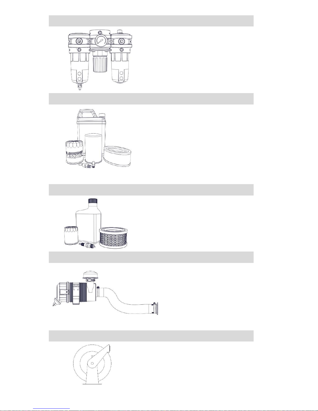
Filter Regulator Lubricator (FRL) – 70 cfm
Part number: A700151
Extends the life of air tools; filter removes
contaminants from the compressed air,
adjustable regulator can reduce air pressure
going to tools, lubricator adds atomized tool
oil to the air stream to lubricate air tools
(Tool oil not included).
• Max air flow: up to 70 cfm / 150 psi
• Port size: 3/4 in NPT inlet and outlet
Compressor Service Kits
200 Hour or 6 Month Service Kit -
Part number: A700219
Includes 4 L VMAC high performance
compressor oil, oil filter, air filter, and next
service due decal.
400 Hour or 1-Year Service Kit -
Part number: A700220
Includes 4 L VMAC high performance
compressor oil, oil filter, air filter, spin-on oil
separator, safety valve, muffler, and next
service due decal.
Honda Engine Service Kit
Part number: A500045
300 hour Honda engine tune-up kit
includes 2 L 10W30 oil, dual element air
filter and spark plug. Using OEM service
products will extend the life of the
system.
Heavy Duty Compressor Air Filter
Heavy Duty Air Filter w/ Rain Cap
Part number: A700136
Heavy duty compressor air filter for
moderate dust environments.
Heavy Duty Air Filter w/ Pre-cyclonic
Filter
Part number: A700138
Heavy duty compressor air filter for
moderate and heavy dust environments.
1/2 in x 50 ft Hose Reel
Part number: A700007
Spring-loaded 1/2 in x 50 ft hose reel;
steel construction; full flow shaft and
swivel for maximum performance.
Page 39
VMAC – Vehicle Mounted Air Compressors
VMAC Technical Support: 1-888-241-2289
VMAC Knowledge Base: www.kb.vmacair.com
37
General Maintenance Information
Routine Maintenance
In order to maintain the VMAC warranty, VMAC’s maintenance schedule must
be followed. Only genuine original VMAC replacement parts can be used to
maintain the system.
The compressor system does not contain reed valves or other easily fouled,
fatigue prone components. With proper maintenance, the likelihood of
premature failure or component replacement can be drastically reduced.
The most critical aspect of maintenance is proper air filtration and clean oil. If
any particles enter the compressor, they can score the rotors and
contaminate the roller bearings in the compressor. Any contamination will
cause rapid and severe damage to components.
The Gas Engine Driven 30 CFM Air Compressor must be run a
minimum of once every 30 days for at least 30 minutes to
prevent impact damage and premature bearing failure in the
compressor due to vibration from the vehicle. Regularly
running the system will also help to vaporise and exhaust any
water that has condensed and accumulated in the WHASP
Tank.
Refer to the Honda Owner’s Manual for detailed information
related to the Honda GX390 maintenance schedule.
Torque Specifications
All fasteners must be torqued to specifications. Use manufacturers’ torque
values for OEM fasteners. Apply Loctite 242 (blue) or equivalent on all
engine mounted fasteners. Torque values are with Loctite applied unless
otherwise specified.
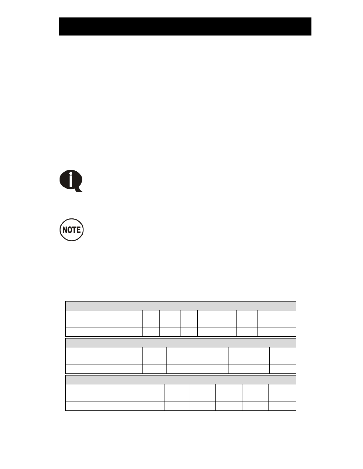
STANDARD GRADE 8 NATIONAL COARSE THREAD
Size
1/4
5/16
3/8
7/16
1/2
9/16
5/8
3/4
Foot-pounds (ft•lb)
9
18
35
55
80
110
170
280
Newton meter (N•m)
12
24
47
74
108
149
230
379
STANDARD GRADE 8 NATIONAL FINE THREAD
Size
3/8
7/16
1/2
5/8
3/4
Foot-pounds (ft•lb)
40
60
90
180
320
Newton meter (N•m)
54
81
122
244
434
METRIC CLASS 10.9
Size
M6
M8
M10
M12
M14
M16
Foot-pounds (ft•lb)
4.5
19
41
69
104
174
Newton meter (N•m)
6
25
55
93
141
236
Table 1 – Torque Table
Page 40
VMAC – Vehicle Mounted Air Compressors
VMAC Technical Support: 1-888-241-2289
VMAC Knowledge Base: www.kb.vmacair.com
38
Maintenance and Repair Safety
It is impossible to warn of all the possible hazards that may
result from operating, servicing, or repairing this system.
Wear all appropriate Personal Protective Equipment and
follow all industry standard safety practices.
Confirm that the system is depressurized and has cooled
prior to performing any service work.
Never use flammable solvents to clean any components. If a
flammable solvent has been used, rinse the component
thoroughly with water and dry it before reinstalling it, to
prevent the possibility of explosion.
Use only genuine VMAC replacement parts to maintain the
system.
Genuine VMAC replacement parts are designed to work with
the high pressure and heat generated by the compressor.
Substituting genuine VMAC replacement parts will void the
warranty and could fail causing equipment damage, injury, or
death.
This information is intended for people with mechanical
trade certification who have the tools and equipment to
properly and safely perform the service or repair. Do not
attempt to service or repair this system without the
appropriate mechanical training, knowledge and experience.
Follow all safety precautions and industry standard “best
practices”.
The negative battery cable and spark plug wire must be
disconnected prior to performing any service or repair work.
Failure to perform this step may result in the engine starting
unexpectedly if the crankshaft is rotated.
Only reconnect the battery cable and spark plug wire once
service or repair has been completed.
Page 41
VMAC – Vehicle Mounted Air Compressors
VMAC Technical Support: 1-888-241-2289
VMAC Knowledge Base: www.kb.vmacair.com
39
Safety Check List
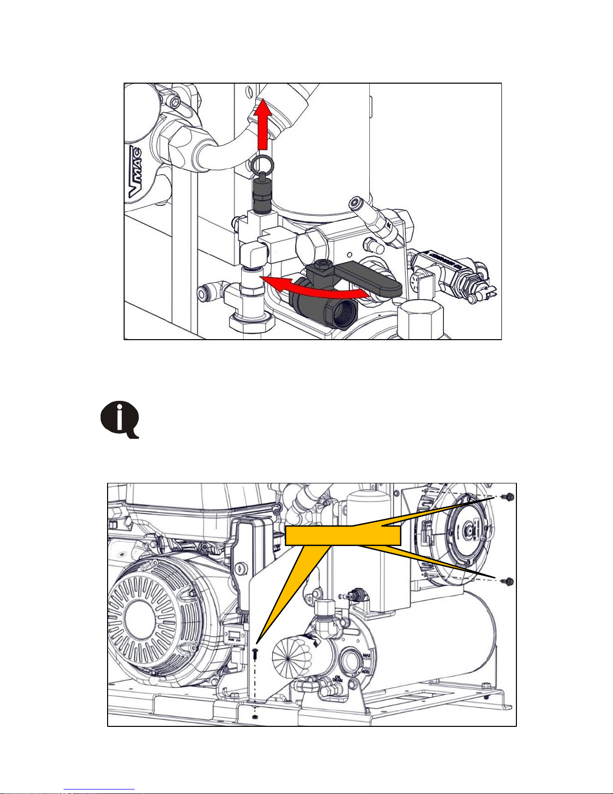
Open the ball valve or connect an air tool to the system to ensure all the
stored air is released (Figure 25).
Figure 25 – Pressure relief valve (shroud removed for clarity)
Gently pull up on the ring on the pressure relief valve to confirm the
system is depressurised (Figure 25).
Do not use the pressure relief valve as a means of
depressurising the compressor system. Doing so will
prematurely wear the internal spring, preventing the valve from
maintaining normal system pressure.
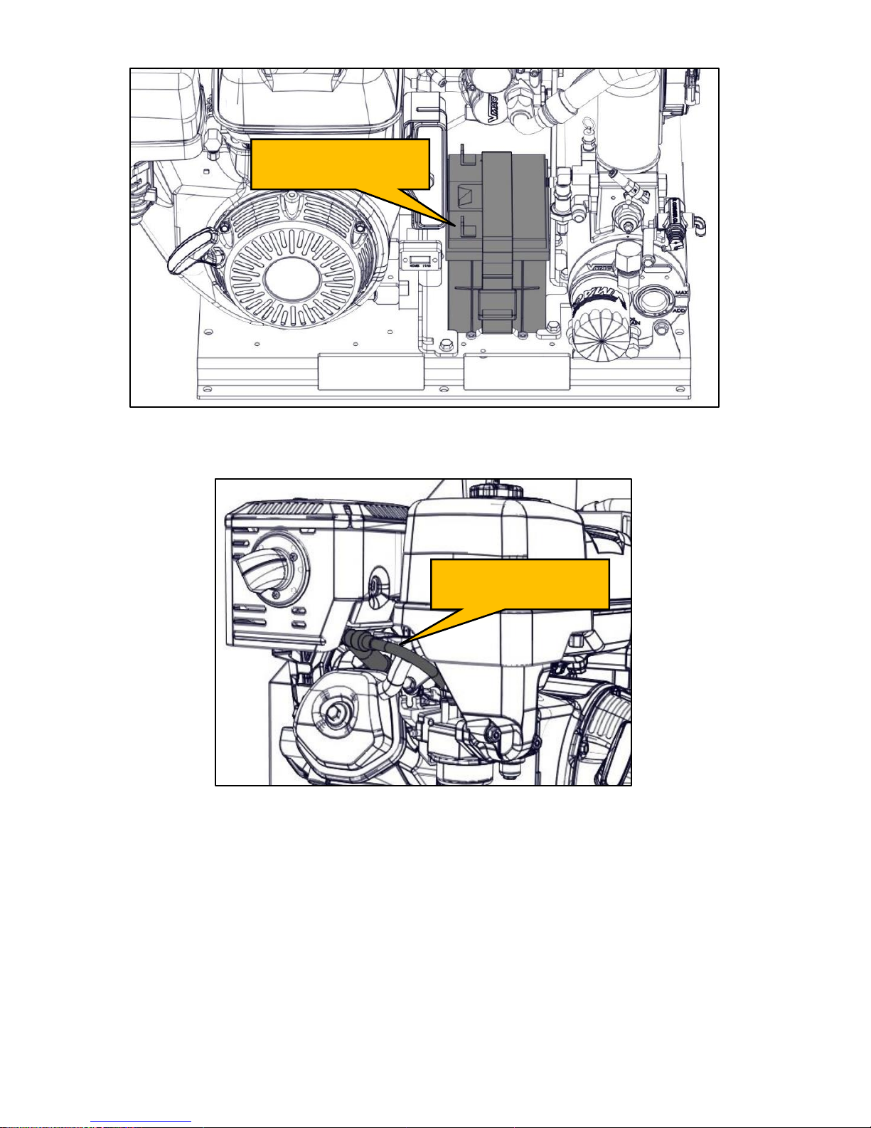
Remove the shroud, there are 3 fasteners that secure it to the base and
WHASP Tank (Figure 26).
Figure 26 – Remove shroud
Remove fasteners
Page 42
VMAC – Vehicle Mounted Air Compressors
VMAC Technical Support: 1-888-241-2289
VMAC Knowledge Base: www.kb.vmacair.com
40
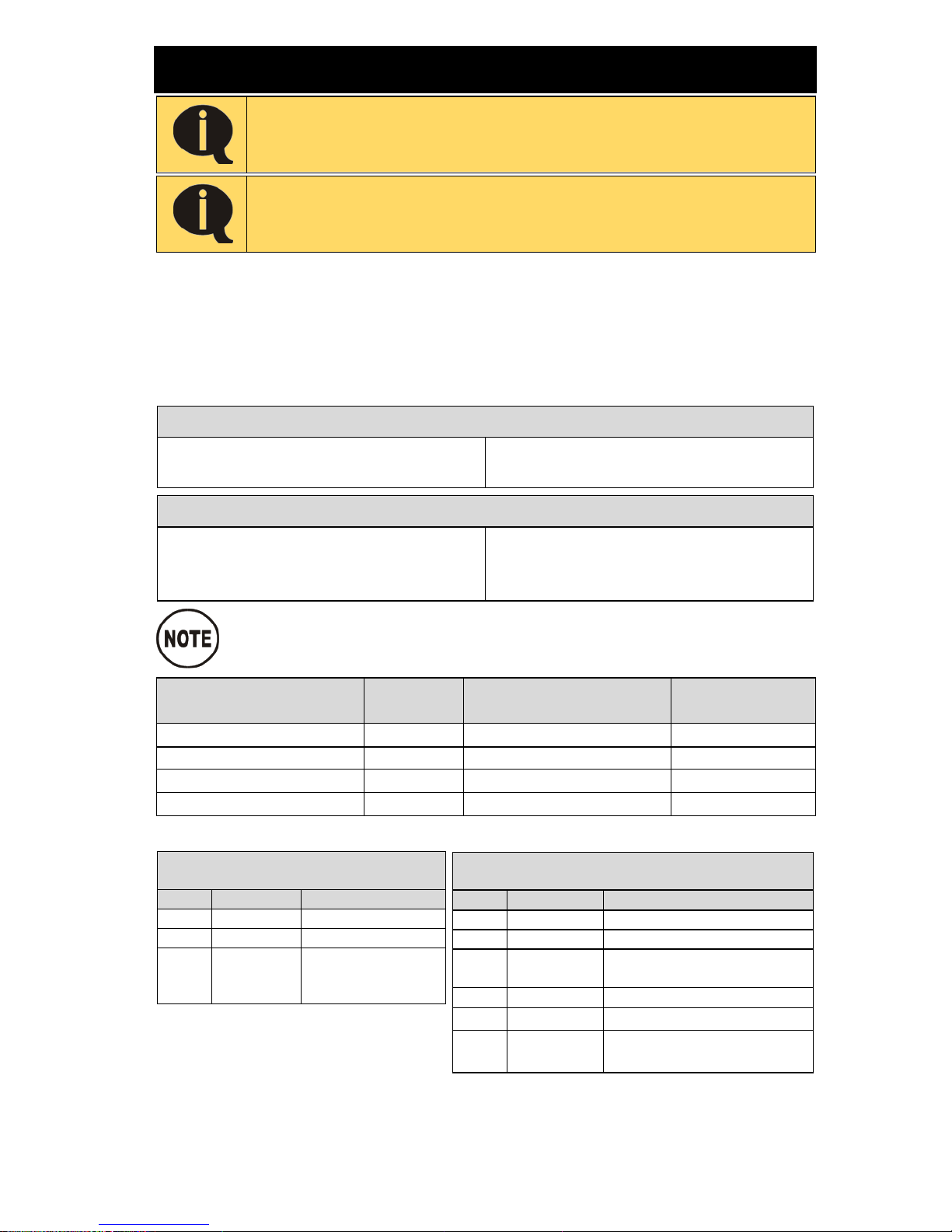
Disconnect the negative battery terminal (Figure 27).
Figure 27 – Negative battery terminal
Disconnect the spark plug wire (Figure 28).
Figure 28 – Spark plug wire
Disconnect negative
battery terminal
Disconnect spark
plug wire
Page 43
VMAC – Vehicle Mounted Air Compressors
VMAC Technical Support: 1-888-241-2289
VMAC Knowledge Base: www.kb.vmacair.com
41
Maintenance Schedule
In order to maintain the warranty on the Gas Engine Driven
30 CFM Air Compressor, use only genuine VMAC and/or
Honda replacement parts to service the system.
Refer to the Honda Owner’s Manual for the engine
maintenance schedule and instructions.
To ensure proper performance and long service life, the following
maintenance schedule must be adhered to.
The hours indicated below are those displayed on the hour meter. Service
should be performed at whichever interval occurs first.
Check the Illustrated Parts List for replacement part numbers or contact
VMAC for more information.
Every 6 months or 200 hours (Service Kit P/N: A700219)
• Change compressor oil.
• Change compressor oil filter.
• Change compressor air filter.
• Inspect pressure relief valve.
Every 12 months or 400 hours (Service Kit P/N A700220)
• Change compressor oil.
• Change compressor oil filter.
• Change compressor air filter.
• Change coalescing filter.
• Change pressure relief valve.
• Change blowdown muffler.
Shorter service intervals are required if the equipment is used
in dusty or extreme working conditions.
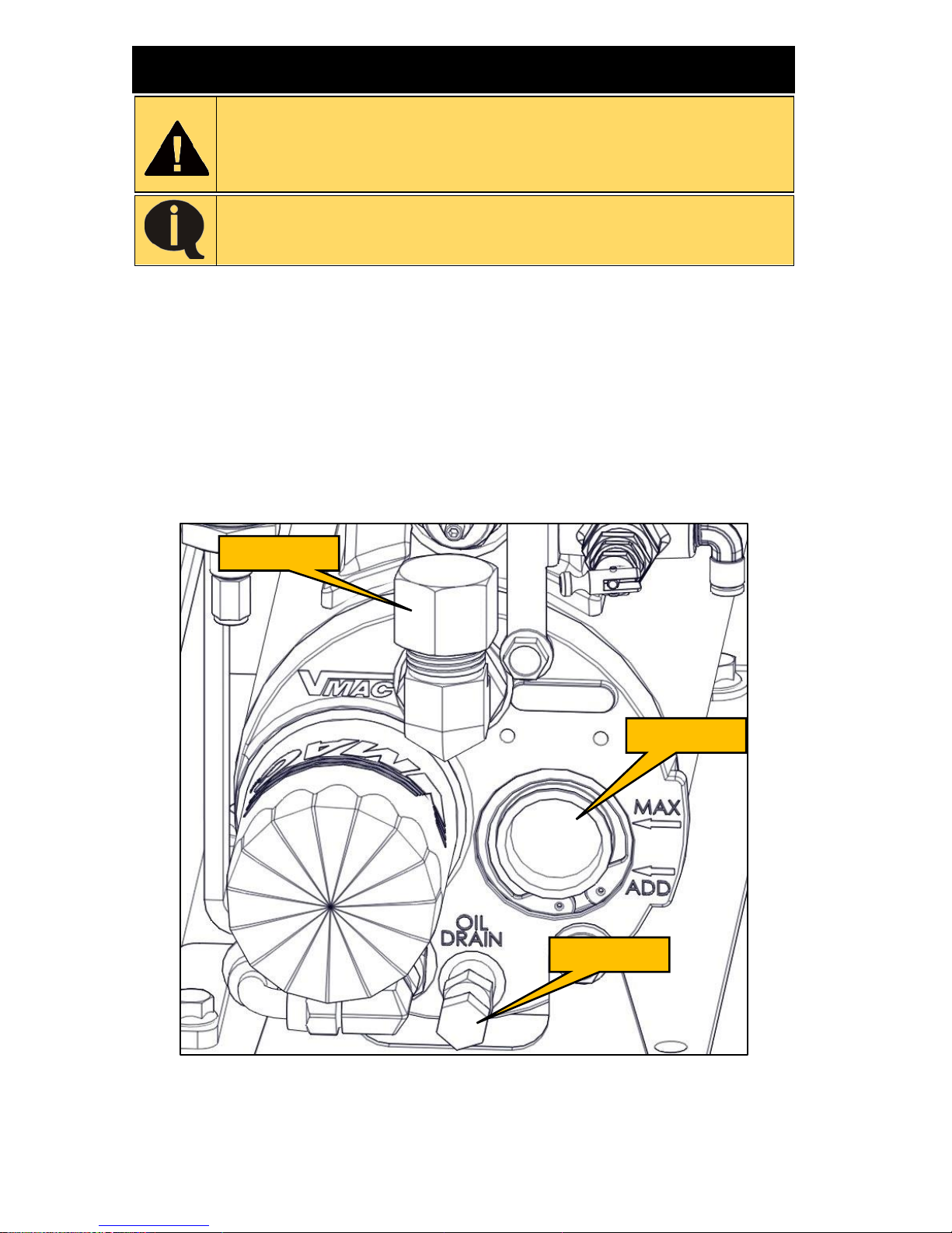
Component
Part
Number
Interval
Extreme
Conditions
Air Filter
3600037
200 hours / 6 months
100 hours
Compressor Oil (4L)
A700094
200 hours / 6 months
100 hours
Oil Filter
9200039
200 hours / 6 months
100 hours
Coalescent Filter
3600088
400 hours / 1 year
200 hours
Table 2 – Service intervals
Table 3 – Service kit contents
400 Hour / 1 Year Service Kit
P/N: A700220
QTY
Part #
Description
1
3600037
Air Filter
1
9200039
Oil Filter
1
A700094
VMAC High Performance
Oil (4 L)
1
3600088
Spin on Coalescing Filter
1
3600054
Valve, safety, 200 psi
1
4500104
Muffler, Sintered Exhaust,
1/8
200 Hour / 6 Month Service Kit
P/N: A700219
QTY
Part #
Description
1
3600037
Air Filter
1
9200039
Oil Filter
1
A700094
VMAC High
Performance Oil
(4 L)
Page 44
VMAC – Vehicle Mounted Air Compressors
VMAC Technical Support: 1-888-241-2289
VMAC Knowledge Base: www.kb.vmacair.com
42
Regular Inspection Instructions
Read the “Maintenance and Repair Safety” section prior to
performing any work on the system (beginning on Page 38).
Wear appropriate Personal Protective Equipment and follow
all industry standard safety practices.
Do not overfill the system. Overfilling the system with oil can
flood the sight glass window and make the system appear
empty.
Inspecting and Adding Compressor Oil
Ensure the vehicle is parked on level ground and that the compressor
system is depressurized and cool to the touch.
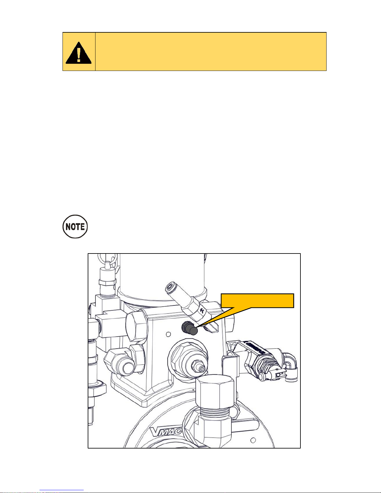
Check the oil level in the sight glass and ensure that it is between the
“MAX” arrow and the “ADD” arrow.
If the level is below the “ADD” arrow:
Remove the fill cap on the tank (above the sight glass).
Using a funnel, pour oil into the fill fitting until the oil level in the sight
glass reaches the “MAX” arrow.
Replace the fill cap and tighten securely.
Figure 29 – Inspecting the oil
Oil fill cap
Sight glass
Oil drain
Page 45
VMAC – Vehicle Mounted Air Compressors
VMAC Technical Support: 1-888-241-2289
VMAC Knowledge Base: www.kb.vmacair.com
43
Inspecting and Replacing the Blowdown Muffler
Read the “Maintenance and Repair Safety” section prior to
performing any work on the system (beginning on Page 38 ).
Wear appropriate Personal Protective Equipment and follow
all industry standard safety practices.
The Blowdown Muffler is a regular service item and must be replaced every
400 hours or 1 year, whichever interval occurs first.
Visually inspect the blowdown muffler for evidence of corrosion or loss of
functionality. Ensure the muffler allows the blowdown to depressurize the
system. To test the blowdown system and muffler:
Turn the system on and allow it reach full system pressure (factory
setting 150 psi).
Turn the ignition key switch to “OFF”.
Listen for the pressurized air to blowdown through the muffler on the
WHASP Tank. Blowdown should be completed in approximately 20
seconds.
If the muffler is showing signs of blockage, contact a local VMAC dealer
for a replacement.
A replacement blowdown muffler is included with the VMAC
400 hour service kit.
Figure 30 – Blowdown muffler (Shroud removed for clarity)
Blowdown muffler
Page 46
VMAC – Vehicle Mounted Air Compressors
VMAC Technical Support: 1-888-241-2289
VMAC Knowledge Base: www.kb.vmacair.com
44
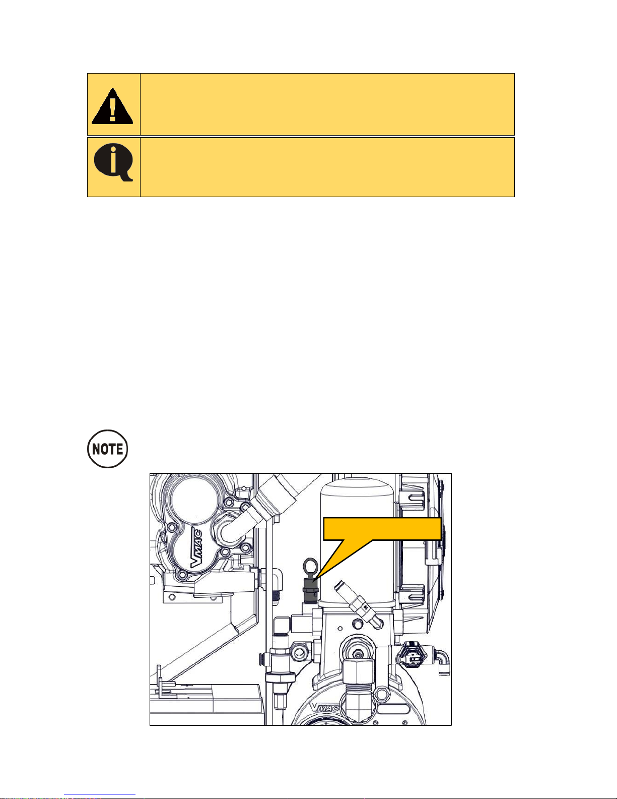
Inspecting and Replacing the Pressure Relief
Valve
Read the “Maintenance and Repair Safety” section prior to
performing any work on the system (beginning on Page 38).
Wear appropriate Personal Protective Equipment and follow
all industry standard safety practices.
Do not use the pressure relief valve as a means of releasing
pressure from the system. Doing so will prematurely wear
the internal spring, preventing the valve from maintaining
normal system pressure.
The Pressure Relief Valve is a regular service item, and must be replaced
every 400 hours or 1 year, whichever interval occurs first.
Inspect the pressure relief valve for signs of corrosion or loss of functionality.
To test the pressure relief valve functionality:
Visually inspect the valve and ensure it is not corroded and that the vent
holes are not plugged.
Turn the system on and allow it reach full system pressure (factory
setting 150 psi).
Ensure that air does not leak out of the valve. Air leaking from the
pressure relief valve when system pressure is at or below 150 psi
indicates that the spring in the valve is worn and the valve must be
replaced.
If the pressure relief valve is showing loss of functionality, contact a local
VMAC dealer for a replacement.
A replacement pressure relief valve is included with the VMAC
400 hour service kit.
Figure 31 – Pressure relief valve (Shroud removed for clarity)
200 psi relief valve
Page 47
VMAC – Vehicle Mounted Air Compressors
VMAC Technical Support: 1-888-241-2289
VMAC Knowledge Base: www.kb.vmacair.com
45
Inspecting and Replacing the Air Filter
Read the “Maintenance and Repair Safety” section prior to
performing any work on the system (beginning on Page 38 ).
Wear appropriate Personal Protective Equipment and follow
all industry standard safety practices.
Clean loose debris from the area around the compressor and the filter
cover to prevent contaminants entering the compressor.
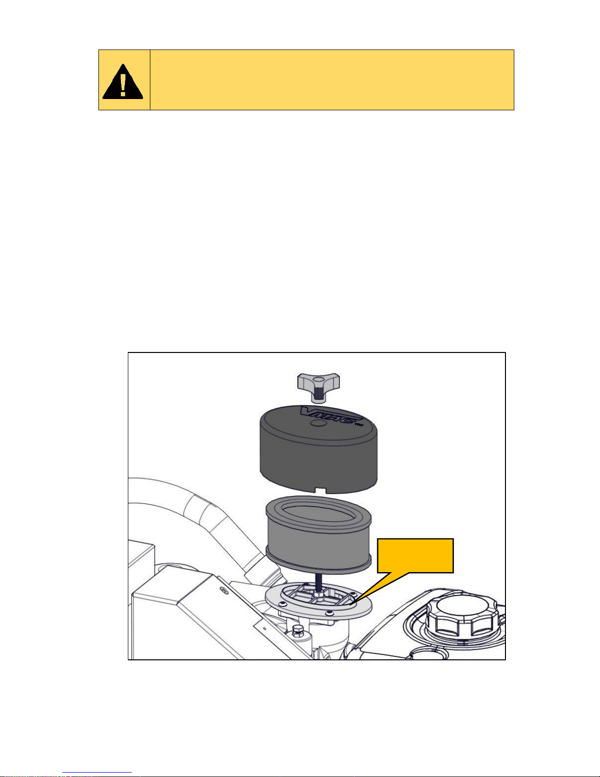
Remove the filter cover retainer knob, the air filter cover and the air filter
element.
Immediately cover the compressor opening with tape or with a clean cloth
to prevent contamination. Do not use compressed air or perform any
other tasks around the compressor until the filter and cover have been
replaced.
Clean the inside of the filter cover with a clean, dry cloth. Do not use
flammable solvents to clean the inside of the cover.
Remove the cloth or tape covering the inlet and install a new air filter.
Ensure the filter fits over the “step” on the filter plate.
Replace the cover and secure it with the filter cover retainer knob. Do not
overtighten.
Figure 32 – Compressor air filter and cover
Filter plate
“step”
Page 48
VMAC – Vehicle Mounted Air Compressors
VMAC Technical Support: 1-888-241-2289
VMAC Knowledge Base: www.kb.vmacair.com
46
Inspecting and Replacing the Drive Belt
Read the “Maintenance and Repair Safety” section prior to
performing any work on the system (beginning on Page 38).
Wear appropriate Personal Protective Equipment and follow
all industry standard safety practices.
Check the drive belt for evidence of glazing, cracks, missing or damaged ribs
or damage to the belt edges and surface. If the drive belt is damaged, install a
new drive belt.
Inspect both pulleys and the idler for damage. If any of the components show
cracks, chipping, impact damage or any other indications of physical damage,
replace the component.
If the damage indicates possible misalignment, check the pulley alignment. If
the pulleys are not properly aligned, check all fasteners to ensure that they
are properly torqued and that there are no loose or worn components.
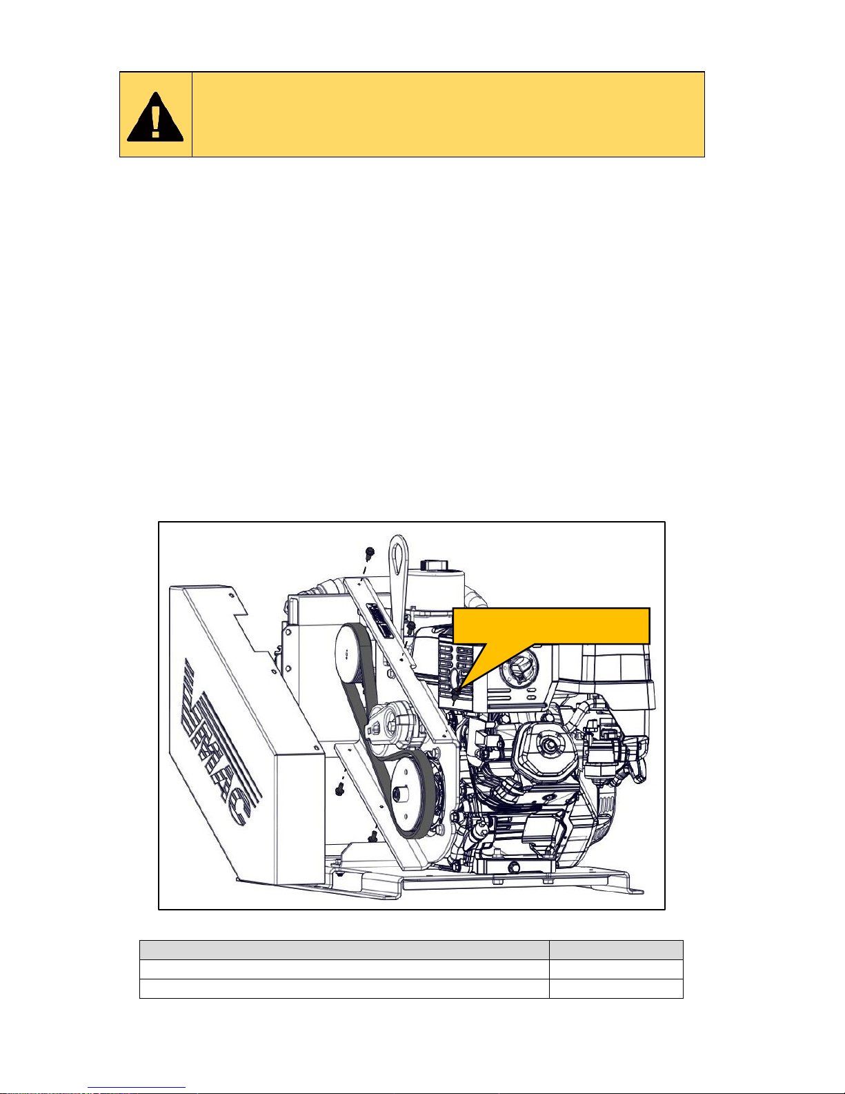
Remove the 5 fasteners from the belt guard and remove the belt guard.
Using a 3/8 in drive, remove tension from the drive belt and discard it.
Install the new drive belt.
Tension the new drive belt.
Apply Loctite 242 (blue) to the 5 fasteners and reinstall the belt guard.
Figure 33 – Inspecting the drive belt
Description
Part Number
Belt (Gates part number K040438)
1620365
Tensioner (Ford part number 7C3Z-6B209-D)
3300036
Table 4 – Belt part numbers and tension
Remove fasteners (5x)
Page 49
VMAC – Vehicle Mounted Air Compressors
VMAC Technical Support: 1-888-241-2289
VMAC Knowledge Base: www.kb.vmacair.com
47
Inspecting and Replacing the PTFE Tubes and
Push-To-Connect Fittings
Read the “Maintenance and Repair Safety” section prior to
performing any work on the system (beginning on Page 38 ).
Wear appropriate Personal Protective Equipment and follow
all industry standard safety practices.
The scavenge, pressure control and throttle control tubes are made of
Polytetrafluoroethylene (PTFE) and are within specification to work with
VMAC compressor oil and to withstand the high pressure and operating
temperatures generated by the compressor. Standard air brake hose is not a
suitable replacement.
PTFE Tubing must be cut to length using the proper tubing cutter. Side
cutters and other tools tend to leave sharp edges and crush the tubing.
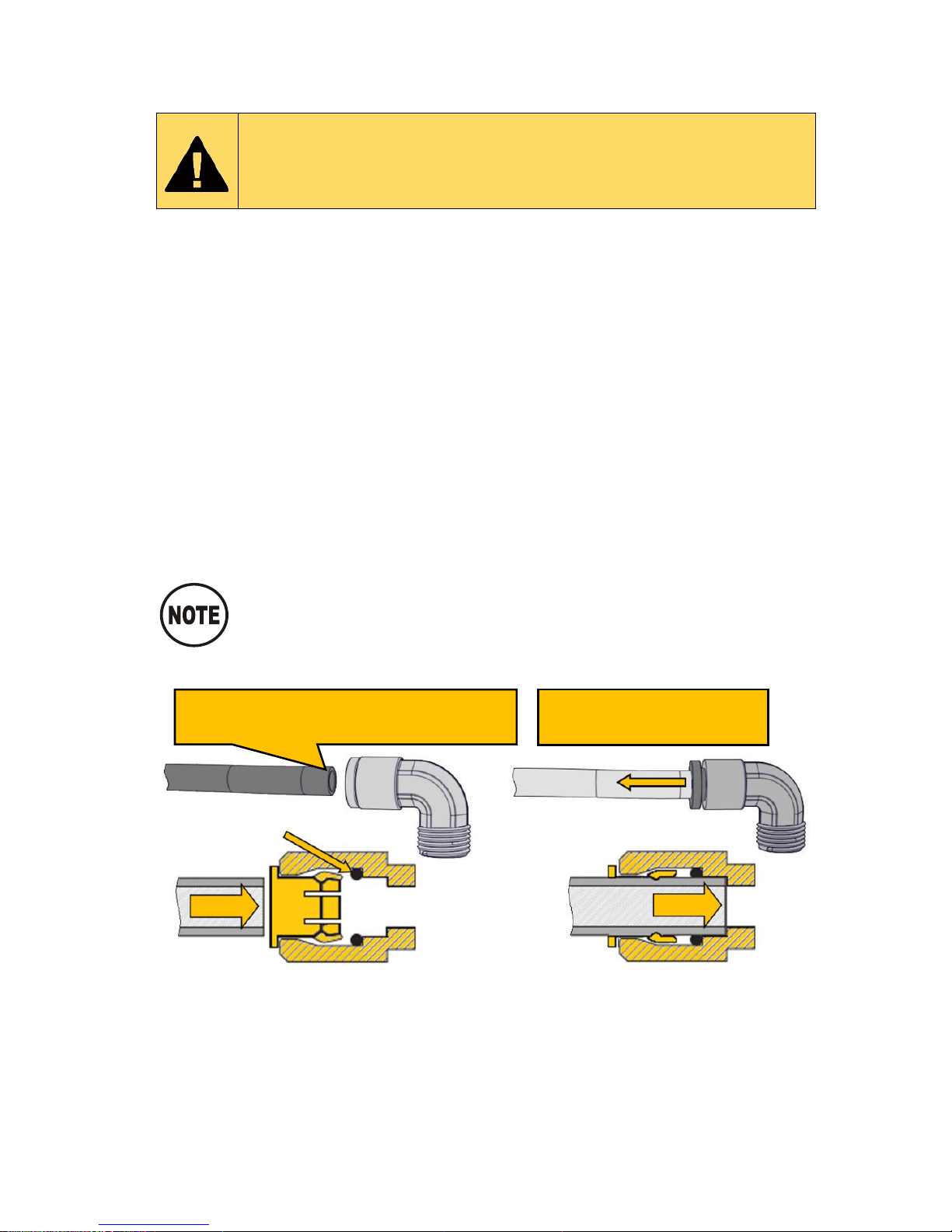
To properly insert the PTFE into the push-to-connect fitting, lubricate the
tube, push it firmly into the fitting until it has fully seated, then slide the
collet back along the tube to lock it into place,
Ensure the tube does not have any play to prevent the O-ring from
wearing.
Lubricate the tube and firmly push it into the fitting so that the
tube fully seats in the fitting. Slide the collet out, away from
the body of the fitting to lock the tubing in place. Ensure the
tube does not have any ‘play’ to prevent the O-ring from
wearing.
Figure 34 – Push-to-connect fittings
Slide the collet out once
the tube is fully inserted
Cut the tube square. Do not use side
cutters as they will deform the tube
O-ring
Page 50
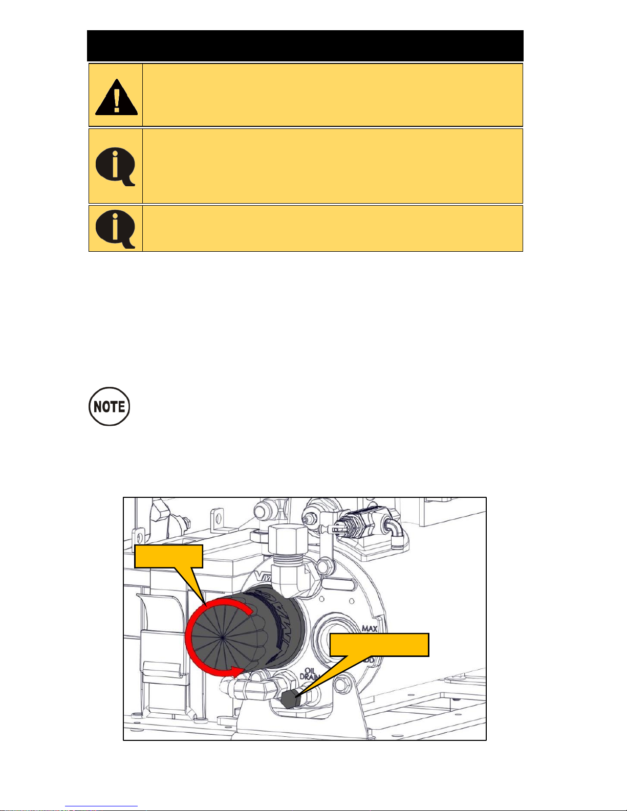
VMAC – Vehicle Mounted Air Compressors
VMAC Technical Support: 1-888-241-2289
VMAC Knowledge Base: www.kb.vmacair.com
48
200 Hour / 6 Month Service
Read the “Maintenance and Repair Safety” section prior to
performing any work on the system (beginning on Page 38).
Wear appropriate Personal Protective Equipment and follow
all industry standard safety practices.
Do not use compressed air or perform any other tasks
around the air filter and cover until both are replaced. Never
clean the filter element with compressed air as this may
allow contaminates to enter the compressor system. Always
replace the air filter element during this service.
Do not overfill the system. Overfilling the system with oil can
flood the sight glass window and make the system appear
empty.
Inspect the blowdown muffler (Page 43).
Inspect the pressure relief valve (Page 44).
Replace the air filter (Page 45).
Inspect the drive belt (Page 46).
Clean the area around the WHASP Tank and the oil filter to prevent
contamination.
Remove the oil drain plug and drain the oil into a container with a
capacity of at least 4 L (1 USG) (Figure 35).
Dependant upon the mounting location of the Gas Engine
Driven 30 CFM Air Compressor, the Remote Oil Drain Kit (P/N:
A500043) may help facilitate draining the compressor oil.
Inspect the Viton O-ring on the oil drain plug for damage, hardness or
defects and replace if necessary.
Install and tighten the oil drain plug.
Remove the oil filter (Figure 35).
Figure 35 – Compressor oil filter
Oil drain plug
Oil filter
Page 51
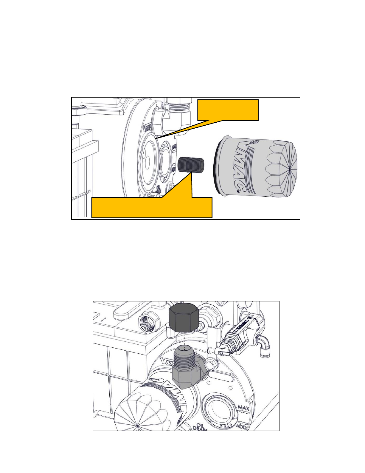
VMAC – Vehicle Mounted Air Compressors
VMAC Technical Support: 1-888-241-2289
VMAC Knowledge Base: www.kb.vmacair.com
49
Ensure the threaded nipple did not unscrew with the oil filter. If the nipple
came out with the oil filter, remove it from the filter carefully to avoid
damaging the threads.
To reinstall the nipple, thoroughly clean the threads and apply
Loctite 242 (blue) to the end with the short threads and replace it in
the tank (Figure 39).
Clean the gasket sealing surface on the front of the tank and inspect it for
damage. The surface must be free of old gasket material and smooth to
ensure a good seal. (Figure 36).
Figure 36 – Compressor oil filter
Apply a thin coat of compressor oil to the rubber gasket on the oil filter.
Spin the filter onto the threaded nipple until the gasket contacts the
sealing surface on the tank, then tighten the filter an additional 3/4 to 1
turn to seat the gasket.
Remove the filler cap on the WHASP Tank. Fill the WHASP Tank with
VMAC compressor oil until is reaches the “MAX” mark. The air
compressor system holds approximately 4 L (1 USG) of oil (Figure 37).
Figure 37 – Compressor oil fill
Inspect sealing
surface
Oil filter nipple (Insert shorter
threaded end into WHASP Tank)
Page 52

VMAC – Vehicle Mounted Air Compressors
VMAC Technical Support: 1-888-241-2289
VMAC Knowledge Base: www.kb.vmacair.com
50
Check the oil level at the sight glass on the front of the WHASP Tank.
Continue adding oil until the level is correct.
Reinstall the fill cap.
Start the engine and check for oil leaks.
Allow the system to build to pressure (factory setting 150 psi) and for the
engine speed to decrease to base idle.
Turn off the engine.
Once the system has sat for 5 minutes, check the oil level through the
sight glass. The level must be between the “MIN” and “MAX” level
indicators.
Verify there are no oil leaks.
Page 53
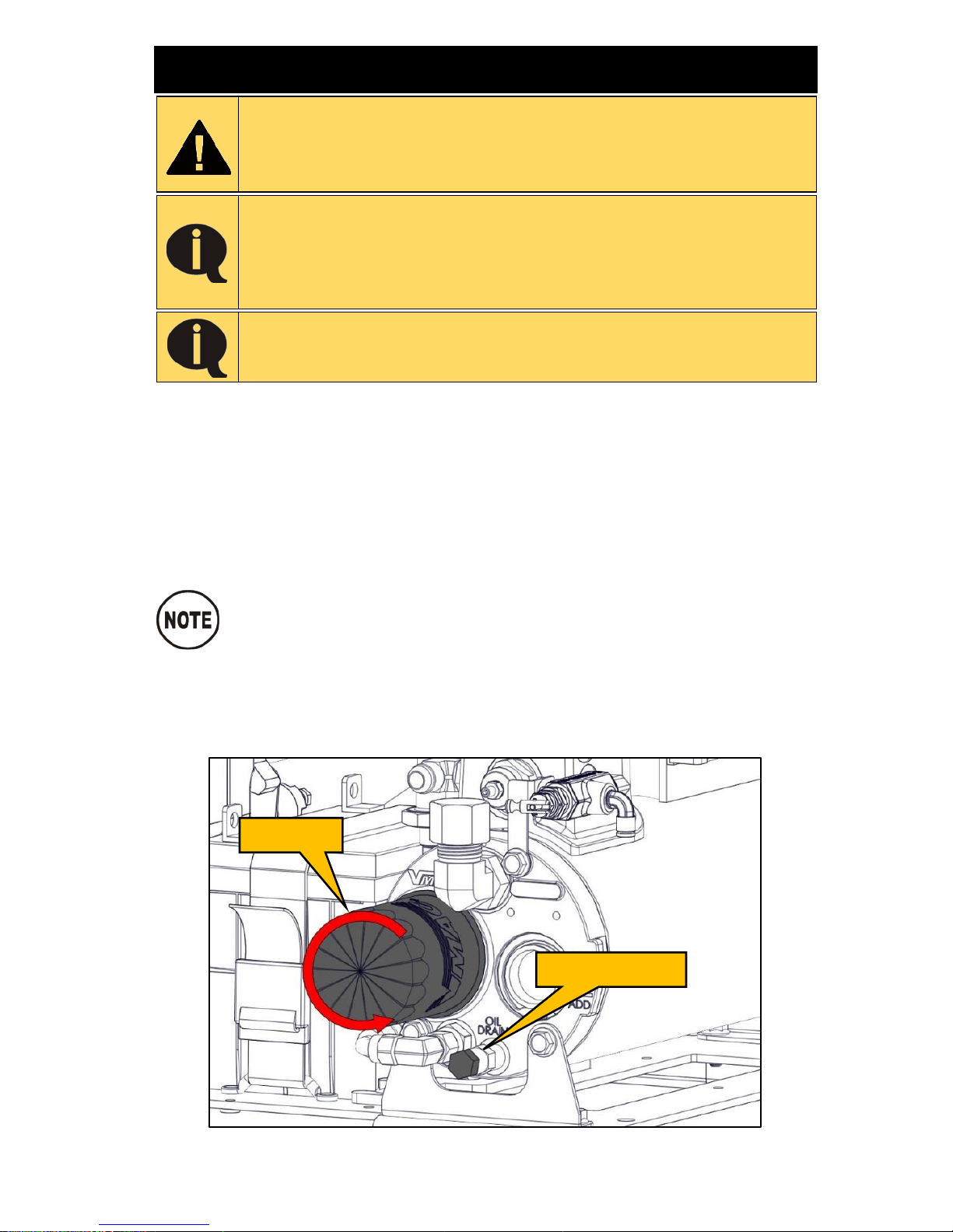
VMAC – Vehicle Mounted Air Compressors
VMAC Technical Support: 1-888-241-2289
VMAC Knowledge Base: www.kb.vmacair.com
51
400 Hour / 1 Year Service
Read the “Maintenance and Repair Safety” section prior to
performing any work on the system (beginning on Page 38 ).
Wear appropriate Personal Protective Equipment and follow
all industry standard safety practices.
Do not use compressed air or perform any other tasks
around the air filter and cover until both are replaced. Never
clean the filter element with compressed air as this may
allow contaminates to enter the compressor system. Always
replace the air filter element during this service.
Do not overfill the system. Overfilling the system with oil can
flood the sight glass window and make the system appear
empty.
Replace the blowdown muffler (Page 43).
Replace the pressure relief valve (Page 44).
Replace the air filter (Page 45).
Inspect the drive belt (Page 46).
Clean the area around the WHASP Tank and the oil filter to prevent
contamination.
Remove the oil drain plug and drain the oil into a container with a
capacity of at least 4 L (1 USG) (Figure 38).
Dependant upon the mounting location of the Gas Engine
Driven 30 CFM Air Compressor, the Remote Oil Drain Kit (P/N:
A500043) may help facilitate draining the compressor oil.
Inspect the Viton O-ring on the oil drain plug for damage, hardness or
defects and replace if necessary.
Install and tighten the oil drain plug.
Remove the oil filter (Figure 38).
Figure 38 – Compressor oil filter
Oil drain plug
Oil filter
Page 54
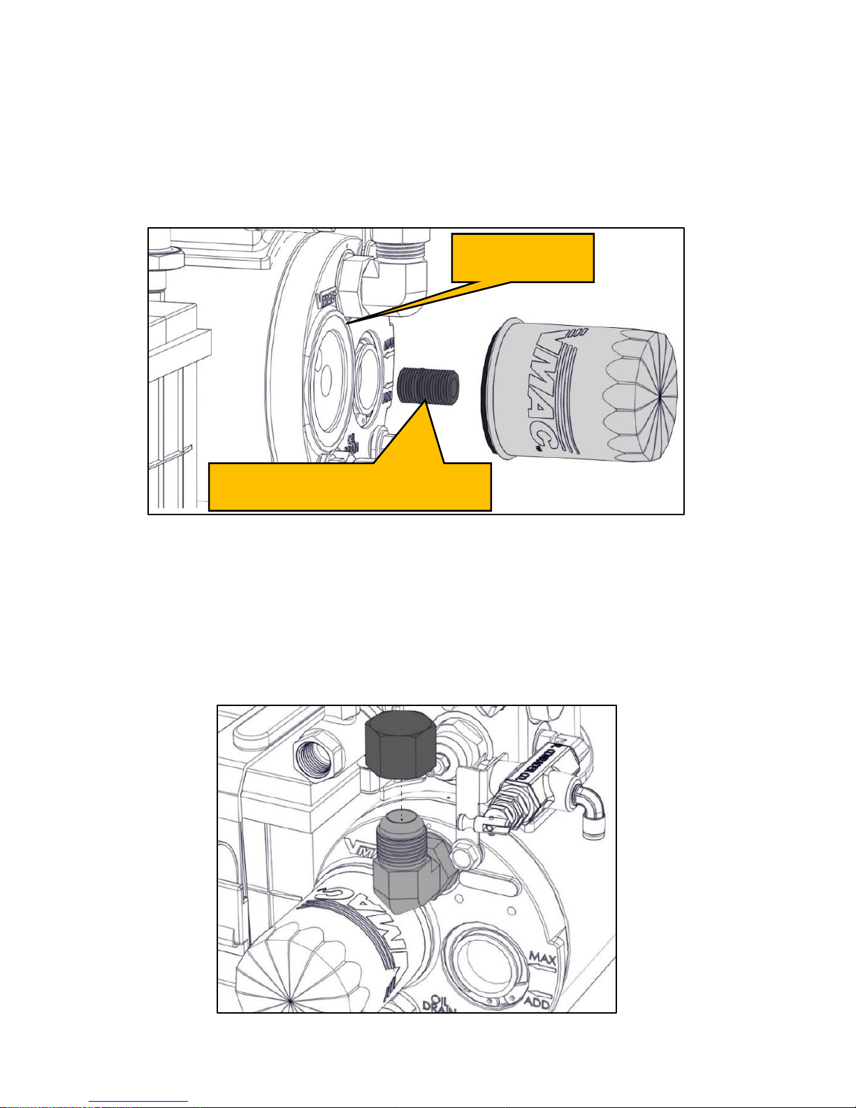
VMAC – Vehicle Mounted Air Compressors
VMAC Technical Support: 1-888-241-2289
VMAC Knowledge Base: www.kb.vmacair.com
52
Ensure the threaded nipple did not unscrew with the oil filter. If the nipple
came out with the oil filter, remove it from the filter carefully to avoid
damaging the threads.
To reinstall the nipple, thoroughly clean the threads and apply
Loctite 242 (blue) to the end with the short threads and replace it in
the tank (Figure 39).
Clean the gasket sealing surface on the front of the tank and inspect it for
damage. The surface must be free of old gasket material and smooth to
ensure a good seal. (Figure 39).
Figure 39 – Compressor oil filter
Apply a thin coat of compressor oil to the rubber gasket on the oil filter.
Spin the filter onto the threaded nipple until the gasket contacts the
sealing surface on the tank, then tighten the filter an additional 3/4 to 1
turn to seat the gasket.
Remove the filler cap on the WHASP Tank. Fill the WHASP Tank with
VMAC compressor oil until is reaches the “MAX” mark. The air
compressor system holds approximately 4 L (1 USG) of oil (Figure 40).
Figure 40 – Compressor oil fill
Inspect sealing
surface
Oil filter nipple (Insert shorter
threaded end into WHASP Tank)
Page 55
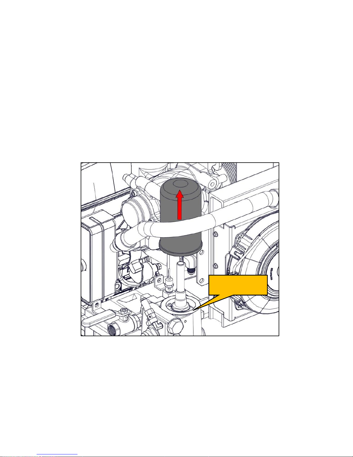
VMAC – Vehicle Mounted Air Compressors
VMAC Technical Support: 1-888-241-2289
VMAC Knowledge Base: www.kb.vmacair.com
53
Check the oil level at the sight glass on the front of the WHASP Tank.
Continue adding oil until the level is correct.
Reinstall the fill cap.
Clean the WHASP Tank around the coalescing filter to prevent
contamination.
Remove the spin on coalescing filter by turning it counterclockwise
(Figure 41).
Clean the gasket sealing surface and inspect it for damage. The surface
must be free of old gasket material and smooth to ensure a good seal
(Figure 41).
Apply a thin coat of compressor oil to the rubber gasket on the new
coalescing filter.
Spin the new filter onto the threaded nipple until the gasket contacts the
sealing surface on the tank, then tighten the filter an additional 3/4 to 1
turn to seat the gasket.
Figure 41 – Coalescing filter
Start the engine and check for oil leaks.
Allow the system to build to pressure (factory setting 150 psi) and for the
engine speed to decrease to base idle.
Turn off the engine.
Once the system has sat for 5 minutes, check the oil level through the
sight glass. The level must be between the “MIN” and “MAX” level
indicators.
Verify there are no oil leaks.
Inspect sealing
surface
Page 56
VMAC – Vehicle Mounted Air Compressors
VMAC Technical Support: 1-888-241-2289
VMAC Knowledge Base: www.kb.vmacair.com
54
Engine Maintenance and Warranty
Information
The VMAC Gas Engine Driven 30 CFM Air Compressor uses the Honda
GX390 engine. For engine service intervals and instructions, refer to the
Honda Owner’s Manual supplied with the system (VMAC P/N: 1901066).
Failure to follow the instructions in the Honda Owner’s Manual could result in
poor engine performance, engine damage and may void the Honda engine
warranty.
For all Honda engine maintenance or warranty questions, contact a local
Honda Power Equipment dealer.
In Canada:
https://powerequipment.honda.ca/where-to-buy
In the United States
http://engines.honda.com/dealer-locator
Page 57
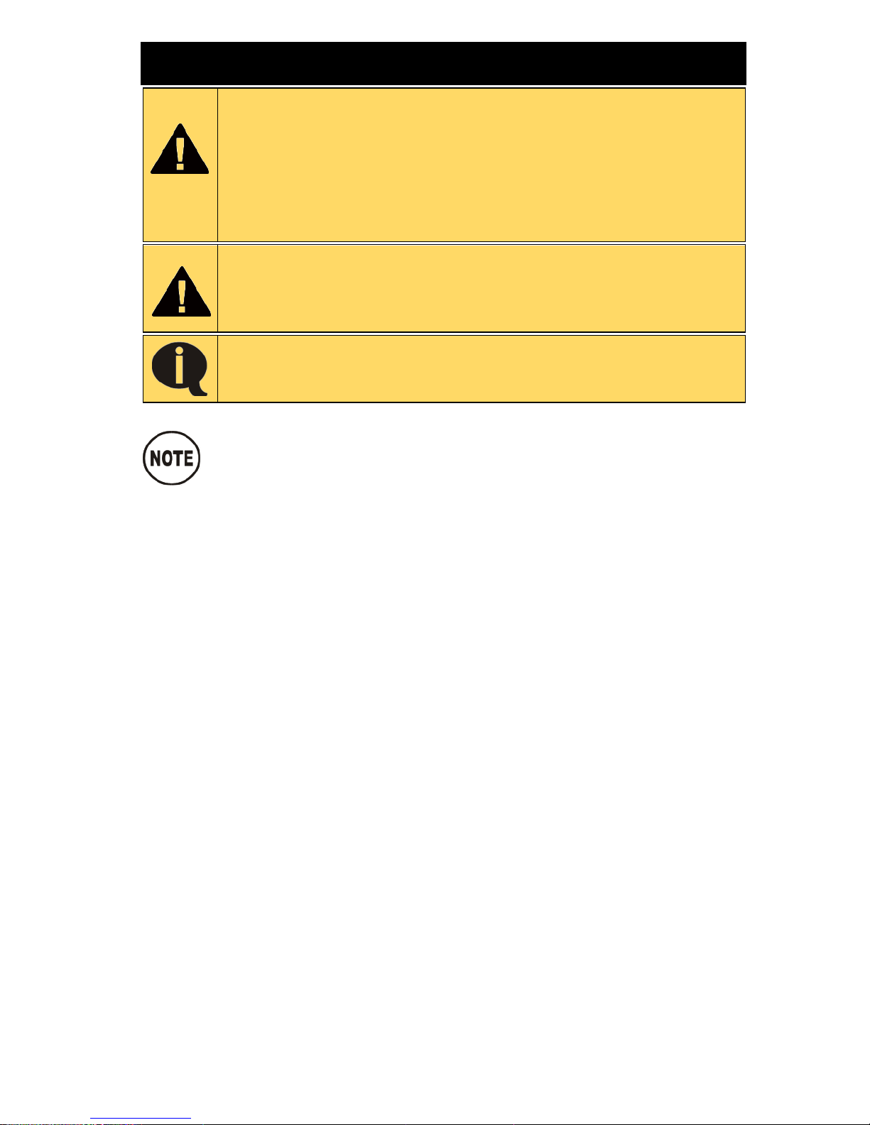
VMAC – Vehicle Mounted Air Compressors
VMAC Technical Support: 1-888-241-2289
VMAC Knowledge Base: www.kb.vmacair.com
55
Diagnostics and Trouble Shooting
This information is intended for people with mechanical
trade certification who have the tools and equipment to
properly and safely perform the service or repair. Do not
attempt to service or repair this system without the
appropriate mechanical training, knowledge and experience.
Follow all safety precautions and industry standard “best
practices”.
Read the “Maintenance and Repair Safety” section prior to
performing any work on the system (beginning on Page 38 ).
Wear appropriate Personal Protective Equipment and follow
all industry standard safety practices.
For the following tests, isolate the Gas Engine Driven 30 CFM
Air Compressor from all downstream (customer supplied)
equipment.
If the Gas Engine Driven 30 CFM Air Compressor is still within
the warranty period, contact VMAC prior to commencing any
diagnostics or repairs.
Problem diagnosis should follow sound, recognized practices. Quick and
accurate diagnosis of problems should involve the following:
• Follow industry standard safety practices.
• Accurately identifying the problem by operating the system.
• Determining the possible causes for the problem by understanding how
the system operates.
• Isolating the potential causes by accurate testing using the correct and
recognized procedures.
• Performing proper repairs using the correct procedures and the
recommended replacement parts.
• Performing proper post repair testing to ensure that the repairs were
effective.
• Electrical testing should be performed according to the processes
described in the troubleshooting charts and in conjunction with any
documentation provided by VMAC.
Page 58
VMAC – Vehicle Mounted Air Compressors
VMAC Technical Support: 1-888-241-2289
VMAC Knowledge Base: www.kb.vmacair.com
56
SYMPTOM
POSSIBLE CAUSE
CORRECTIVE ACTION
Compressor building
above set pressure
(Verified by pressure
gauge) or pressure relief
valve venting at 200 psi.
Pressure control tube
plugged or frozen.
Remove and clear the tube.
Defective inlet or
poppet O-ring.
Replace O-ring.
Defective inlet valve.
Replace inlet assembly.
Plugged or restricted
pressure control tube.
Replace components as needed.
Unloader valve out of
adjustment or failed.
Replace unloader valve.
SYMPTOM
POSSIBLE CAUSE
CORRECTIVE ACTION
Compressor will not build
to set pressure
(Verified by pressure
gauge).
Defective
downstream
equipment (Filter
Regulator Lubricator,
fittings, hose reel.
Replace as required with suitable
components.
Unloader valve
manually activated.
Manually disengage unloader
valve.
Excessive leakage
through blowdown
muffler.
Replace blowdown shuttle valve.
Plugged or dirty
compressor air filter.
Replace air filter.
Drive belt slipping.
Check belt.
Leaks in air lines.
Replace components as needed.
Pressure relief valve
leaking.
Replace pressure relief valve.
Inlet valve regulator
set too low.
Adjust inlet valve regulator.
See p. 68.
SYMPTOM
POSSIBLE CAUSE
CORRECTIVE ACTION
Engine Stalls.
Low fuel in engine.
Add fuel to engine.
Compressor pressure
set too high.
Lower compressor air pressure to
approx. 150 psi.
Ensure unloader activates (rpm
decreases).
Starting compressor
under pressure.
Ensure system is depressurizing
on shut down.
Operating at too high
of an elevation.
See section on elevation on p. 14.
Low engine oil.
Add oil to engine.
Spark plug gap.
Replace spark plug.
Spark arrester
clogged.
Clean or replace the spark
arrester.
Mounted in enclosure.
See enclosure mounting
parameters on p. 21.
Page 59
VMAC – Vehicle Mounted Air Compressors
VMAC Technical Support: 1-888-241-2289
VMAC Knowledge Base: www.kb.vmacair.com
57
SYMPTOM
POSSIBLE CAUSE
CORRECTIVE ACTION
Excessive vibration.
Loose fasteners.
Torque fasteners, use appropriate
thread locking compound.
Belt or pulley worn.
Replace components as needed.
SYMPTOM
POSSIBLE CAUSE
CORRECTIVE ACTION
Excessive oil in the air.
Clogged scavenge tube
or fitting.
Clean or replace.
Coalescing separator
failure.
Replace coalescing filter.
Compressor oil overfilled.
Check oil level with equipment on
level ground.
Operating angle more
than 15° from horizontal.
Reduce operating angle.
Incorrect start up / shut
down procedures.
Observe start up / shut down
procedures detailed in this
manual. SYMPTOM
POSSIBLE CAUSE
CORRECTIVE ACTION
Compressor overheat.
Low compressor oil level.
Check oil level with equipment on
level ground.
Wrong compressor oil
used.
Flush and replace with VMAC
approved compressor oil.
Oil condition.
Service compressor.
Plugged compressor oil
filter.
Replace oil filter.
WHASP Cooler not
functioning or plugged.
Clean or replace the WHASP
Tank
WHASP Cooling fan not
functioning.
Repair or replace.
High ambient
temperatures.
Reduce duty cycle.
Oil temperature switch
failure.
Replace if defective.
Restricted oil lines.
Check for kinked or pinched
lines.
Mounted in enclosure.
See enclosure mounting
parameters on p. 21.
SYMPTOM
POSSIBLE CAUSE
CORRECTIVE ACTION
Engine will not crank.
Battery discharged.
Charge or replace battery.
Use recoil pull start.
Fuel shut off lever left on
during transport, fuel
flooded crank case and
cylinder.
Remove spark plug. Use recoil
starter to drain cylinder. Change
oil and filter.
Page 60
VMAC – Vehicle Mounted Air Compressors
VMAC Technical Support: 1-888-241-2289
VMAC Knowledge Base: www.kb.vmacair.com
58
SYMPTOM
POSSIBLE CAUSE
CORRECTIVE ACTION
Engine rpm does not
decrease.
Throttle tube frozen,
plugged or obstructed.
Clean or replace tube.
Throttle actuator failure.
Replace actuator.
Discharge valve failure.
Replace discharge valve.
Using large receiver tank.
See p. 68.
Inlet regulator pressure
set below unloader valve
pressure setting.
Follow the inlet regulator
adjusting steps on p. 68.
SYMPTOM
POSSIBLE CAUSE
CORRECTIVE ACTION
Engine rpm does not
increase.
Unloader valve manually
activated.
Manually disengage unloader
valve.
Inlet valve regulator
pressure set too low.
Adjust inlet valve regulator to
increase pressure.
Discharge valve failure.
Replace discharge valve. .
Throttle actuator failure.
Replace actuator.
SYMPTOM
POSSIBLE CAUSE
CORRECTIVE ACTION
Blowdown does not
function.
Scavenge tube frozen,
plugged or obstructed.
Clean or replace tube.
Blowdown muffler
plugged or obstructed.
Replace muffler.
Blowdown valve failure.
Replace blowdown valve
assembly.
SYMPTOM
POSSIBLE CAUSE
CORRECTIVE ACTION
Oil comes out of the
blowdown muffler.
Operating angle more
than 15° from horizontal.
Reduce operating angle.
Compressor oil overfilled.
Check oil level with equipment on
level ground.
Faulty blowdown shuttle
valve.
Replace blowdown shuttle valve.
Blowdown valve failure.
Replace blowdown valve
assembly.
SYMPTOM
POSSIBLE CAUSE
CORRECTIVE ACTION
Engine overheat.
High ambient
temperatures.
Reduce duty cycle.
Low engine oil level.
Check engine oil level with
equipment on level ground.
Cooling intake plugged.
Correct problem.
Insufficient ventilation.
Correct problem.
Spark arrester fouled.
Clean spark arrester.
Mounted in enclosure.
See enclosure mounting
parameters on p. 21.
Page 61
VMAC – Vehicle Mounted Air Compressors
VMAC Technical Support: 1-888-241-2289
VMAC Knowledge Base: www.kb.vmacair.com
59
SYMPTOM
POSSIBLE CAUSE
CORRECTIVE ACTION
Engine will not start.
Fuel lever off.
Turn fuel lever on.
Starting with pressure in
the compressor.
Check blowdown function.
Compressor temperature
too high.
Diagnose and repair.
Compressor temperature
switch faulty.
Replace switch.
Low engine oil.
Add oil to engine.
Low fuel in engine.
Add fuel to engine.
Spark plug gap.
Replace spark plug.
Engine air intake
restricted.
Remove restriction / replace air
filter.
Engine exhaust system
plugged or restricted.
Clean or replace exhaust / spark
arrester.
Fuel bowl / filter plugged
or restricted.
Clean or replace.
Battery discharged.
Charge or replace battery.
Starter failure.
Replace starter or use recoil pull
start.
SYMPTOM
POSSIBLE CAUSE
CORRECTIVE ACTION
Pressure relief valve
venting below 200 psi.
Defective pressure relief
valve.
Replace pressure relief valve.
SYMPTOM
POSSIBLE CAUSE
CORRECTIVE ACTION
Air leaking from small
hole in inlet valve
regulator cap.
This is normal and as per
design.
None required.
Table 5 – Trouble shooting table
Page 62
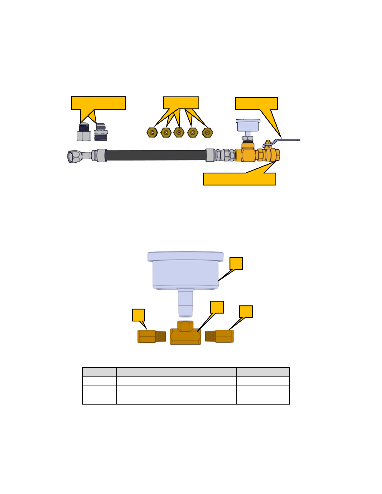
VMAC – Vehicle Mounted Air Compressors
VMAC Technical Support: 1-888-241-2289
VMAC Knowledge Base: www.kb.vmacair.com
60
Diagnostic Tools
VMAC Air Test Tool (P/N: A700052)
To properly diagnose VMAC’s Gas Engine Driven 30 CFM Air Compressor, a
VMAC Air Test Tool (P/N: A700052), or equivalent, is required.
For testing and diagnosis, install the 30 cfm (1/8 in) orifice.
Figure 42 – A700052 VMAC Air Test Tool
PTFE Test Tool
A PTFE test tool can be constructed and used to test the unloader valve and
throttle actuator function (Figure 43, Table 6).
Figure 43 – PTFE Test Tool
Item
Description
Quantity 1 200 psi Gauge
1
2
T-fitting
1
3
1/4 in Push-to-connect fittings
2
Table 6 – PTFE Test Tool
1
3
3
2
JIC adaptors
Orifices
Ball valve
Install orifice here
Page 63
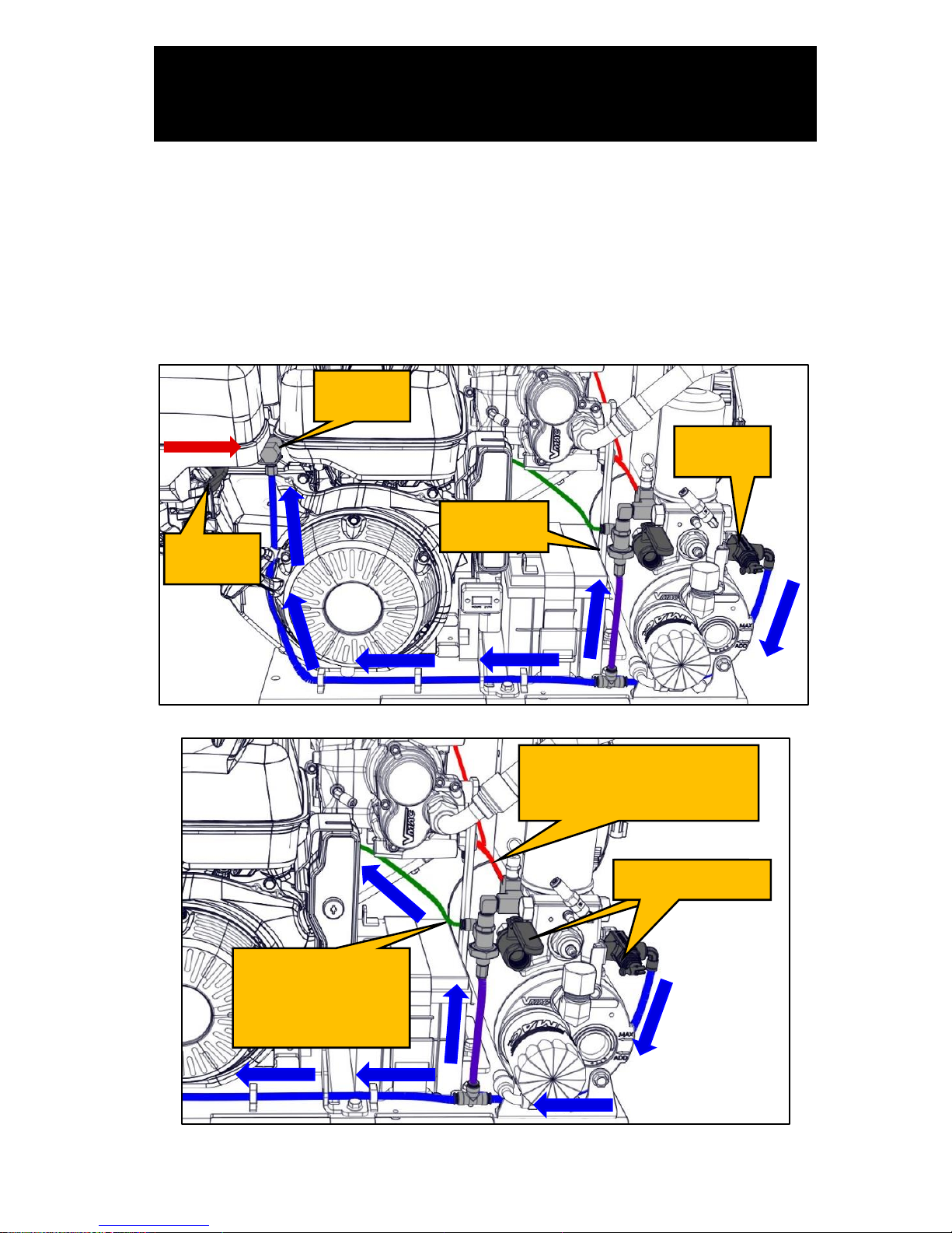
VMAC – Vehicle Mounted Air Compressors
VMAC Technical Support: 1-888-241-2289
VMAC Knowledge Base: www.kb.vmacair.com
61
Compressor Regulation and Throttle
Actuator Testing
Throttle Control
VMAC configures the Honda engine throttle to be wide open in its neutral
state (0 psi). Engine rpm is controlled via the throttle actuator which is
operated by air pressure from the unloader valve.
Once air pressure at the ball valve and unloader valve (“downstream
pressure”) reaches 150 psi, the throttle actuator closes the throttle, reducing
engine speed to idle. “Downstream pressure” opens the discharge valve
diaphragm, via the 1/4 in PTFE tube, and allows air pressure to close the inlet
valve poppet (Figure 44, Figure 45, Figure 46).
Figure 44 – Throttle operation
Figure 45 – Throttle operation
Steady system pressure
to inlet regulator
(0-150 psi)
Tool pressure
System pressure
once discharge
valve diaphragm
opens at 150 psi
Throttle
lever
Throttle
actuator
Unloader
valve
Discharge
valve
Page 64
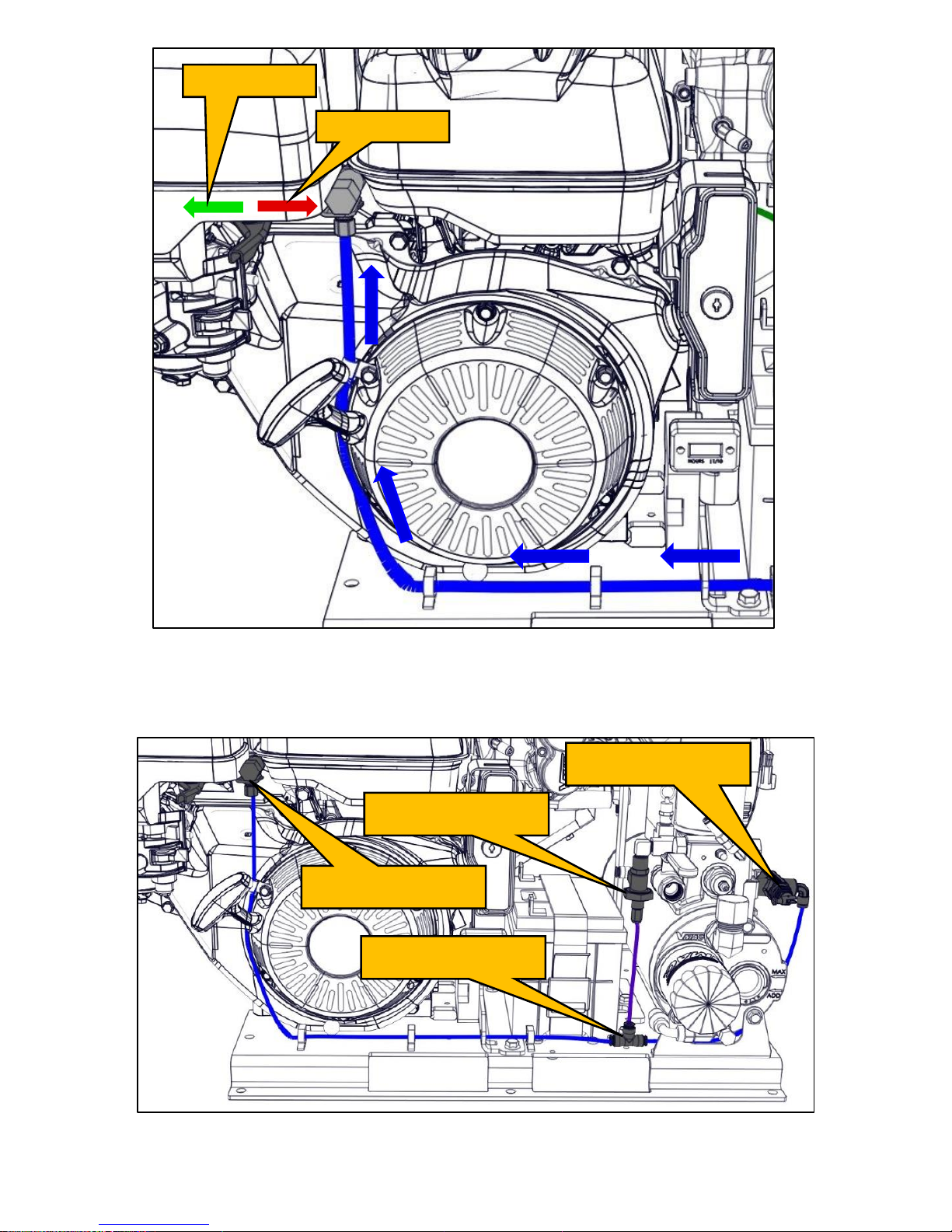
VMAC – Vehicle Mounted Air Compressors
VMAC Technical Support: 1-888-241-2289
VMAC Knowledge Base: www.kb.vmacair.com
62
Figure 46 – Throttle actuator
Throttle Tube
A 1/4 in PTFE tube (shown in “blue”) connects the discharge valve and
unloader valve to the throttle actuator via a 1/4 in PTFE union (Figure 47).
Figure 47 – Throttle actuator tube
Open throttle
Close throttle
Throttle actuator
1/4 in PTFE union
Discharge valve
Unloader valve
Page 65
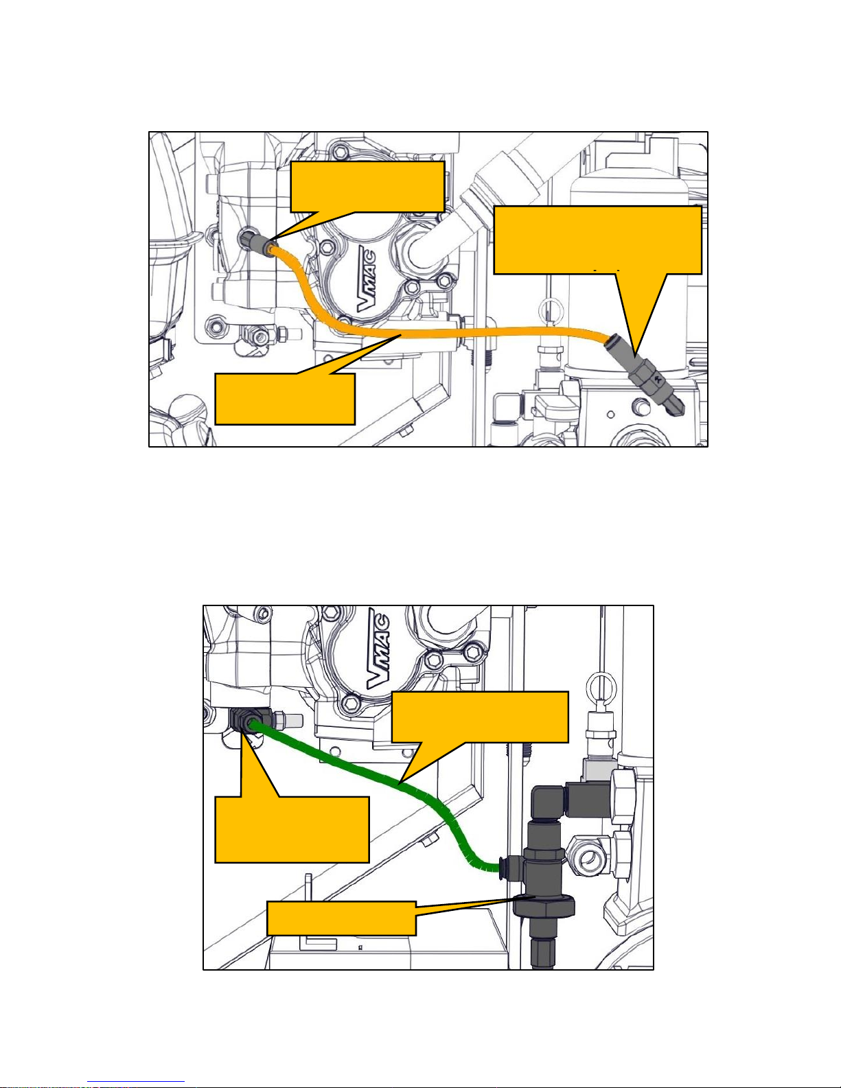
VMAC – Vehicle Mounted Air Compressors
VMAC Technical Support: 1-888-241-2289
VMAC Knowledge Base: www.kb.vmacair.com
63
Scavenge Tube
A 1/4 in PTFE tube (shown in orange) connects the WHASP Tank to the
compressor inlet valve. Vacuum from the compressor pulls the separated oil
from the coalescing filter, recirculating the oil in the system (Figure 48).
Figure 48 – Scavenge tube
(Key switch module removed for clarity)
Pressure Control Tubes
A 1/4 in PTFE tube (shown in green) connects the discharge valve to the
lower fitting on the side of the compressor inlet valve. This provides the
system air pressure (factory setting 150 psi) to operate the inlet poppet valve
(Figure 49).
Figure 49 – 1/4 in Pressure control tube
(Key switch module removed for clarity)
1/4 in compressor
fitting and air
bleed muffler
Discharge valve
1/4 in PTFE pressure
control tube
1/4 in WHASP Tank
scavenge fitting
(with one-way check
1/4 in PTFE
scavenge tube
1/4 in compressor
scavenge fitting
Page 66
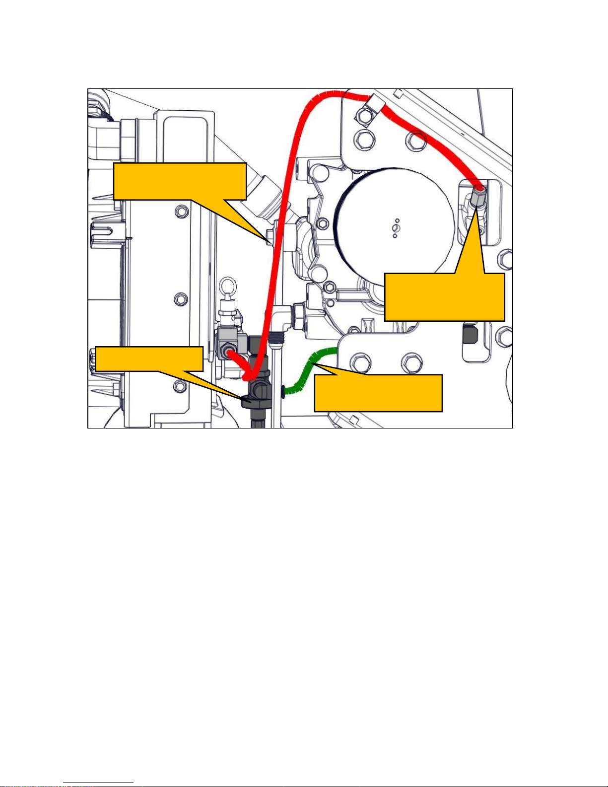
VMAC – Vehicle Mounted Air Compressors
VMAC Technical Support: 1-888-241-2289
VMAC Knowledge Base: www.kb.vmacair.com
64
A 3/16 in PTFE tube (shown in red) connects the discharge valve to the
topmost fitting on the side of the compressor inlet valve. This provides the
system air pressure (factory setting 150 psi) to operate the inlet valve
regulator which works in tandem with the discharge valve (Figure 50).
Figure 50 – 3/16 in Pressure control tube
(Belt guard removed for clarity)
Discharge valve
1/4 in PTFE pressure
control tube
3/16 in PTFE pressure
control tube
3/16 in compressor
fitting at inlet
regulator
Page 67
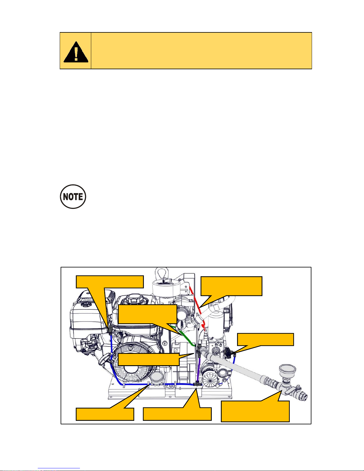
VMAC – Vehicle Mounted Air Compressors
VMAC Technical Support: 1-888-241-2289
VMAC Knowledge Base: www.kb.vmacair.com
65
Throttle Control Testing
Read the “Maintenance and Repair Safety” section prior to
performing any work on the system (beginning on Page 38 ).
Wear appropriate Personal Protective Equipment and follow
all industry standard safety practices.
The air pressure (inlet valve) and engine rpm (throttle actuator) are controlled
by the unloader valve. As air pressure from the unloader valve increases, it
forces the throttle actuator to reduce engine rpm. Once the system has built
to full system pressure (150 psi) the force from the unloader valve will move
the throttle to base idle.
While the system is building air pressure, the PTFE test tool gauge will
indicate 0 psi and the throttle will be wide open. Once downstream pressure
reaches 150 psi it will actuate the unloader valve which opens the discharge
valve. The PTFE test tool gauge will indicate 150 psi and air pressure from
the discharge valve will force the throttle closed. When downstream pressure
drops below 120 psi the discharge valve will close (the PTFE test tool gauge
will indicate 0 psi) and allow the throttle to return to its neutral state of wide
open.
The following testing is for systems set at factory pressure
(150 psi).
With the system off and depressurized:
Remove the WHASP Tank shroud.
Remove the ball valve fitting to accommodate the test tool.
Install a test tool on the system outlet (Figure 51).
Install the PTFE test tool (Figure 43 and Table 6 on page 60) on the 1/4
in throttle tube (Figure 51).
Figure 51 – Test equipment installed
(Scavenge tube not shown)
Throttle actuator
PTFE Test Tool
1/4 in PTFE union
VMAC Air Test
Tool (A700052)
Unloader valve
Discharge valve
1/4 in pressure
control tube
3/16 in pressure
control tube
Page 68
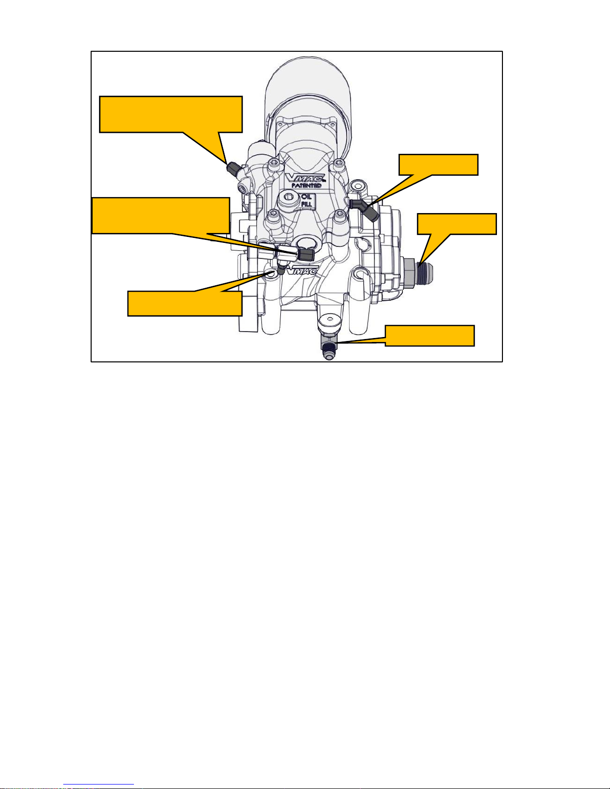
VMAC – Vehicle Mounted Air Compressors
VMAC Technical Support: 1-888-241-2289
VMAC Knowledge Base: www.kb.vmacair.com
66
Compressor Connections
Figure 52 – Compressor connections
Start the engine, and monitor both pressure gauges:
1) As the pressure indicated on the VMAC test tool gauge reaches 150 psi,
the gauge connected to the 1/4 in PTFE tube should indicate 150 psi. If
the pressure on the gauge connected to the 1/4 in PTFE tube does not
increase, confirm the manual unloader valve has not been adjusted. If the
unloader valve has not been adjusted the discharge valve needs to be
replaced.
2) As the pressure indicated on the PTFE Test Tool gauge connected to the
1/4 in PTFE tube reaches 150 psi, the throttle actuator rod should move
to the right and the engine rpm should decrease. If the throttle actuator
rod does not move, diagnose or replace the throttle actuator.
3) When the system pressure indicated on the VMAC test tool reaches 150
psi, the pressure indicated on the gauge connected to the 1/4 in PTFE
should hold steady at 150 psi. If the pressure does not hold, check for air
leaks or a defective throttle actuator.
4) Slowly open the test tool ball valve. The pressure on both gauges should
drop at approximately the same rate until pressure at the discharge valve
reaches 120 psi. Once the discharge valve pressure drops to 120 psi, the
discharge valve will close and the PTFE test tool gauge will indicate 0 psi.
If the pressures do not drop at the same rate, the discharge valve may be
plugged.
Oil return
Discharge
Scavenge
Throttle (3/16 in
pressure control tube)
Throttle (1/4 in
pressure control tube)
Air bleed muffler
Page 69
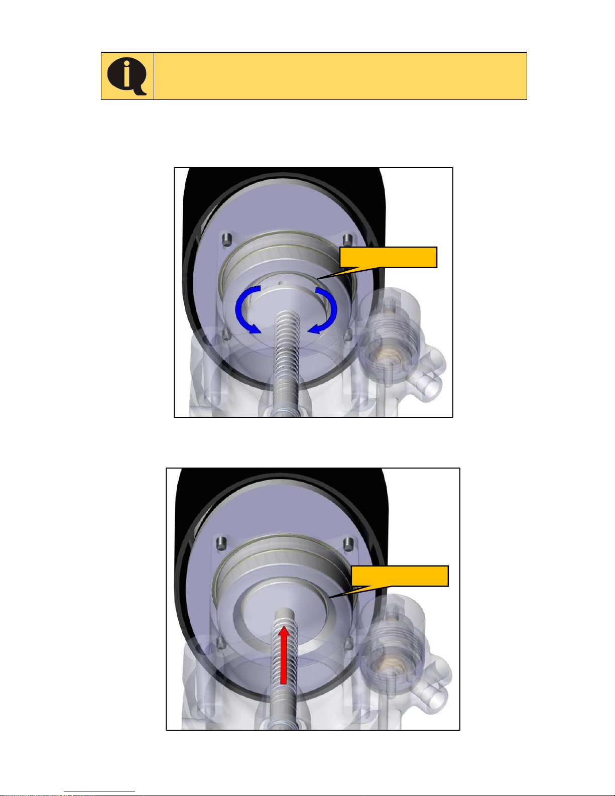
VMAC – Vehicle Mounted Air Compressors
VMAC Technical Support: 1-888-241-2289
VMAC Knowledge Base: www.kb.vmacair.com
67
Poppet Valve
If the inlet or poppet O-ring is damaged or missing, the
compressor may over pressurize and may cause a
compressor oil leak.
Air pressure generated by the compressor is controlled mechanically via the
inlet valve poppet.
When the inlet valve poppet is open, the compressor will build air pressure
(Figure 53).
Figure 53 – Inlet valve poppet open
When the inlet valve poppet is closed, the compressor will not build air
pressure (Figure 54).
Figure 54 – Inlet valve poppet closed
Poppet O-ring
Poppet O-ring
Page 70
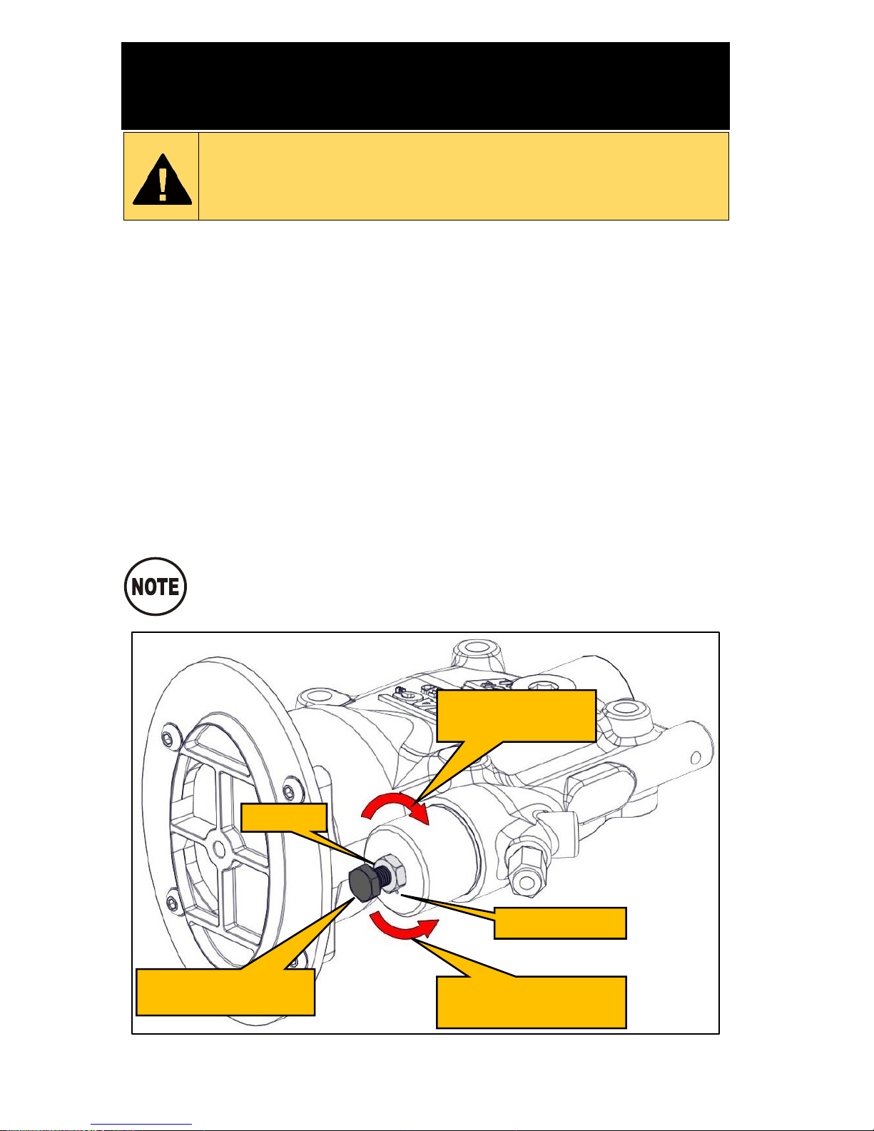
VMAC – Vehicle Mounted Air Compressors
VMAC Technical Support: 1-888-241-2289
VMAC Knowledge Base: www.kb.vmacair.com
68
System Adjustment for Large
Receiver Tanks
Read the “Maintenance and Repair Safety” section prior to
performing any work on the system (beginning on Page 38).
Wear appropriate Personal Protective Equipment and follow
all industry standard safety practices.
When air receiver tanks with a capacity of 25 USG or more are used with the
Gas Engine Driven 30 CFM Air Compressor, some users may find that the
system does not activate the discharge valve and the engine speed will not
decrease once system pressure (150 psi) is reached. This is due to the
interrelation between the unloader valve, discharge valve and the regulated
inlet valve.
A quick test to confirm this is to lightly tap the discharge valve after the
system pressure reaches 150 psi. If the discharge valve vents and the engine
rpm decreases, the inlet valve regulator will need to be adjusted.
Adjusting the Inlet regulator
Loosen the locknut.
Rotate the pressure adjusting bolt clockwise 1/8 of a rotation.
Tighten the locknut.
Test the system.
If required, repeat these steps, rotating the adjusting bolt no
more than 1/8 of a rotation at a time until the system unloads
and reduces engine speed.
Figure 55 – Adjusting the inlet valve regulator
Clockwise to
increase pressure
Counterclockwise to
decrease pressure
Locknut
Pressure adjusting
bolt
Air bleed hole
Page 71
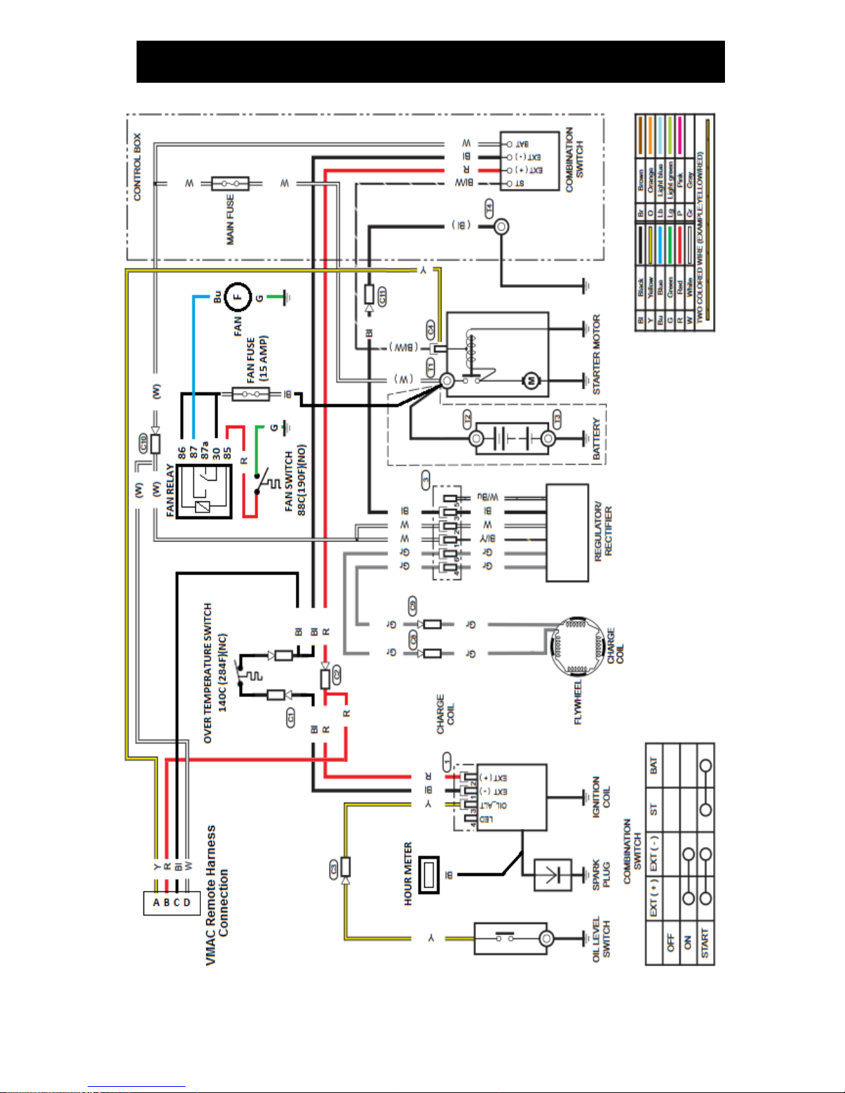
VMAC – Vehicle Mounted Air Compressors
VMAC Technical Support: 1-888-241-2289
VMAC Knowledge Base: www.kb.vmacair.com
69
Electrical Components and Testing
Figure 56 – VMAC electrical harness schematic
Page 72
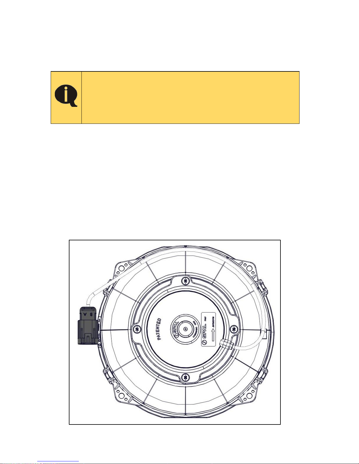
VMAC – Vehicle Mounted Air Compressors
VMAC Technical Support: 1-888-241-2289
VMAC Knowledge Base: www.kb.vmacair.com
70
Electrical components
• Overtemperature switch
• Key switch
• Fan switch
• Hour meter
• Electric fan
• Starter
Fuses
A 15 A fuse protects the OEM electrical system and a
separate 15 A fuse protects the WHASP cooling fan. If the
fuse blows repeatedly, there is an electrical problem that
must be resolved.
Installation of a higher amperage fuse may damage
components and will void the warranty.
A 15 A fuse protects the Gas Engine Driven 30 CFM Air Compressor’s fan
electrical system. The fuse holder is located in the wiring harness next to the
battery.
A 15 A fuse protects the OEM electrical system. This fuse is located inside
the OEM ignition key enclosure.
WHASP Cooling Fan
The cooling fan on the WHASP Tank will run any time the WHASP fan
temperature switch detects temperatures above 88 °C (190 °F).
Testing
Use a “jumper” to supply 12 V to pin “A” of the fan plug and a ground to
pin “B” of the plug to confirm the fan runs when power is supplied.
Figure 57 – WHASP Tank cooling fan
Page 73
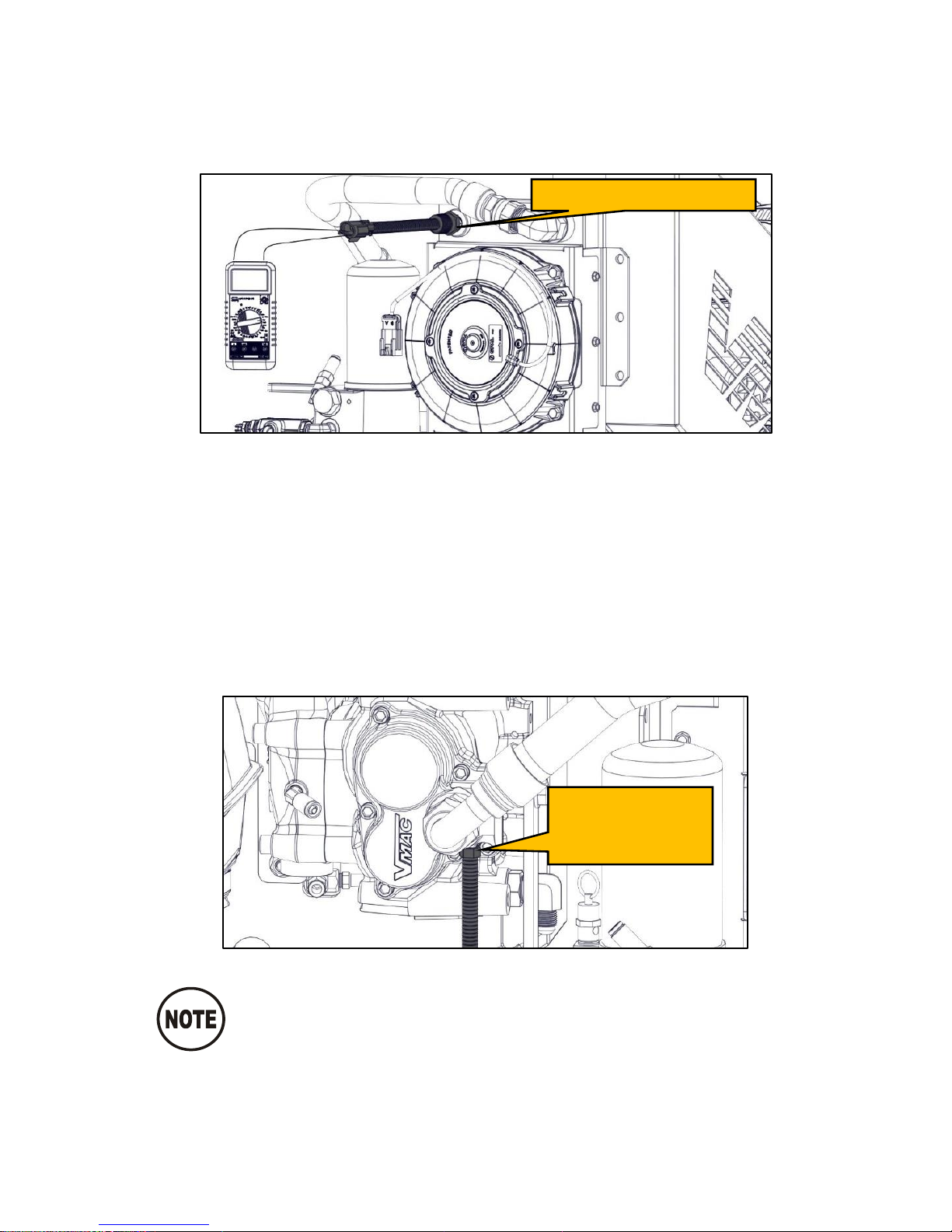
VMAC – Vehicle Mounted Air Compressors
VMAC Technical Support: 1-888-241-2289
VMAC Knowledge Base: www.kb.vmacair.com
71
Fan Temperature Switch
The Gas Engine Driven 30 CFM Air Compressor’s cooling fan temperature
switch is normally open and closes at 88 °C (190 °F) turning on the fan. The
temperature switch is located in the top of the WHASP Tank cooler
(Figure 58).
Figure 58 – Fan temperature switch location
Testing
Connect a multimeter to the harness and direct a heat gun onto the
temperature switch for a few minutes. Once the switch reaches 88 °C
(190 °F), resistance on the switch should drop to 0 Ω.
Compressor Temperature Switch
If the compressor’s oil temperature exceeds 140 °C (284 °F), the thermostatic
switch located in the compressor discharge cap will disable the engine
ignition system. The cooling fan will continue to run until the temperature at
the switch drops below 139 °C (282 °F ) (Figure 59).
Figure 59 – compressor temperature switch location
The engine will not run until the compressor system has
cooled enough that the temperature switch closes.
Testing
Use a multimeter to measure the resistance through the switch. The
resistance should be 0 Ω when the system is cold.
Fan temperature switch
Compressor
temperature
switch
Page 74
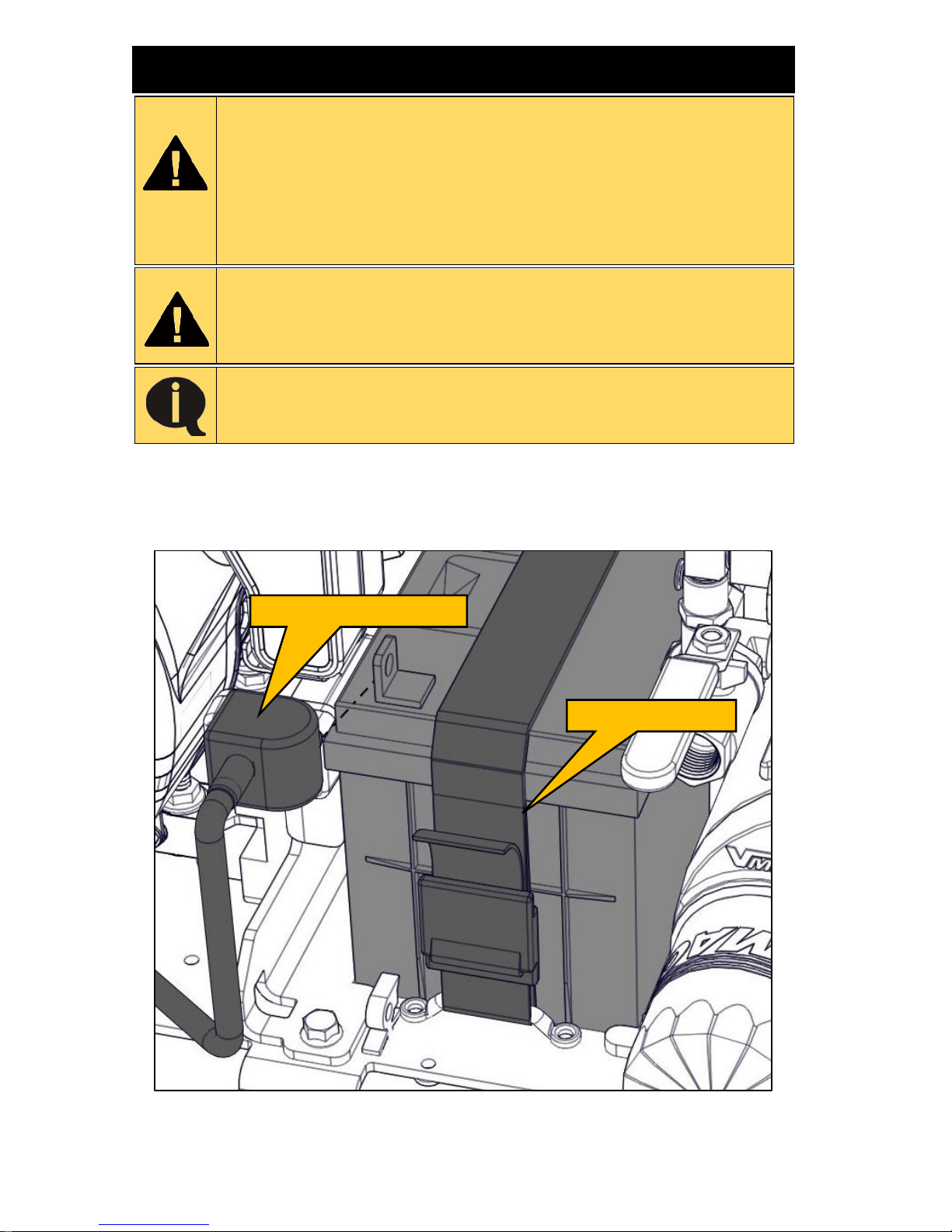
VMAC – Vehicle Mounted Air Compressors
VMAC Technical Support: 1-888-241-2289
VMAC Knowledge Base: www.kb.vmacair.com
72
Component Repair / Replacement
The information in this chapter is intended for people with
mechanical trade certification who have the tools and
equipment to properly and safely perform the service. Do not
attempt this installation without the appropriate mechanical
training, knowledge and experience.
Follow all safety precautions and industry standard “best
practices”.
Read the “Maintenance and Repair Safety” section prior to
performing any work on the system (beginning on Page 38).
Wear appropriate Personal Protective Equipment and follow
all industry standard safety practices.
Use Loctite 242 (blue) on all fasteners unless otherwise
directed.
Battery Replacement
Remove the shroud and disconnect the negative battery cable.
Undo the battery hold down strap (Figure 60).
Figure 60 – Battery hold down
Negative battery cable
Restraining strap
Page 75
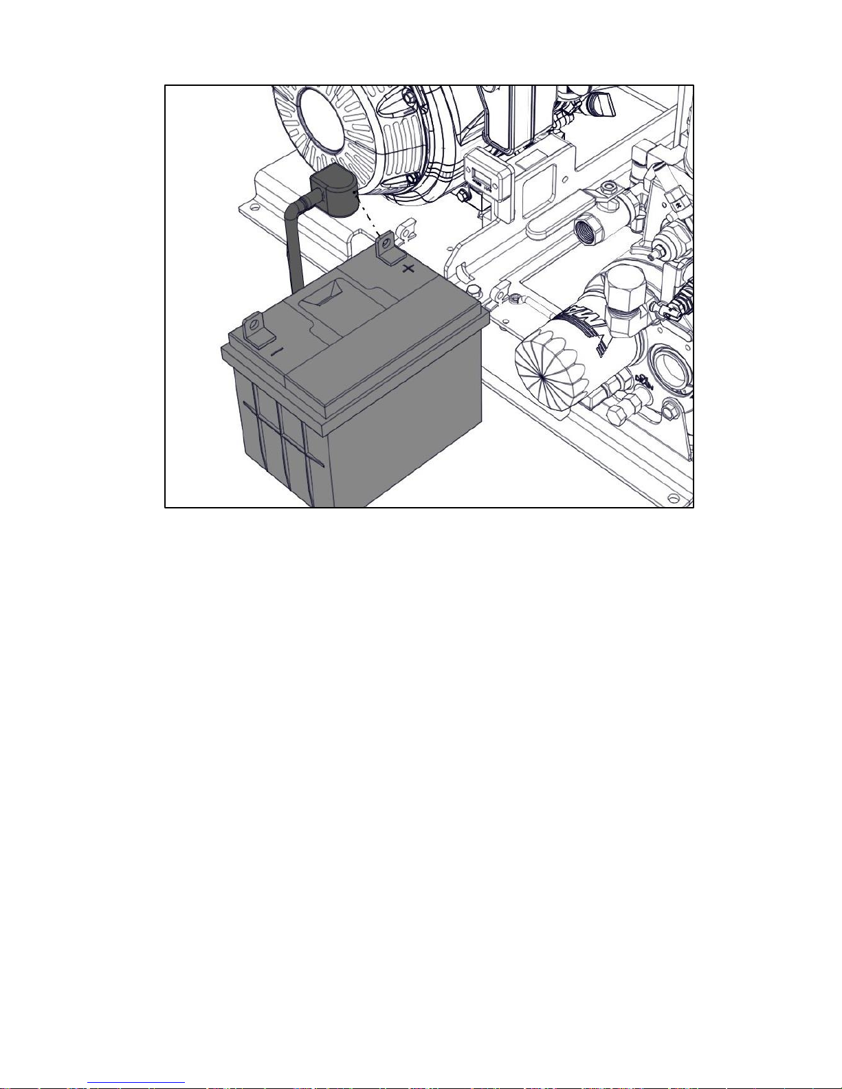
VMAC – Vehicle Mounted Air Compressors
VMAC Technical Support: 1-888-241-2289
VMAC Knowledge Base: www.kb.vmacair.com
73
Pull the battery out of the front of the unit, once it is clear, disconnect the
positive battery terminal (Figure 61).
Figure 61 – Battery removal
Install the battery in the reverse order.
Page 76
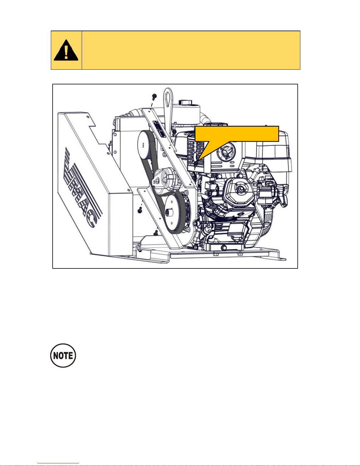
VMAC – Vehicle Mounted Air Compressors
VMAC Technical Support: 1-888-241-2289
VMAC Knowledge Base: www.kb.vmacair.com
74
Compressor Replacement
Read the “Maintenance and Repair Safety” section prior to
performing any work on the system (beginning on Page 38).
Wear appropriate Personal Protective Equipment and follow
all industry standard safety practices.
Remove the 5 fasteners from the belt guard and remove the belt guard.
Figure 62 – Remove belt guard
Using a 3/8 in drive, remove tension from the drive belt.
Remove the belt and set it aside for later.
Disconnect the 3/4 in hose from the rear of the compressor.
Disconnect the 1/2 in hose from the side of the compressor.
Disconnect the 3 PTFE tubes from the compressor.
After disconnecting the hoses and PTFE tubes, plug the ends
to prevent contaminants from entering the system.
Remove fasteners (5x)
Page 77
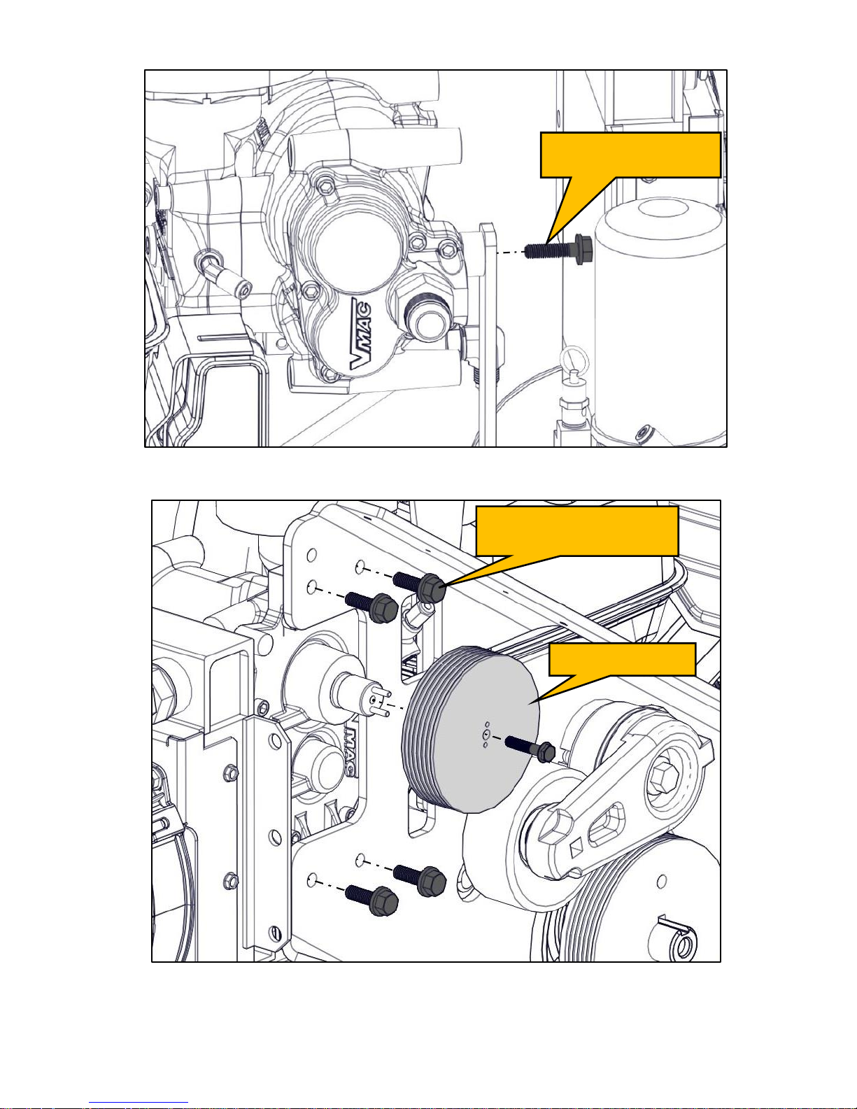
VMAC – Vehicle Mounted Air Compressors
VMAC Technical Support: 1-888-241-2289
VMAC Knowledge Base: www.kb.vmacair.com
75
Remove the bolt from the side of the compressor (Figure 63).
Figure 63 – Remove compressor
Remove the compressor pulley (Figure 64).
Figure 64 – Remove compressor
Remove the 4 bolts securing the compressor to the belt guard
(Figure 64).
Remove compressor
mounting bolt
Remove compressor
mounting bolts (4x)
Remove pulley
Page 78
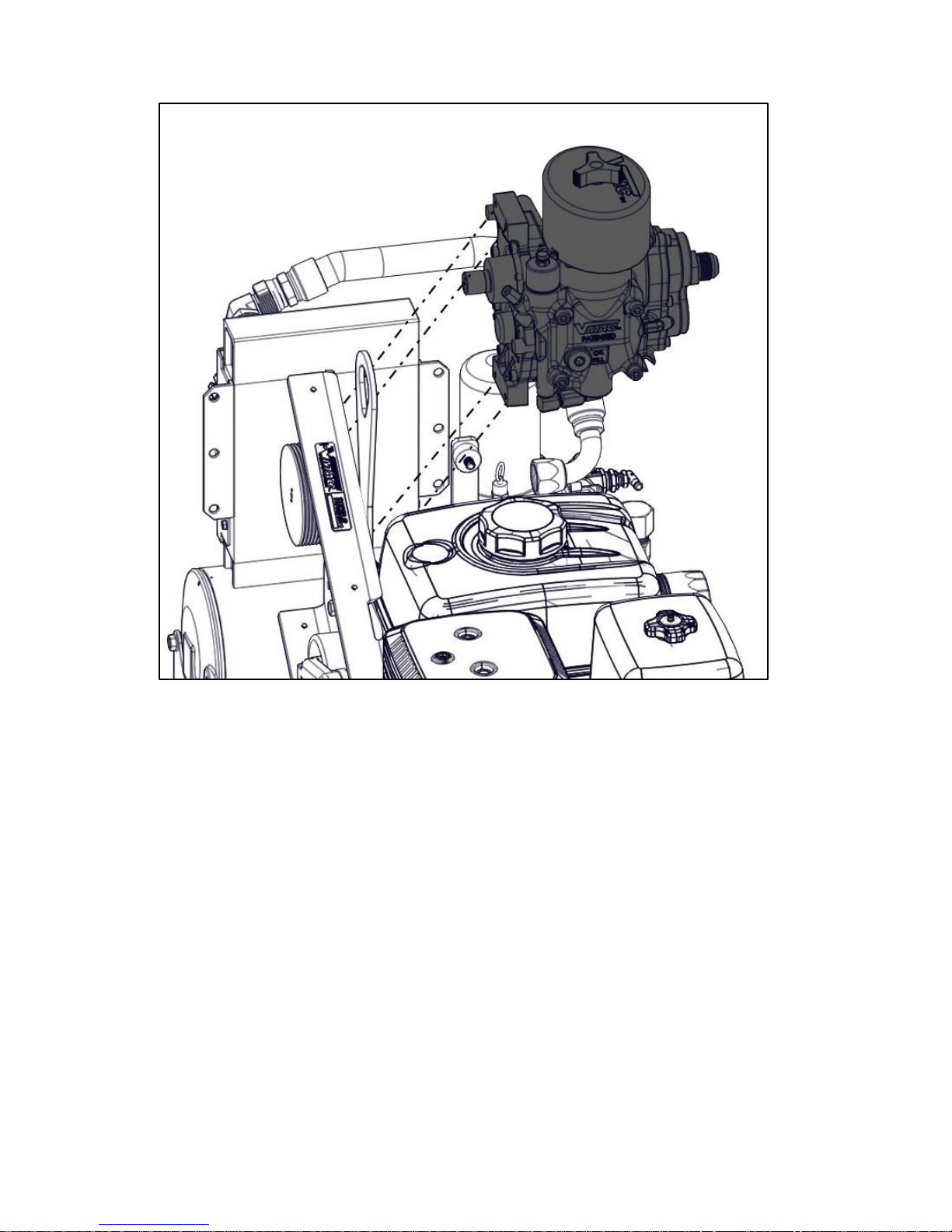
VMAC – Vehicle Mounted Air Compressors
VMAC Technical Support: 1-888-241-2289
VMAC Knowledge Base: www.kb.vmacair.com
76
Lift the compressor up and away from the belt guard to remove it
(Figure 65).
Figure 65 – Remove compressor
Install the compressor in the reverse order.
Page 79
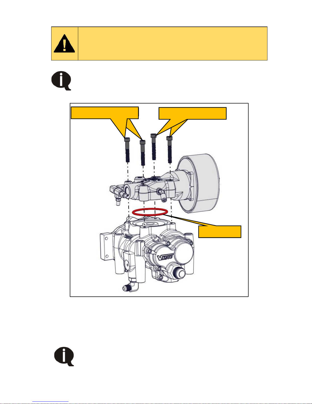
VMAC – Vehicle Mounted Air Compressors
VMAC Technical Support: 1-888-241-2289
VMAC Knowledge Base: www.kb.vmacair.com
77
Inlet Valve Replacement
Read the “Maintenance and Repair Safety” section prior to
performing any work on the system (beginning on Page 38 ).
Wear appropriate Personal Protective Equipment and follow
all industry standard safety practices.
The compressor inlet valve uses 2 different length bolts. The
longer bolts are 55 mm long and the shorter ones are 50 mm
long. Ensure the bolts are installed in the correct position.
Installing the inlet bolts in the wrong location could severely
damage the compressor (Figure 66).
Figure 66 – Inlet valve fasteners
Follow the instructions to remove the compressor (starting on page 74).
Place the compressor on a bench.
Remove the 4 socket head bolts securing the inlet valve to the
compressor.
Ensure the O-ring is not defective or damaged.
Loctite is not required on the inlet valve bolts.
Install the inlet valve in the reverse order.
Longer fasteners (2x)
Shorter fasteners (2x)
Viton O-ring
Page 80
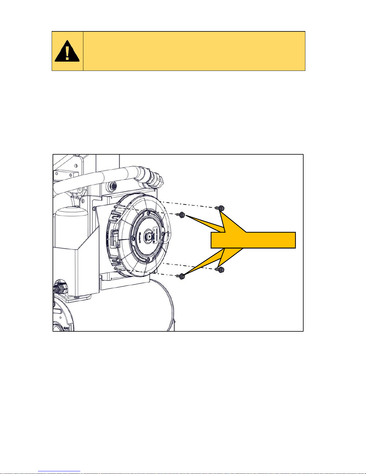
VMAC – Vehicle Mounted Air Compressors
VMAC Technical Support: 1-888-241-2289
VMAC Knowledge Base: www.kb.vmacair.com
78
WHASP Cooling Fan Replacement
Read the “Maintenance and Repair Safety” section prior to
performing any work on the system (beginning on Page 38).
Wear appropriate Personal Protective Equipment and follow
all industry standard safety practices.
Disconnect the electrical connector on the fan.
Remove the 4 bolts securing the fan to the WHASP Tank.
Apply Loctite 242 (blue) and install the new fan with the 4 bolts.
Reconnect the fan electrical connector.
Test the system.
Figure 67 – Remove WHASP Fan
Remove fasteners (4x)
Page 81
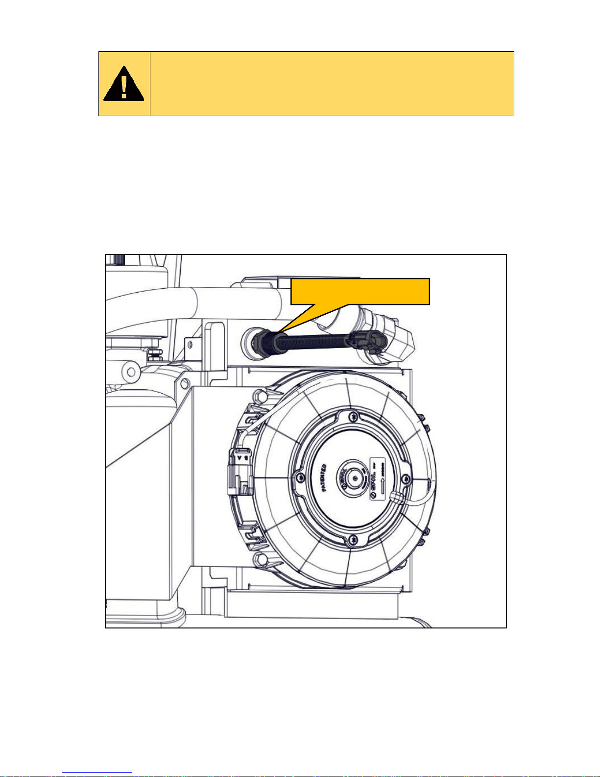
VMAC – Vehicle Mounted Air Compressors
VMAC Technical Support: 1-888-241-2289
VMAC Knowledge Base: www.kb.vmacair.com
79
Temperature Switch Replacement
Read the “Maintenance and Repair Safety” section prior to
performing any work on the system (beginning on Page 38 ).
Wear appropriate Personal Protective Equipment and follow
all industry standard safety practices.
Fan Switch Replacement
Disconnect the temperature switch from the harness.
Remove the temperature switch from the cooler on the WHASP Tank.
Apply Loctite 567 (thread sealant) to the new temperature switch and
install it into the WHASP Tank cooler.
Connect the temperature switch to the harness.
Figure 68 – Fan temperature switch removal
Temperature switch
Page 82
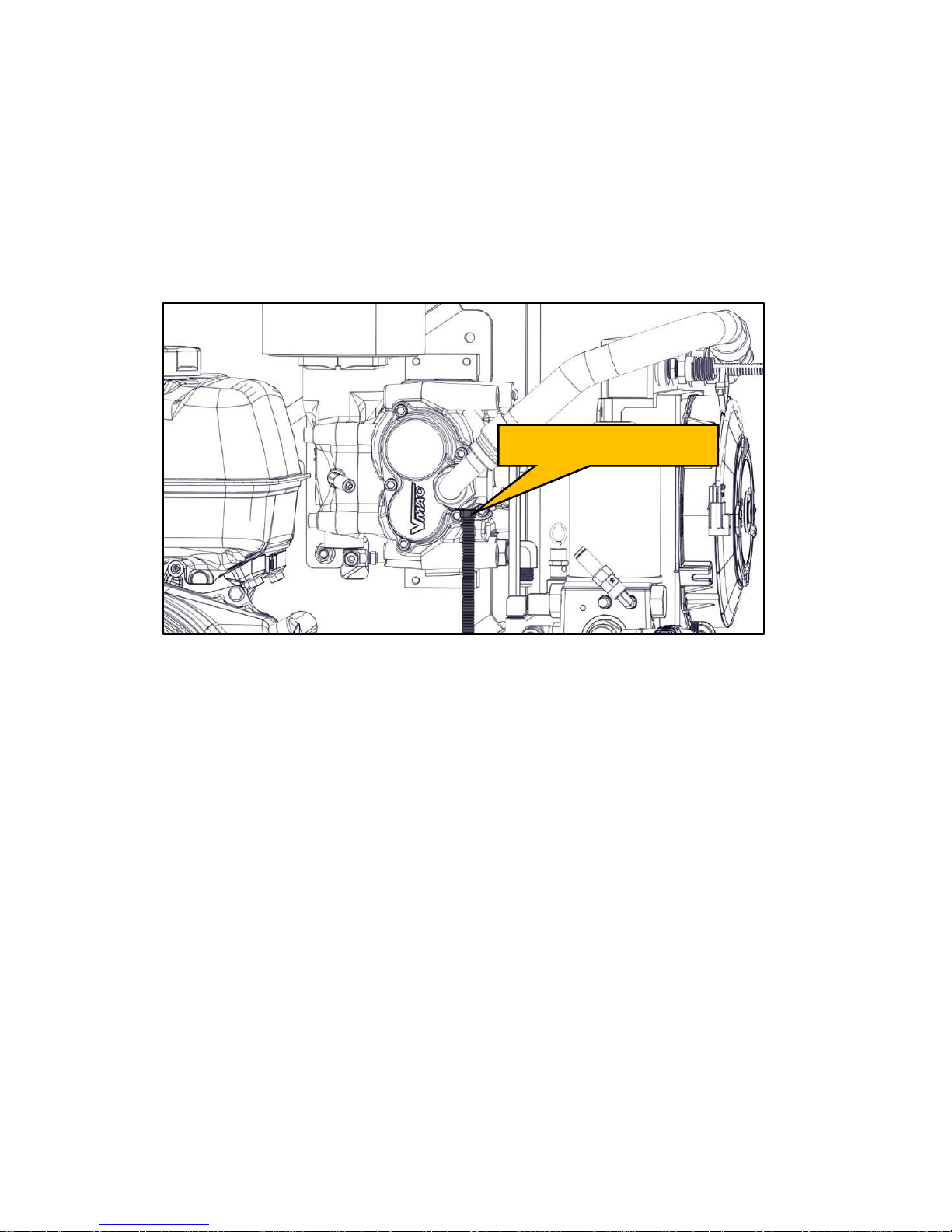
VMAC – Vehicle Mounted Air Compressors
VMAC Technical Support: 1-888-241-2289
VMAC Knowledge Base: www.kb.vmacair.com
80
Compressor Switch Replacement
Remove the WHASP Tank shroud.
Disconnect the temperature switch from the harness.
Remove the temperature switch from the compressor discharge cap.
Apply Loctite 567 (thread sealant) to the new temperature switch and
install it into the WHASP Tank cooler.
Connect the temperature switch to the harness.
Reinstall the WHASP Tank shroud.
Figure 69 – Compressor temperature switch removal
Temperature switch
Page 83
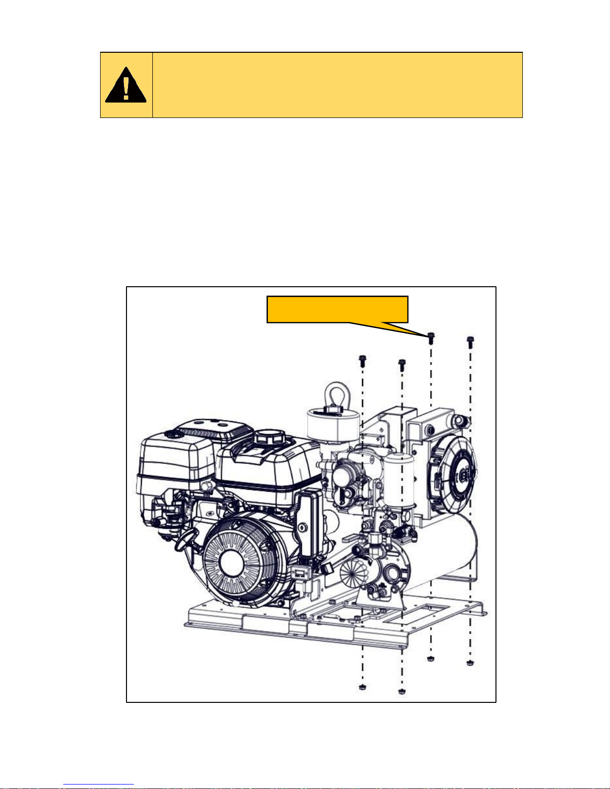
VMAC – Vehicle Mounted Air Compressors
VMAC Technical Support: 1-888-241-2289
VMAC Knowledge Base: www.kb.vmacair.com
81
WHASP Tank Replacement
Read the “Maintenance and Repair Safety” section prior to
performing any work on the system (beginning on Page 38 ).
Wear appropriate Personal Protective Equipment and follow
all industry standard safety practices.
Remove the WHASP Tank shroud.
Remove the battery.
Drain the compressor oil from the WHASP Tank (Page 48).
Disconnect the 3/4 in and 1/2 in hoses from the WHASP Tank.
Disconnect the PTFE tubes from the WHASP Tank.
Disconnect the electrical connectors from the fan and compressor
temperature switches.
Remove the 4 fasteners from the bottom of the WHASP Tank mounting
brackets.
Remove the WHASP Tank.
Figure 70 – Remove WHASP Tank
Install the WHASP Tank in the reverse order.
Remove fasteners (4x)
Page 84
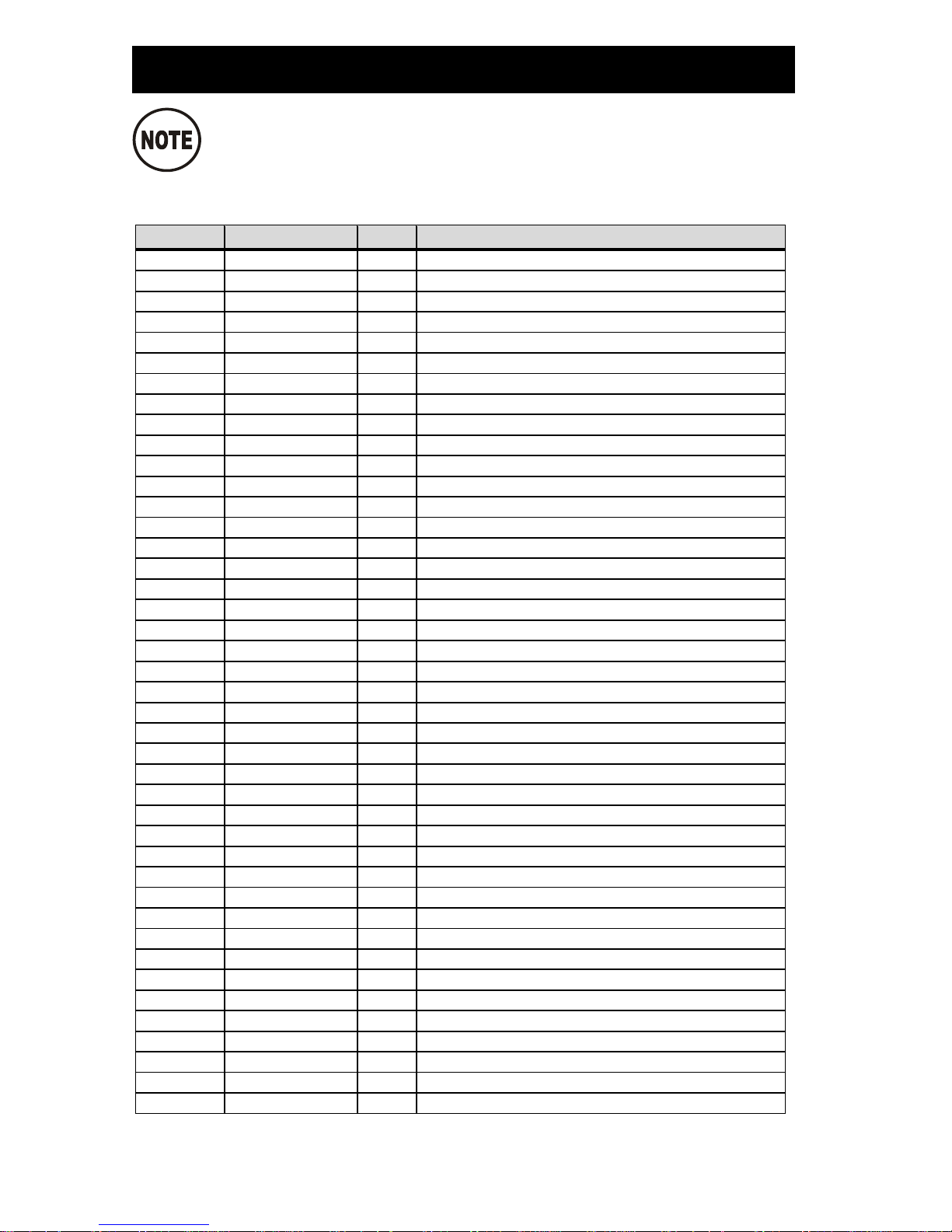
VMAC – Vehicle Mounted Air Compressors
VMAC Technical Support: 1-888-241-2289
VMAC Knowledge Base: www.kb.vmacair.com
82
Illustrated Parts List
Drawings are not to scale.
1. Kit Pack List
Item #
Part #
Qty
Description
1
1200993
1
MOUNT, PLATE
2
9500345
1
ENGINE, GAS, HONDA GX390
3
9500346
1
ARRESTER, SPARK, HONDA
4
1570484
1
WASHER, FLAT, SS, M5
5
4800782
1
ASSEMBLY, THROTTLE, PNEUMATIC
6
3501330
1
BATTERY, GROUP U1
7
1200995
1
PLATE, ENGINE
8
P190004
1
ASSEMBLY, COMPRESSOR
9
4800710
1
ASSEMBLY, PULLEY
10
1800242
1
PULLEY, CRANK
11
3200532
1
PAD, TENSIONER
12
3300036
1
TENSIONER 7C3Z-6B209-D
13
9240014
1
TANK, WHASP W/ UNLOADER, ASSEMBLED
14
1200997
1
BRACE, TOP
15
1510528
4
BOLT, HHCS NC G8 FL LK, 3/8 X 1
16
1520591
4
BOLT,HHCS, M8-1.25 X 25,G10.9 FL PL
17
1520627
14
BOLT, HHCS, FL PL, M8 X 1.25 X 20
18
1560515
14
NUT, M8 X 1.25 FL PL
19
1200996
1
BRACKET, LIFTING
20
1520629
2
BOLT,HHCS,GR10.9,PL,FL,M10X 1.5X 16
21
1200994
1
BRACKET, ENGINE PLATE
22
3501371
1
HOUR METER
23
1200999
1
BRACKET, SHROUD
24
1200859
1
GUARD, BELT
25
5800150
2
FOOTMAN LOOP, STEEL, 1.5" STRAP
26
1520643
4
BOLT,HHCS,G8.8 FL, M10 X 1.50 X 50
27
1560512
5
NUT, FLANGE PL, M10 X 1.5
28
1520605
1
BOLT,HHCS, M8-1.25 X 30, FL PL
29
1400424
1
SPACER
30
1560517
2
NUT, NYLOCK SS, M3
31
1500710
2
SCREW, SHCS, M3 X 14
32
1500711
9
CLIP, 1/4 ID, ROUTING
33
1200998
1
BRACE, BOTTOM
34
1772019
1
HOSE, CRIMPED, 3/4" X 19"
35
1520590
2
BOLT, HHCS, M6 X 1.0 X 14 FL PL
36
1560516
8
NUT, M6 X 1.0 FL PL
37
1520625
2
BOLT,HHCS FL PL, M6 X 1 X 25
38
1570514
2
WASHER, FLAT, ALUM, #6
39
1500667
4
SCREW, FLAT PHILLIPS,SS, M6X1 X16
40
3550936
1
CABLE, BATTERY, NEGATIVE
41
3550979
1
CABLE, BATTERY, POSITIVE
42
1812017
1
HOSE, CRIMPED, 3/8" X 17"
(Continued on next page)
Page 85
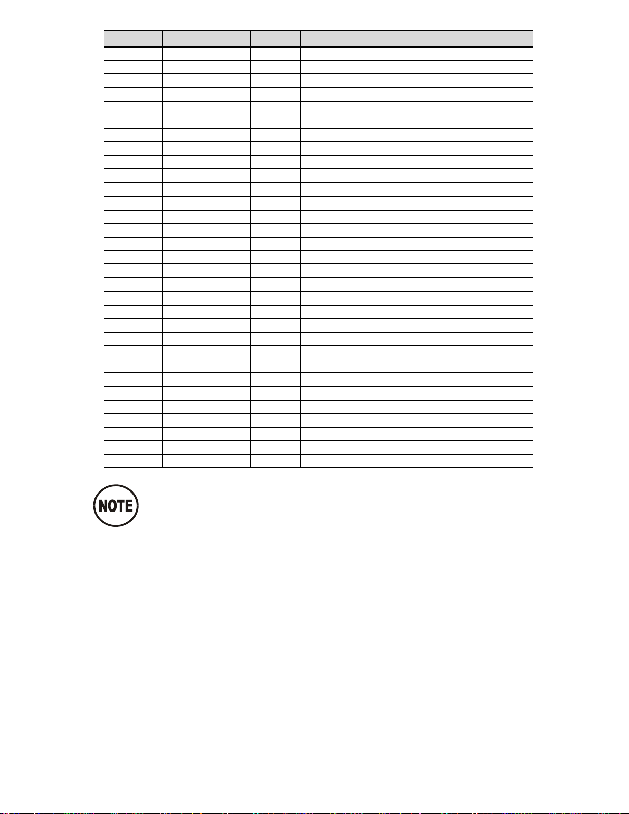
VMAC – Vehicle Mounted Air Compressors
VMAC Technical Support: 1-888-241-2289
VMAC Knowledge Base: www.kb.vmacair.com
83
Item #
Part #
Qty
Description
43
1520646
6
BOLT, HHCS G10.9, M6 X 1 X 10 FL PL
44
2200189
2
CLAMP, INSULATED, 3/8"
45
5800151
1
BATTERY STRAP, 1.5"X 54"
46
1400392
1
SPACER, CRANK PULLEY
47
1570496
1
WASHER, FENDER, 10MM X 30MM
48
1510550
1
BOLT, HHCS NF G8 PL, 3/8-24 X 1
49
1520626
1
BOLT,HHCS,PL,G10.9,FL, M6-1.0 X 30
50
4900167
1
CONN, 1/2 SWIVEL - 1/2 MALE NPT
51
3600159
1
VALVE, BALL, NPT-NPT, 1/2-1/2
52
1620365
1
BELT, K040438
53
1700584
10.0
SPIRAL WRAP, 1" OD, BLACK
54
5000218
1
FITTING, UNION TEE, 1/4" POLY
55
4401141
1
LABEL, WARNING, REFUELING
56
4400346
1
LABEL, SYSTEM ID PLATE
57
4401277
1
LABEL, G30
58
4401278
1
LABEL, OPERATING INSTR, G30
59
4400964
1
LABEL, SPECIALTY, WARNING
60
1500651
2
RIVET 1/8",GRIP RANGE-0.188"-0.250"
*61
3550975
1
HARNESS, GAS DRIVE
*62
3550984
1
HARNESS, FAN RELAY, GAS DRIVE
63
3501352
1
RELAY, WEATHERPROOF
*64
1700570
27.75
TUBE, TEFLON, PTFE,1/4"OD
*65
1700581
25.75
LOOM, SPLIT PLASTIC, 1/4, HIGH TEMP
*66
1700570
TUBE, TEFLON, PTFE,1/4"OD
*67
1700581
LOOM, SPLIT PLASTIC, 1/4, HIGH TEMP
*68
1700570
6.0
TUBE, TEFLON, PTFE,1/4"OD
*69
1700581
4.0
LOOM, SPLIT PLASTIC, 1/4, HIGH TEMP
*70
1700570
9.5
TUBE, TEFLON, PTFE,1/4"OD
*71
1700581
7.5
LOOM, SPLIT PLASTIC, 1/4, HIGH TEMP
*72
1700571
21.2
TUBE, TEFLON,PTFE, 3/16"OD X 1/8"ID
*73
1700581
19.0
LOOM, SPLIT PLASTIC, 1/4, HIGH TEMP
*Items 61-62, and 64-73 not shown in Figure 71.
Page 86
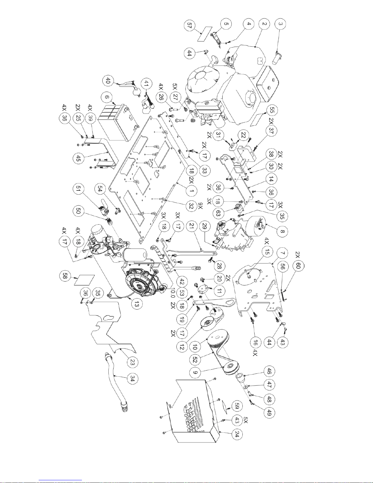
VMAC – Vehicle Mounted Air Compressors
VMAC Technical Support: 1-888-241-2289
VMAC Knowledge Base: www.kb.vmacair.com
84
Figure 71 - Kit Pack List
Page 87
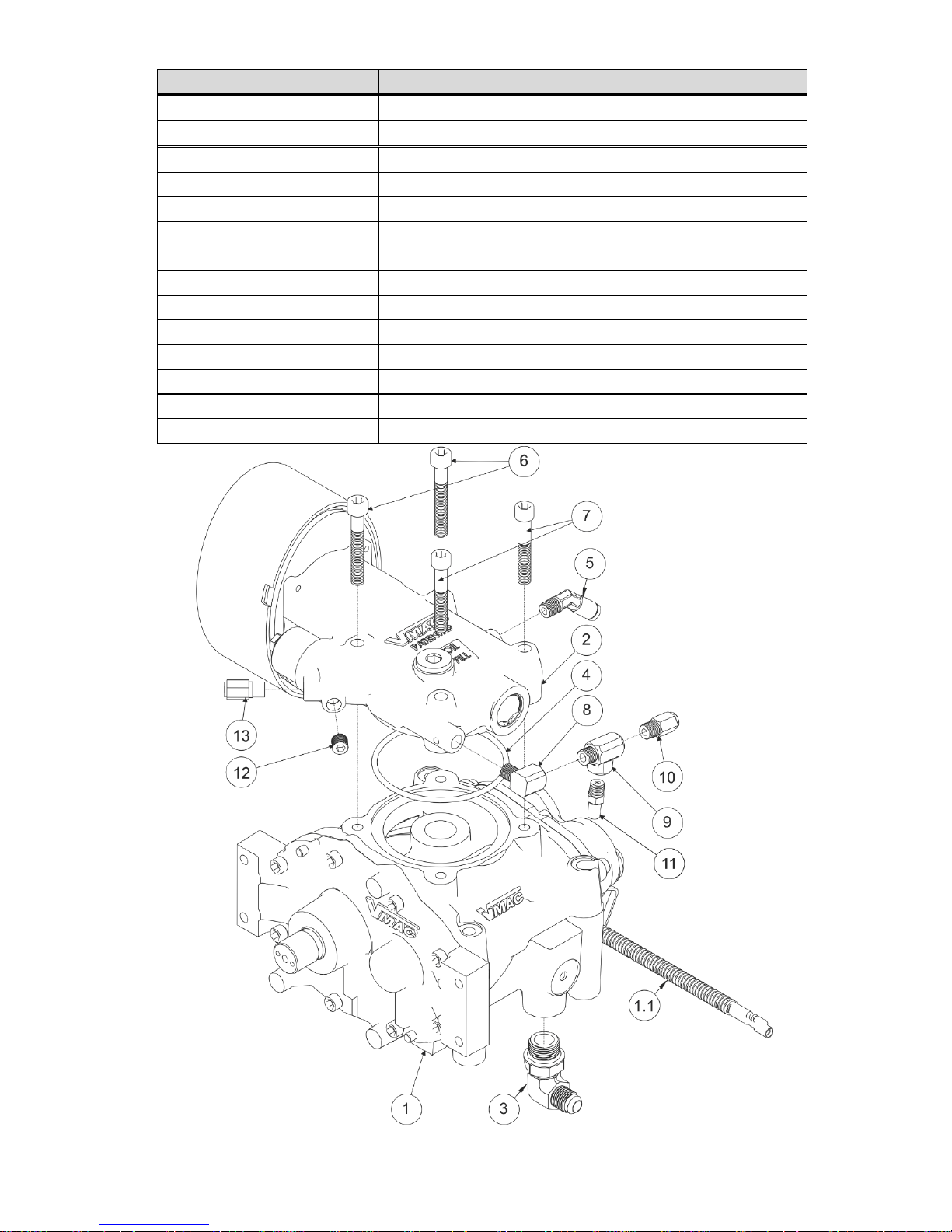
VMAC – Vehicle Mounted Air Compressors
VMAC Technical Support: 1-888-241-2289
VMAC Knowledge Base: www.kb.vmacair.com
85
2. Compressor Assembly, P190004
Item #
Part #
Qty
Description
1
P190005
1
ASSEMBLY, COMPRESSOR, GEARLESS
1.1
3550974
1
ASSEMBLY, SWITCH, THERMAL, 140C
2
9200570
1
ASSEMBLY, INLET VALVE
3
4900174
1
CONN, STEEL, 90, #6 JIC - #8 ORB
4
5830004
1
O-RING, VITON, 3 1/8 ID X 1/8
5
5000158
1
ELBOW,BRASS 45 DEG NPT-POLY 1/8-1/4
6
1540530
2
BOLT,SHCS,M8 X 1.25 X 55, G12.9 PLT
7
1540550
2
BOLT,SHCS,M8 X 1.25 X 50, G12.9 PLT
8
5000090
1
ELBOW, BRASS, EXTR'D 90 STREET, 1/8
9
5000121
1
TEE, STREET, EXTRUDED, 1/8
10
5000012
1
CONNECTOR, BRASS NPT-POLY, 1/8-1/4
11
3600185
1
ASSEMBLY, MUFFLER RESTRICTION
12
4300076
1
PIPE FTG, PLUG SKT HEAD, 1/8
13
5000162
1
CONNECT,BRASS NPT-POLY,3/16-1/8 NPT
Figure 72 – Compressor Assembly (P190004)
Page 88
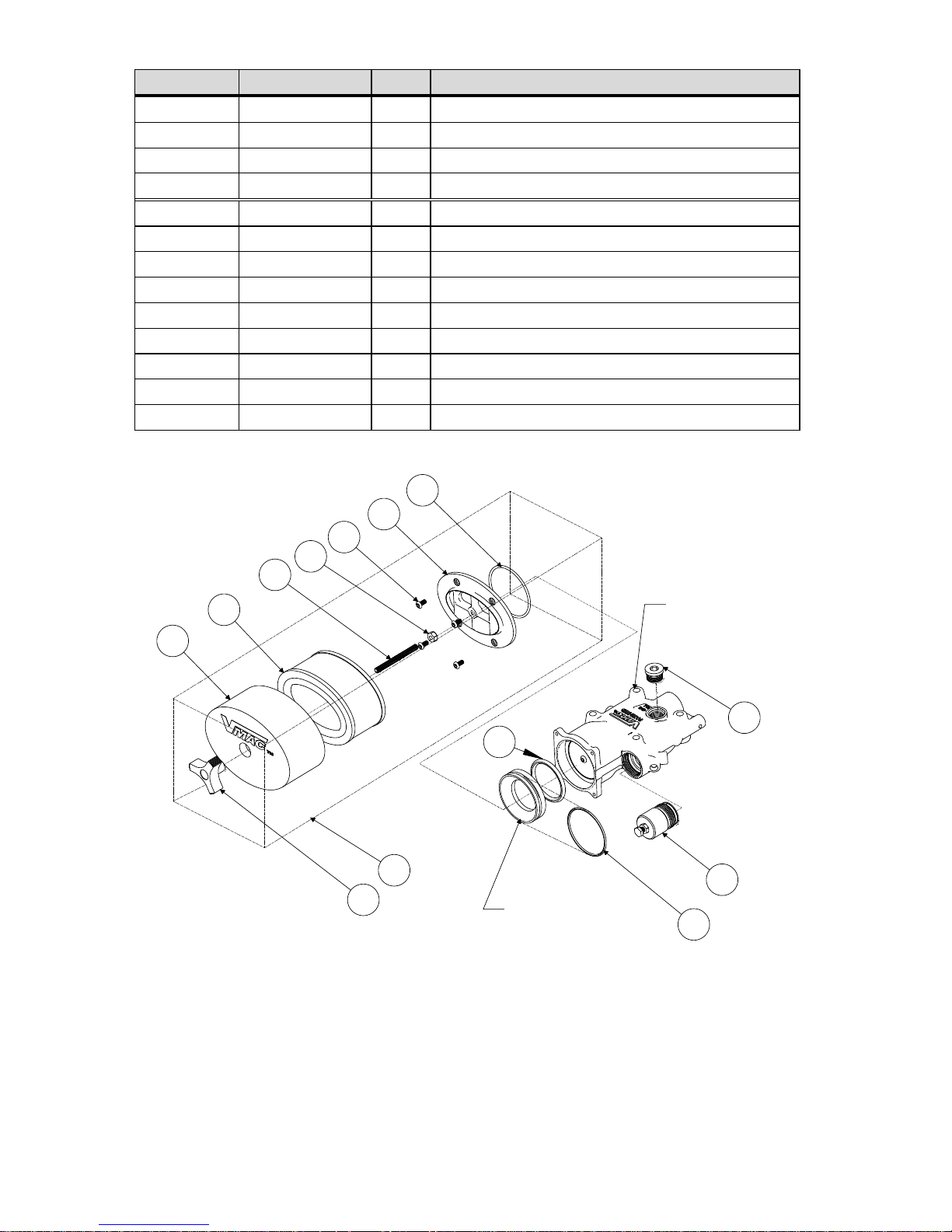
VMAC – Vehicle Mounted Air Compressors
VMAC Technical Support: 1-888-241-2289
VMAC Knowledge Base: www.kb.vmacair.com
86
3. Inlet Valve Sub Components, 9200570
Item #
Part #
Qty
Description
1
A700137
1
ACCESSORY PACK, REGULATOR ASSEMBLY
2
4900045
1
PLUG
3
5830002
1
O-RING, VITON, 2 3/8 ID X 3/32
4
5830160
1
O-RING, 40D SIL., 1 3/8 ID X 3/16
5
A700049
1
FILTER KIT ASSEMBLY
5.1
1500077
4
SCREW, BUTTON HEAD, 10 - 32 X 3/8
5.2
1500519
1
ROD, THREADED, 1/4 X 2.62
5.3
1500676
1
KNOB, PLASTIC, 1/4-20
5.4
1550221
1
NUT, HEX NC PL, 1/4, GR8
5.5
3200205
1
PLATE, INNER FILTER
5.6
3600037
1
ELEMENT, FILTER, PAPER
5.7
3600066
1
COVER, AIR FILTER, PLASTIC
5.8
5830070
1
O-RING, VITON, 2 9/16 ID X 3/32
Figure 73 – Inlet Valve Sub Components
5
1
3
2
4
5.1
5.2
5.3
5.4
5.5
5.6
5.7
5.8
shown for
reference only
shown for
reference only
Page 89
VMAC – Vehicle Mounted Air Compressors
VMAC Technical Support: 1-888-241-2289
VMAC Knowledge Base: www.kb.vmacair.com
87
4. WHASP Tank, 9240014
Item #
Part #
Qty
Description
1
3600054
1
VALVE, SAFETY 200 PSI
2
5000201
1
CONNECTOR,BRASS, NPT-POLY, 1/4-3/16
3
1200847
1
PLATE, MOUNT, BOLT ON
4
5000202
2
TEE, STREET, EXTRUDED, 1/4
5
5000219
1
ELBOW, BRASS, 1/4 MNPT - MNPT
6
5000204
1
ELBOW, 90, BRASS NPT-POLY, 1/4-1/4
7
3600178
1
VALVE, DISCHARGE, D4
8
5000012
1
CONNECTOR, BRASS NPT-POLY, 1/8-1/4
9
4900002
1
ELBOW, STEEL JIC/O-RING, 1/2 3/4-16
10
4500104
1
MUFFLER, SINTERED EXHAUST, 1/8"
11
3600171
1
VALVE, MODIFIED (3600167)
12
1520601
5
BOLT, HHCS FL PL, M8 X 1.25 X 12
13
1200852
1
PLATE, MOUNT, FILTER END
14
3200533
1
TUBE, OIL DRAIN
15
4900175
1
CONN, STEEL, #6 JIC - #8 ORB
16
4900117
1
JIC 90 DEG STEEL, SWIVEL, 3/8 -3/8
17
4900035
1
NIPPLE, STEEL STR THRD, 3/4 - 16
18
4900106
1
PLUG, STEEL, #5 ORB, HEX (VITON-O)
19
9200039
1
OIL FILTER, VR 3.250 SHORT
20
5830133
2
O-RING, VITON, #12
21
4900133
2
ELBOW, STEEL,JIC/ORB, 1 1/16-12
22
A700061
1
PYREX WINDOW KIT
23
4900163
1
CAP, STEEL, #12JIC
24
1500704
1
SCREW, CAP, HEX, 3/8-16 X 1/2
25
1570044
1
WASHER, ALLOY PL SAE, 3/8
26
1200903
1
BRACKET, UNLOADER
27
5000020
1
ELBOW, BRASS NPT-POLY, 1/8-1/4
28
3600177
1
VALVE, UNLOADER, RCT
29
5000140
1
ELBOW, BRASS,FORGED, 90DEG,1/8 PIPE
30
3600123
1
VALVE, CHECK, 1/8 NPT
31
5000212
1
CONNECTOR,BRASS, FNPT-POLY, 1/8-1/4
32
4900236
1
ELBOW, STEEL, 4MORB - 1/4MNPT
33
3600166
1
FITTING, NIPPLE, FILTER
34
6000719
1
SHROUD, FAN, WHASP TANK
35
1500691
6
SCREW, SELF TAPPING, #10-16 X 1/2
36
3550958
1
FAN, PULLER, 7.5", GT280
37
3600088
1
OIL SEPARATOR, SPIN-ON
(Continued on next page)
Page 90
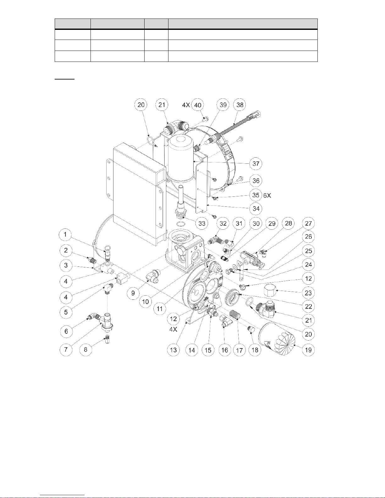
VMAC – Vehicle Mounted Air Compressors
VMAC Technical Support: 1-888-241-2289
VMAC Knowledge Base: www.kb.vmacair.com
88
Item #
Part #
Qty
Description
38
3550983
1
ASSEMBLY, SWITCH, THERMAL, 88C
39
5000047
1
BUSHING, BRASS, 3/8 X 1/4
40
1520590
4
BOLT, HHCS, M6 X 1.0 X 14 FL PL
Note: Item 33 includes O-rings.
Figure 74 – WHASP Tank
Page 91

VMAC – Vehicle Mounted Air Compressors
VMAC Technical Support: 1-888-241-2289
VMAC Knowledge Base: www.kb.vmacair.com
89
Warranty Registration
This form must be fully completed and returned to VMAC at the
time of installation. Warranty may be void if this form is not
received by VMAC within 30 days of installation.
VMAC’s Warranty policy and registration can be viewed online
at: www.vmacair.com/warranty
VMAC Dealer Information
Company Name: __________________________________________
City: _____________________ State / Province:_______________
Installer Information
Company Name: _____________________________________
City: _____________________ State / Province:______________
Installation Date: _____/_____/_____
Day Month Year
Owner Information
Company Name: __________________________________________
Address: ________________________________________________
City: _____________________ State / Province:_______________
Zip/Postal: ________________ Phone #: (____) ____ - _____
Email Address: ___________________________________________
Vehicle Information
Year: ____________________ Make: _________________
Vehicle Identification Number: ___________________________
Unit #: ___________________
Product Information
System Identification Number: G _ _ _ _ _ _ _ _ _ _ _ _
Submitted by
Name: ____________________ Contact: _________________
Page 92

VMAC – Vehicle Mounted Air Compressors
VMAC Technical Support: 1-888-241-2289
VMAC Knowledge Base: www.kb.vmacair.com
90
This page intentionally left blank
Page 93
VMAC – Vehicle Mounted Air Compressors
VMAC Technical Support: 1-888-241-2289
VMAC Knowledge Base: www.kb.vmacair.com
91
Service Records
The engine and compressor must be serviced as per the manufacturer’s
specifications for the warranty to be considered valid.
Maintenance and Repair Records
200 Hour or 6 month service (P/N: A700219)
Date:
Hours
Performed by:
Address 1:
Address 2:
Notes:
400 Hour or 12 month service (P/N: A700220)
Date:
Hours
Performed by:
Address 1:
Address 2:
Notes:
Page 94
VMAC – Vehicle Mounted Air Compressors
VMAC Technical Support: 1-888-241-2289
VMAC Knowledge Base: www.kb.vmacair.com
92
600 Hour or 18 month service (P/N: A700219)
Date:
Hours
Performed by:
Address 1:
Address 2:
Notes:
800 Hour or 24 month service (P/N: A700220)
Date:
Hours
Performed by:
Address 1:
Address 2:
Notes:
1000 Hour or 30 month service (P/N: A700219)
Date:
Hours
Performed by:
Address 1:
Address 2:
Notes:
Page 95
VMAC – Vehicle Mounted Air Compressors
VMAC Technical Support: 1-888-241-2289
VMAC Knowledge Base: www.kb.vmacair.com
93
1200 Hour or 36 month service (P/N: A700220)
Date:
Hours:
Performed by:
Address 1:
Address 2:
Notes:
1400 Hour or 42 month service (P/N: A700219)
Date:
Hours:
Performed by:
Address 1:
Address 2:
Notes:
1600 Hour or 48 month service (P/N: A700220)
Date:
Hours:
Performed by:
Address 1:
Address 2:
Notes:
Page 96
VMAC – Vehicle Mounted Air Compressors
VMAC Technical Support: 1-888-241-2289
VMAC Knowledge Base: www.kb.vmacair.com
94
1800 Hour or 54 month service (P/N: A700219)
Date:
Hours:
Performed by:
Address 1:
Address 2:
Notes:
2000 Hour or 60 month service (P/N: A700220)
Date:
Hours:
Performed by:
Address 1:
Address 2:
Notes:
Page 97

This page intentionally left blank
Page 98

This page intentionally left blank
Page 99

Page 100
 Loading...