

Vmac AIR INNOVATED H400001, AIR INNOVATED H600008, AIR INNOVATED H600004, AIR INNOVATED H400003, AIR INNOVATED H600002 Installation And Owner's Manual

®
AIR INNOVATED
TM
www.vmacair.com
Hydraulic Driven Air Compressor
Installation and Owner’s Manual
(Includes Service Instructions)
®
AIR INNOVATED
TM


VMAC - Vehicle Mounted Air Compressors
VMAC Technical Support: 888-241-2289
VMAC Knowledge Base: www.kb.vmacair.com
1
Table of Contents
General Information .................................................3
Safety ..............................................................4
Safety Precautions ..................................................5
Warranty ...........................................................8
Hydraulic Driven Air Compressor Installation Manual ........... 11
Installation Considerations ......................................... 13
Mounting Locations and Ventilation ................................14
Speed Control .....................................................16
Hydraulic Requirements ............................................ 17
Hydraulic Fluid and Line Sizing Recommendations ..................19
Hydraulic Driven Air Compressor Harness Reference ............... 22
Electrical Requirements (12 V dc Systems) ......................... 24
Electrical Requirements (24 V dc Systems) ......................... 26
Installing the Hydraulic Driven Air Compressor System ............. 28
Testing the Installation .............................................31
Performance Testing and System Adjustments ..................... 33
Hydraulic Driven Air Compressor Owner’s Manual ..............35
Identifying Your System ............................................37
System Components and Specifications ........................... 38
System Operation (What to Expect at Start Up) ................... 45
Cold or Hot Weather Operation ................................... 48
Display Box Messages ............................................ 49
System Adjustments (Diagnostics Mode) ...........................51
Limp Mode ....................................................... 53
General Maintenance Information ................................. 54
Maintenance and Repair Safety ................................... 56
Regular Inspection Instructions .................................... 58
500 Hour / 1 Year Service ..........................................62
Diagnostics and Troubleshooting .................................. 69
Hydraulic Testing ..................................................77
Air Receiver Tank...................................................81
Recommended Accessories ....................................... 82
Accessory Products from VMAC ................................... 83
Error and Service Logs ............................................ 86
Warranty Registration ............................................. 88

VMAC - Vehicle Mounted Air Compressors
VMAC Technical Support: 888-241-2289
VMAC Knowledge Base: www.kb.vmacair.com
2
Document: 1930366
Changes and Revisions
Revision Revision Details Revised by
Checked by
Implemented
Eng.
Tech. Qual.
Mech. Elec.
A Initial Release MSP MRH N/A GB AWM 16 Oct 2018
Additional Application Information
This manual applies to: H400001 / H400003 / H600002 / H600004 / H600008.
•
Not compatible with “load sensing” variable displacement pumps.
•
Requires VMAC Closed Center Manifold if used with “pressure compensated”
variable displacement pumps:
Important Information
The information in the installation section of this manual is intended for certified
VMAC installers who have been trained in installation procedures and/or for
people with mechanical trade certification who have the tools and equipment
to properly and safely perform the installation. Do not attempt this installation
without the appropriate mechanical training, knowledge and experience.
Follow all safety precautions while operating the equipment as well as when
performing any mechanical work. Any fabrication for correct fit in modified vehicles
must follow industry standard “best practices”.
Notice
Copyright © 2018 VMAC Global Technology Inc. All Rights Reserved. These
materials are provided by VMAC for informational purposes only, without
representation or warranty of any kind, and VMAC shall not be liable for errors
or omissions with respect to the materials. The only warranties for VMAC
products and services are those set forth in the express warranty statements
accompanying such products and services, if any, and nothing herein shall be
construed as constituting an additional warranty. Printing or copying of any page
in this document in whole or in part is only permitted for personal use. All other
use, copying or reproduction in both print and electronic form of any part of this
document without the written consent of VMAC is prohibited. The information
contained herein may be changed without prior notice.
Printed in Canada
Registered Trademarks
All trademarks mentioned in this manual are the property of their respective
owners. VMAC’s use of manufacturers’ trademarks in this manual is for
identification of the products only and does not imply any affiliation to, or
endorsement of said companies.
Loctite®, Loctite® 242 and Loctite® 567 are registered trademarks of Henkel AG &
Company KGaA.
Eaton Aeroquip® is a registered trademark of EATON AEROQUIP INC.
Viton® is a registered trademark of The Chemours Company.
VMAC - Vehicle Mounted Air Compressors
VMAC Technical Support: 888-241-2289
VMAC Knowledge Base: www.kb.vmacair.com
3
Introduction
This manual provides operating instructions, specifications, adjustment,
maintenance and warranty information for the VMAC Hydraulic Driven Air
Compressor systems. Read this manual prior to servicing or operating the
compressor system.
Follow all safety precautions when servicing or operating the VMAC system as
moving fan blades and other rotating components pose an extreme hazard.
Proper service and repair are important to the safety of the operator and the safe,
reliable operation of the equipment. Always use genuine VMAC replacement parts.
The procedures described in this manual are the only approved methods of service
and operation.
Ordering Parts
To order parts, contact a VMAC dealer. The dealer will ask for the VMAC System ID
(see page 37), part number, description and quantity. Locate the nearest dealer
online at www.vmacair.com/dealer-locator or call 1-877-912-6605.
General Information
Additional Support
Additional resources such as installation manuals, illustrated parts lists, the VMAC
Knowledge Base, air tool consumption guides, etc. are available at
https://www.vmacair.com/support/.
VMAC is unable to provide hydraulic circuit designs or consult on
specific hydraulic installations. We recommend working with a local
hydraulic expert to design and/or install the hydraulic circuit that
will power the Hydraulic Driven Air Compressor system.
VMAC - Vehicle Mounted Air Compressors
VMAC Technical Support: 888-241-2289
VMAC Knowledge Base: www.kb.vmacair.com
4
Important Safety Notice
The information contained in this manual is based on sound engineering principles,
research, extensive field experience and technical information. Information
is constantly changing with the addition of new models, assemblies, service
techniques and running OEM changes. If a discrepancy is found in this manual,
contact VMAC prior to initiating or proceeding with installation, service or repair.
Current information may clarify the issue. Any person with knowledge of such
discrepancies, who proceeds to perform service and repair assumes all risks.
Only proven service procedures are recommended. Anyone who departs from the
specific instructions provided in this manual must first assure that their safety and
that of others is not being compromised and that there will be no adverse effects
on the operational safety or performance of the equipment.
VMAC will not be held responsible for any liability, consequential damages, injuries,
loss or damage to individuals or to equipment as a result of the failure of any
person to properly adhere to the procedures set out in this manual or standard
safety practices. Safety should be the first consideration when performing any
service operations. If there are any questions concerning the procedures in this
manual or more information is required, please contact VMAC before beginning
repairs.
Safety Messages
This manual contains various warnings, cautions and notices that must be
observed to reduce the risk of personal injury during installation, service or repair
and the possibility that improper installation, service or repair may damage the
equipment or render it unsafe.
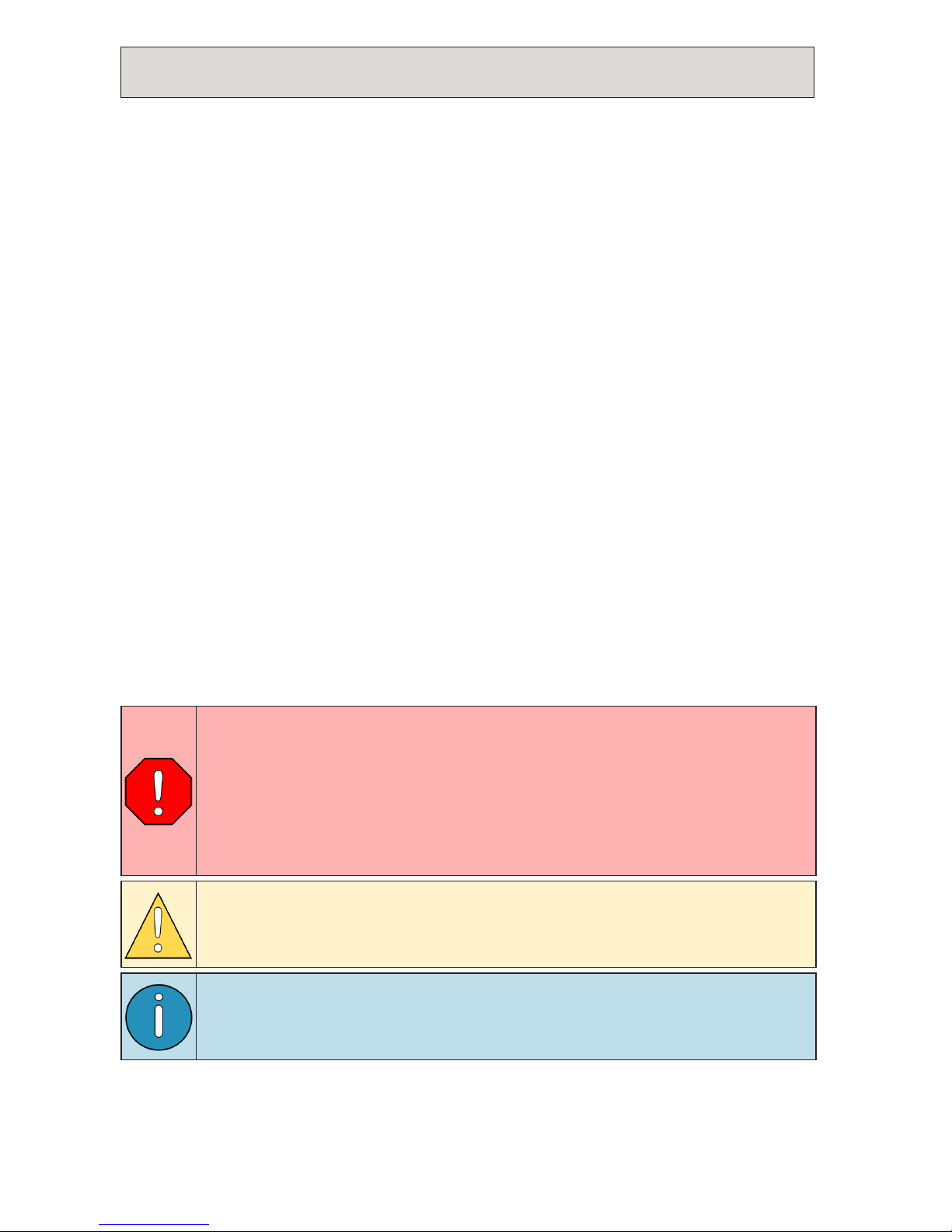
This symbol is used to call attention to instructions concerning
personal safety. Watch for this symbol; it points out important
safety precautions, it means, “Attention, become alert! Your
personal safety is involved”. Read the message that follows and
be aware of the possibility of personal injury or death. As it is
impossible to warn of every conceivable hazard, common sense and
industry standard safety practices must be observed.
This symbol is used to call attention to instructions on a specific
procedure that if not followed may damage or reduce the useful life
of the compressor or other equipment.
This symbol is used to call attention to additional instructions or
special emphasis on a specific procedure.
Safety
VMAC - Vehicle Mounted Air Compressors
VMAC Technical Support: 888-241-2289
VMAC Knowledge Base: www.kb.vmacair.com
5
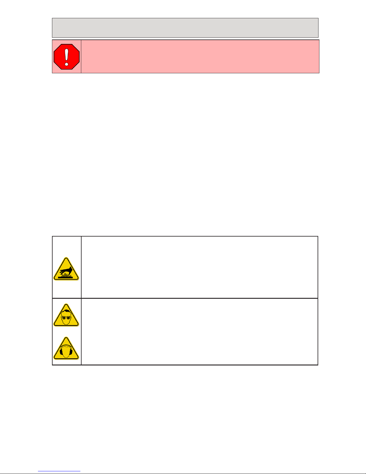
Burn Hazard
•
The compressor system gets very hot during operation, contact
with the components or the oil can cause serious injury. Allow
sufficient time for the system to cool before performing service.
•
Never allow any part of your body to contact the compressor
components.
Personal Safety
•
Do not breathe the compressor air. Vaporized oil is a respiratory
hazard.
•
Always use the appropriate personal protective equipment,
particularly eye and hearing protection when operating air
powered equipment.
As it is impossible to warn of every possible hazard that may result
from operating this system, common sense and industry standard
safety practices must be observed.
Read this information before operating the compressor for the first time. Follow
the information and procedures in this manual for operation, maintenance and
repair. Observe the following items to reduce the chance of personal injury or
equipment damage.
Follow all safety precautions for mechanical work. Moving belts and rotating
components are an extreme hazard. Stay clear of all moving parts when the
system is operating. Only qualified personnel should perform maintenance and
repair on system components and only while the system is properly shut down.
Proper service and repair are important to the safety of the service technician
and the safe, reliable operation of the equipment. Always use genuine VMAC
replacement parts.
The procedures described in this service manual are effective methods of service
and repair. Some procedures may require the use of tools specially designed for a
specific purpose. Anyone using a replacement part, service procedure or tool must
first determine that neither their safety nor the safe operation of the equipment
will be compromised by the replacement part, service procedure or tool selected.
Safety Precautions
VMAC - Vehicle Mounted Air Compressors
VMAC Technical Support: 888-241-2289
VMAC Knowledge Base: www.kb.vmacair.com
6
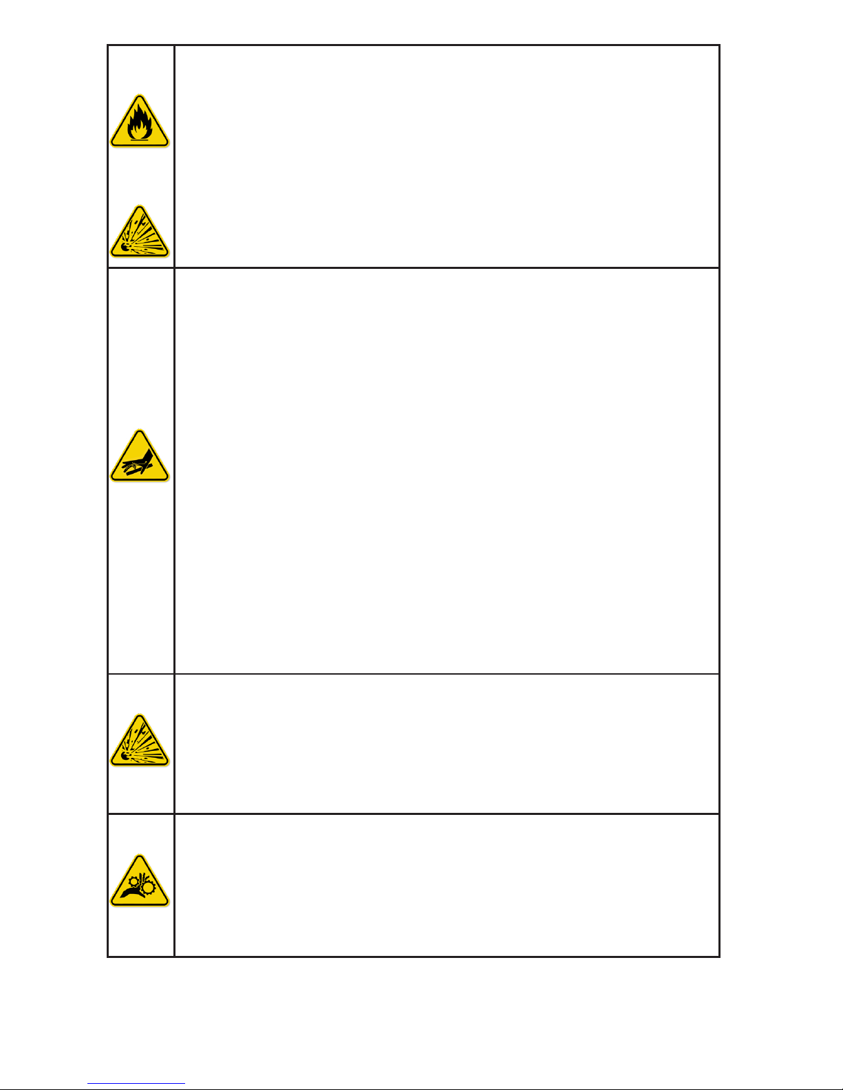
Fire and Explosion Hazard
•
Vaporized oil propelled by high pressure air is an explosive mixture.
•
Fire in the compressor can cause an explosion and flame projection.
Should this occur, there is potential for serious injury or death.
•
Operate the compressor in a well ventilated area free of flammable
vapors, dust, or other combustible materials.
•
Never place objects against or on top of the compressor.
•
Never expose the Air Oil Separator Tank or compressor to extreme
heat.
Compressor Air and Oil Hazard
•
The compressor system is under sufficient pressure that a leak
could force the air/oil mixture through the skin directly into your
bloodstream. This could cause serious injury or death.
•
Ensure the system is completely depressurized before attempting
maintenance or repair.
•
Do not use compressed air to clean off clothing or skin, compressed
air can penetrate the skin causing serious injury or death.
•
Do not move or service the compressor while it is pressurized or
operating.
•
Do not move the compressor by pulling on any hoses.
•
Components and hoses under pressure could separate suddenly, fly
out and cause serious injury or death. If equipped, the air receiver
tank must be drained before servicing any components in the
compressor system.
•
Never adjust or attempt to make any repairs to the system while
the engine is running. Components and hoses under pressure could
fail and cause serious injury or death.
Burst Hazard
•
Serious injury or death may result from an air tank explosion.
•
Never exceed manufacturer’s maximum air pressure rating.
•
Do not repair components, only replace with approved parts.
•
Do not tamper with or disable factory safety equipment.
Moving Parts Hazard
•
Before performing service, disconnect the negative battery cable
and the spark plug wire to prevent unexpected engine start.
•
Do not operate the compressor without guards in place. If the
guards are damaged or missing, replace them before operating the
equipment.
VMAC - Vehicle Mounted Air Compressors
VMAC Technical Support: 888-241-2289
VMAC Knowledge Base: www.kb.vmacair.com
7
General Warnings
•
Ensure the compressor and hydraulic system are cool and
depressurized prior to servicing.
•
Be attentive for unexplained changes in operation parameters and
record any changes.
•
Check the compressor oil level and condition before starting the
system. Do not add or change oil while the system is running. Use
only approved oil.
•
The compressor may operate anytime the hydraulic circuit is
energized. Avoid contact with the compressor, hoses, or motor
during operation.
•
Keep hoses and wiring away from hot, sharp, or moving
components.
•
Use only approved hoses and replacement parts.
•
Do not modify the equipment.
•
Do not operate the air compressor when fatigued or under the
influence of alcohol or drugs.
•
Know how to operate the compressor, fully read the manual.
•
Check equipment before every use.
•
Never bypass or disable any of the safety equipment.
•
Never adjust or attempt to make any repairs to the compressor
system while the hydraulic circuit is pressurized. Components and
hoses under pressure could fail and cause serious injury or death.
VMAC - Vehicle Mounted Air Compressors
VMAC Technical Support: 888-241-2289
VMAC Knowledge Base: www.kb.vmacair.com
8
VMAC Standard Warranty (Limited)
For complete warranty information, including both VMAC Standard
Warranty (Limited) and VMAC Lifetime Warranty (Limited)
requirements, please refer to our current published warranty located
at: www.vmacair.com/warranty
If you do not have access to a computer, please contact us and we
will be happy to send you our warranty.
VMAC’s warranty is subject to change without notice.
VMAC Lifetime Warranty (Limited)
A VMAC Lifetime Limited Warranty is offered
on the base air compressor only and only on
UNDERHOOD, Hydraulic Driven, Transmission
Mounted, Gas and Diesel Engine Driven Air
Compressors, Multifunction Power Systems, and
other products as defined by VMAC, provided that
(i) the purchaser fully completes and submits a
warranty registration form within 3 months of purchase, or 200 hours of operation,
whichever occurs first; (ii) services are completed in accordance with the Owner’s
Manual; (iii) proof of purchase of applicable service kits are made available to
VMAC upon request.
The VMAC Lifetime Warranty is applicable to new products shipped on or after
1 October, 2015.
Warranty Registration
The VMAC warranty registration form is located near the back of this manual. This
warranty registration form must be completed and sent to VMAC at the time of
installation for any subsequent warranty claim to be considered valid.
There are 4 ways the warranty can be registered with VMAC:
www.vmacair.com/warranty
warranty@vmacair.com
(877) 740 -3202
VMAC - Vehicle Mounted Air Compressors
1333 Kipp Road, Nanaimo, BC, Canada V9X 1R3
LIFETIME
A
I
R
I
N
N
O
V
A
T
E
D
T
R
U
S
T
S
E
R
V
I
C
E
V
A
L
U
E
WARRANTY
Warranty
VMAC - Vehicle Mounted Air Compressors
VMAC Technical Support: 888-241-2289
VMAC Knowledge Base: www.kb.vmacair.com
9
VMAC warranty work must be pre-authorized by VMAC. Claims are
processed via our dealer network. If you are not a VMAC dealer,
please select one to work with via our Dealer Locator:
https://www.vmacair.com/dealer-locator/.
1. Communicate with VMAC Technical Support at 1-888-241-2289 to help diagnose/
troubleshoot the problem prior to repair. VMAC technical support requires the
VMAC System ID, hours on the compressor and mileage on the vehicle.
2. VMAC will provide direction for repair or replacement of the failed components.
3. Failed parts must be held by the dealer for a period of six months, and sent to
VMAC if requested (along with the RMA number) for evaluation, unless otherwise
instructed by VMAC.
4. Dealers may login to the VMAC website to view the VMAC Labour Time Guide
(under “Agreements”) to see the allowable warranty labour times.
5. Warranty invoices must include the Service Ticket (CSR) number, VMAC System
ID#, hours on the compressor, mileage on the vehicle, and a detailed description
of the work performed.
6. VMAC Warranty does not cover consequential damage, overtime charges,
mileage, travel time, towing/recovery, cleaning or shop supplies.
7. Dealers submit warranty claims on behalf of the Vehicle Owner/End User
affected by the defective part(s). The dealer ensures that all warranty credits
are refunded back to the Vehicle Owner/End User who made the initial warranty
claim.
For Standard Warranty (Limited): If the completed warranty
registration form has not been received by VMAC within 6 months
from the date of installation of the Product(s), the warranty period
will be deemed to commence 30 days from the date of shipment
from VMAC.
For Lifetime Warranty (Limited): The completed warranty
registration form must be received by VMAC within 3 months from
the date of purchase or 200 hours of operation of the product(s)
(whichever occurs first).
Failure to follow this procedure may result in denial of the warranty
claim.
VMAC Product Warranty Policies & Warranty Registration can be found on the
VMAC website (see previous page for URL).
VMAC Warranty Claim Process

Hydraulic Driven Air Compressor
Installation Manual
®
AIR INNOVATED
TM

VMAC - Vehicle Mounted Air Compressors
VMAC Technical Support: 888-241-2289
VMAC Knowledge Base: www.kb.vmacair.com
13
Installation Considerations
Prior to installing the system, consider the following factors:
•
For proper operation, VMAC’s Hydraulic Driven Air Compressor Systems require
proper hydraulic pressure and flow, ensure the hydraulic circuit is designed
with these requirements in mind (see page 17).
•
See “Hydraulic Fluid and Line Sizing Recommendations” on page 19 for
additional hydraulic circuit recommendations.
•
Special consideration is required for variable rate hydraulic pumps
(see page 17). Is the intended location convenient for electrical, hydraulic,
and air connections?
•
Will the intended location require extensive plumbing for the hydraulic system
or air hoses?
•
Are the wire lengths, and air/hydraulic hose lengths as short as possible, and
with the least amount of 90° fittings possible?
•
Can the oil level at the sight glass be checked easily?
•
Can the unit be serviced easily?
•
Will there be adequate clearance around the unit to provide good air
circulation and effective cooling (see page 14)?
•
Will the unit be protected from excessive exposure to the elements?
•
Will the unit be protected from incidental damage from other operations?
•
Will the unit be mounted away from heat sources such as engines, exhaust, or
other components that can generate heat.
•
Will the unit be mounted where it will be exposed to high contamination levels,
including combustible gases?
•
If the intended mounting location is constructed of thin gauge material,
consider using the VMAC Mounting Brackets (P/N: A700140).
The information in this section is critical to ensure proper operation
of the system. Read these requirements prior to beginning the
installation.
Failure to adhere to these recommendations will cause the
Hydraulic Driven Air Compressor system to operate erratically.
The integrated cooler on the Hydraulic Driven Air Compressor
system is capable of removing all of the heat generated during air
compression from the compressor oil and hydraulic fluid.
Additional hydraulic oil cooling (such as VMAC’s Hydraulic Oil Cooler
(P/N: A850001) may be required for any other hydraulic equipment
installed on the same circuit.
VMAC - Vehicle Mounted Air Compressors
VMAC Technical Support: 888-241-2289
VMAC Knowledge Base: www.kb.vmacair.com
14
Enclosed mounting is not recommended due to the significant heat
generated by the Hydraulic Driven Air Compressor.
While it is not possible to make absolute recommendations regarding ventilation
due to the widely differing circumstances that are possible, duty cycle, ambient
temperature and enclosure shape are some of the important variables that must
be considered.
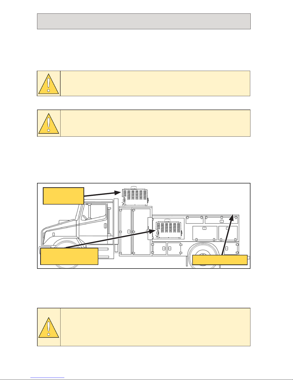
Top Mounting
“Top mounted” is the preferred mounting location for the Hydraulic Driven Air
Compressor. Placing the unit on top of the service body provides the best access to
cool fresh air. Maintain a minimum of 6 in between the sides of the Hydraulic Driven
Air Compressor and all other solid objects (Figure 1).
Mounting Locations and Ventilation
Mounting the Hydraulic Driven Air Compressor in an enclosure will limit access
to cool fresh air, restrict the escape of hot air from around the unit and have an
adverse effect on cooling which may reduce the unit’s duty cycle. Ensure adequate
ventilation is provided for cooling and to evacuate the heat generated by the unit.
If mounting in an enclosure, VMAC strongly recommends mounting the unit on a
pullout drawer and extending the drawer any time the unit is run.
Figure 1 — Mounting locations
Enclosure mounted
(not recommended)
Top mounted
(Preferred)
Not recommended
VMAC does not recommend mounting the unit at the back of the
vehicle as the drag created when the vehicle is moving causes
debris to be deposited (and accumulated) inside the unit.
Significant ventilation and additional cooling will be required if the
Hydraulic Driven Air Compressor is mounted in the same enclosure
as the hydraulic oil reservoir. The heat generated during operation
will continue to heat the hydraulic fluid (even with fresh ambient air
entering the cooler).
Enclosed Mounting
VMAC - Vehicle Mounted Air Compressors
VMAC Technical Support: 888-241-2289
VMAC Knowledge Base: www.kb.vmacair.com
15
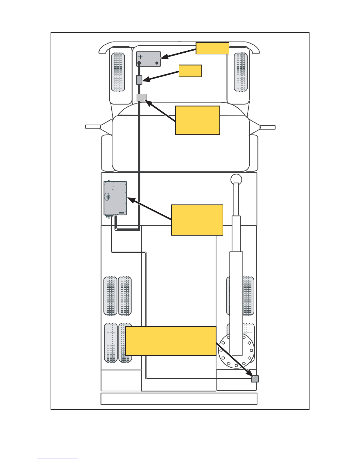
Recommended Component Layout
Figure 2 — Recommended component layout
Battery
Fuse
Ignition
switched
relay
Hydraulic
Driven Air
Compressor
Display Box
(mounted inside weather
proof enclosure)

VMAC - Vehicle Mounted Air Compressors
VMAC Technical Support: 888-241-2289
VMAC Knowledge Base: www.kb.vmacair.com
16
Speed Control
The Hydraulic Driven Air Compressor has the ability to signal for a higher engine
speed under high air demand conditions and for a lower engine speed under low
air demand conditions. A built in, electrically activated idle up system or an aftermarket product is required to provide 2 speed operation.
The Hydraulic Driven Air Compressor is capable of constant operation at a
fixed engine speed and hydraulic pump gpm. There are several advantages to
configuring the system for 2 speed operation:
•
Lower fuel consumption.
•
Lower noise when air demand is low.
•
Lower wear rates on the engine, hydraulic pump and compressor.
•
Faster warm up during cold start weather.
The preferred approach for speed control is to restrict the hydraulic flow to the
Hydraulic Driven Air Compressor to the minimum requirement for the system (8 – 9
gpm for the H40, 13 – 14 gpm for the H60 and H60 HHP) this is desirable for cold
climate start-up as it keeps hydraulic pressure low during warm up.
The system must be at, or above, the minimum hydraulic flow before
starting the Hydraulic Driven Air Compressor.
Single Speed Operation (See Figure 3 on page 17 for “gpm vs cfm” chart)
When the “ON” button is pressed, the Control Box in the Hydraulic Driven Air
Compressor will signal the PTO to increase hydraulic flow to provide the desired
cfm.
2 Speed Operation (See Figure 3 on page 17 for “gpm vs cfm” chart)
When the “ON” button is pressed, “Speed 1” is activated and the Control Box in
the Hydraulic Driven Air Compressor will signal the PTO to set hydraulic flow to the
minimum desired cfm.
“Speed 2” is activated to signal the PTO to increase hydraulic flow to provide the
maximum cfm (or speed system warm up).
Remote ON/OFF Control (Optional)
The system can be configured with a remote “ON/OFF” control by connecting the
yellow remote wire on the harness to a switch or relay and connecting the other
side of the switch or relay to ground. The Hydraulic Driven Air Compressor will
turn on when the circuit between the yellow wire and ground is completed via
the switch or relay and will turn off when the switch or relay is used to open the
circuit.
During this time, the Display Box can only be used to view messages as the “ON”
and “OFF” buttons are disabled.
VMAC - Vehicle Mounted Air Compressors
VMAC Technical Support: 888-241-2289
VMAC Knowledge Base: www.kb.vmacair.com
17
Hydraulic Requirements
H40 / H60
While in operation, the required system pressure will vary between 900 psi and
2,400 psi.
The hydraulic pump must be rated for 2,400 psi (steady state) and 2,800 psi
(intermittent) to allow for an additional 200 psi pressure drop in the pressure lines
(external to the system) during startup with cold hydraulic fluid.
H60 HHP
While in operation, the required system pressure will vary between 900 psi and
2,700 psi.
The hydraulic pump must be rated for 3,200 psi (steady state) and 3,400
psi(intermittent) to allow for an additional 200 psi pressure drop in the pressure
lines (external to the system) during startup with cold hydraulic fluid.
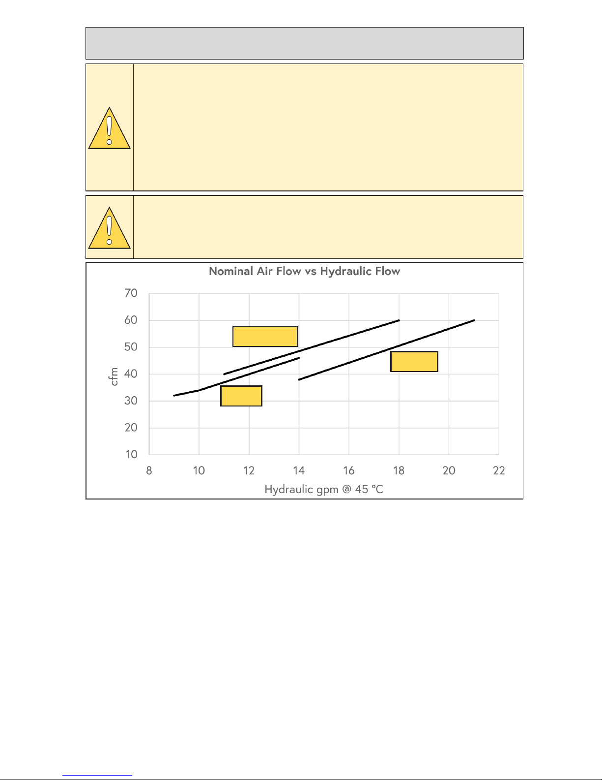
Figure 3 — cfm vs gpm
H60 HHP
H60
H40
VMAC is unable to provide hydraulic circuit designs or consult on
specific hydraulic installations. We recommend working with a local
hydraulic expert to design and/or install the hydraulic circuit that
will power the Hydraulic Driven Air Compressor system.
VMAC’s Hydraulic Driven Air Compressors are designed to be driven
by fixed displacement hydraulic pumps.
Hydraulic circuits using “pressure compensated” variable
displacement pumps must have a Closed Centre Manifold installed
at the Hydraulic Driven Air Compressor (see “Accessory Products
from VMAC” on page 83).
VMAC’s Hydraulic Driven Air Compressors are not compatible with
“load sensing” variable displacement hydraulic pumps.
VMAC - Vehicle Mounted Air Compressors
VMAC Technical Support: 888-241-2289
VMAC Knowledge Base: www.kb.vmacair.com
18
Hydraulic40
The system must maintain hydraulic flow between 9 gpm and 14 gpm (Figure 3).
Hydraulic60
The system must maintain hydraulic flow between 14 gpm and 21 gpm (Figure 3).
Hydraulic60 HHP
The system must maintain hydraulic flow between 12 gpm and 18 gpm (Figure 3).
The stated hydraulic flow rates are nominal values only and may change due to
variations in hydraulic system efficiency, load, and flow. Tests should be performed to
confirm that the desired cfm has been achieved.
If the Hydraulic Driven Air Compressor system is being installed into an existing
hydraulic circuit, ensure the circuit meets the requirements listed in this chapter.
See “Hydraulic Fluid and Line Sizing Recommendations” on page 19 for additional
information.
An independent hydraulic system is recommended to simplify
installation, operation, and troubleshooting of the Hydraulic Driven
Air Compressor system.
If this system is being installed in a shared hydraulic circuit, the use
of a shut off valve is advised.
VMAC - Vehicle Mounted Air Compressors
VMAC Technical Support: 888-241-2289
VMAC Knowledge Base: www.kb.vmacair.com
19
Hydraulic Fluid and Line Sizing
Recommendations
Use only premium quality mineral or synthetic anti wear hydraulic
fluid.
When selecting which hydraulic fluid to use, the decision should be based on the
lowest overnight temperature that the unit will be used in.
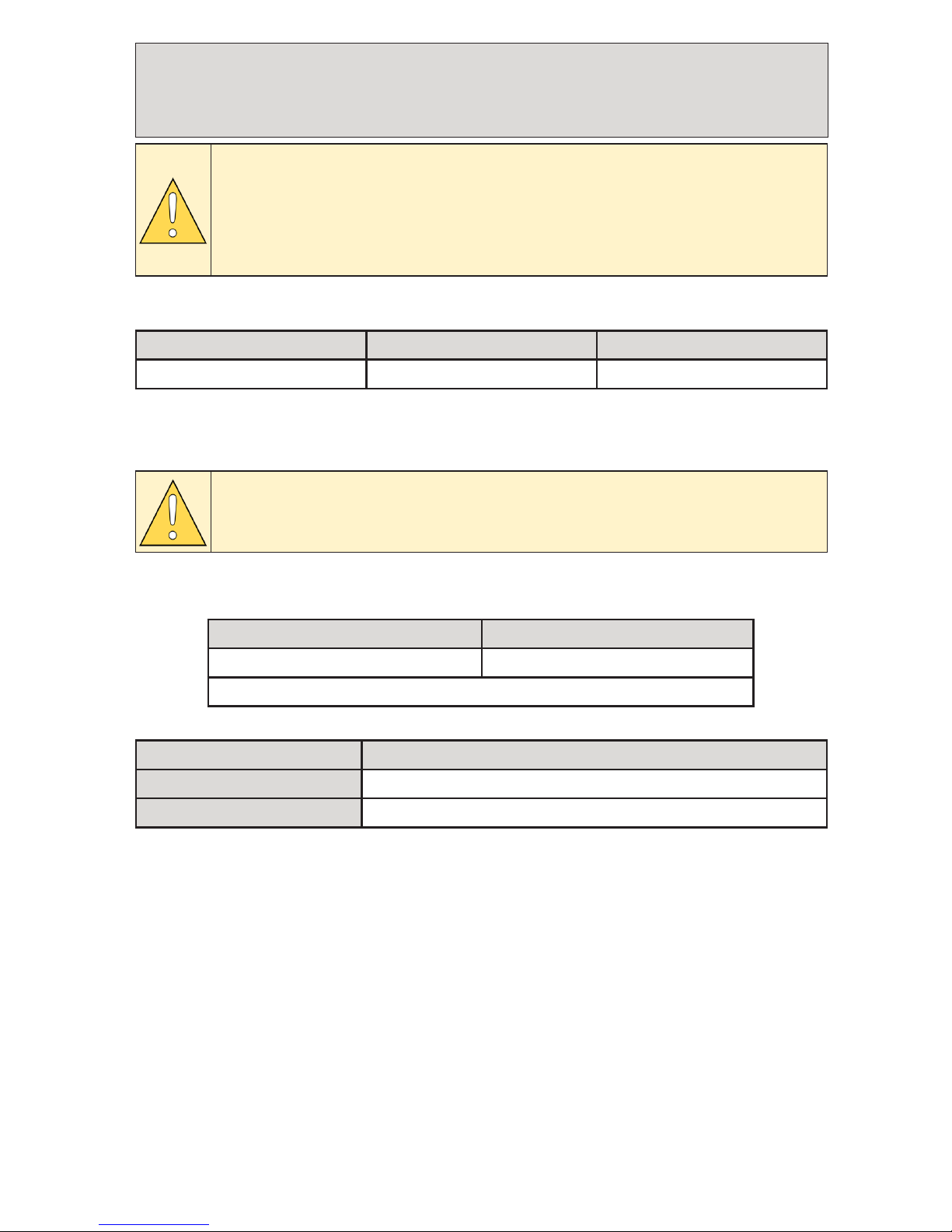
Hydraulic Fluid Type
Table 1 — Temperature reference chart
Extreme Cold Climate Cold Climate Temperate Climate
Below -4 °F (-19 °C) -3 °F — 32 °F ( -19 °C — 0 °C) Above 32 °F (0 °)
Cold Climate Temperate Climate
AW22 † AW32
† When possible change to AW32 (e.g. during summer months)
Table 2 — Hydraulic fluid chart
Climate / Temperature Reference Chart
VMAC is unable to provide hydraulic circuit designs or consult on
specific hydraulic installations. We recommend working with a local
hydraulic expert to design and/or install the hydraulic circuit that
will power the Hydraulic Driven Air Compressor system.
The following information is intended as a guideline only.
Mount Location Extreme Cold Climate
Tank and Suction Line Preheat
AW32
No Tank Preheat A seasonal hydraulic fluid change is recommended.
Table 3 — Hydraulic fluid recommendation for extreme cold climates
VMAC - Vehicle Mounted Air Compressors
VMAC Technical Support: 888-241-2289
VMAC Knowledge Base: www.kb.vmacair.com
20
Hydraulic Line Sizing
Industrial hydraulic system design guidelines generally call for the following
maximum fluid velocities, which are then used to select line sizes for any particular
gpm:
•
Supply 4 ft/sec.
•
Return 10 ft/sec.
•
Pressure 20 ft/sec.
The above guidelines are not considered comprehensive when working with mobile
hydraulic applications on prebuilt chassis due to the following factors:
•
Extreme start-up temperature variations.
•
Long supply lines.
•
Piggy-backing of motor case drain flow onto the main return line.
Hydraulic pump failure due to cavitation, and/or hydraulic motor
seal failure due to excess return line pressure, may occur if
the above considerations are ignored when line sizes are being
determined.
The following information provides specific line sizing recommendations for mobile
hydraulic system installations intended for use with VMAC’s Hydraulic Driven Air
Compressor systems. The dimensions provided indicate “inside diameter” (ID).
Supply Line Sizing
Failure to use the correct suction line size may result in hydraulic
pump cavitation leading to premature pump failure.
☐
In order to determine the appropriate supply line size, first identify the climate
that the system will be used in (Table 1), then select the corresponding line size
based off of the maximum gpm of the system (Table 4 or Table 5 starting on
page 21).
Special design considerations are required for hydraulic systems
operating in extreme cold climates.
VMAC recommends consulting with hydraulic experts experienced in
the design and installation of hydraulic circuits that will be used in
temperatures below -4 °F (-19 °C).
VMAC - Vehicle Mounted Air Compressors
VMAC Technical Support: 888-241-2289
VMAC Knowledge Base: www.kb.vmacair.com
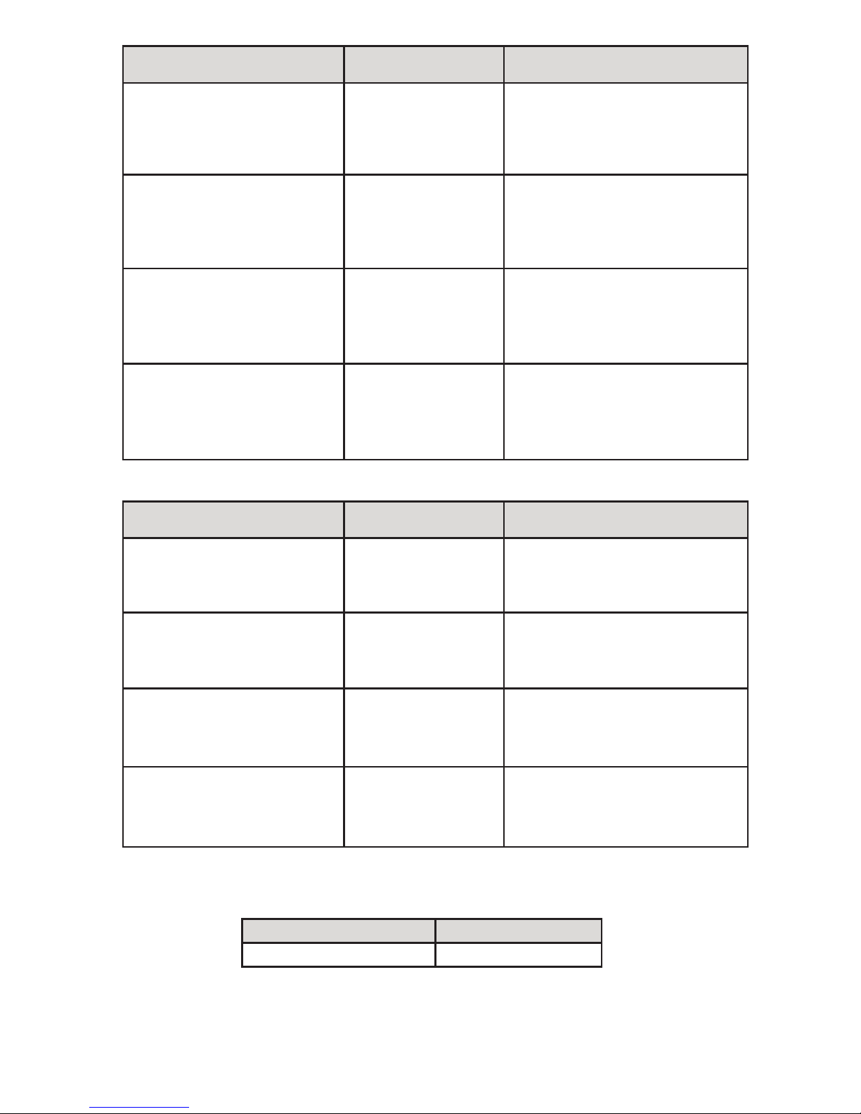
21
gpm during start up / warm up
Supply Line Size
AW 22
Supply Line Size
AW 32
Up to 8 gpm
1 in (up to 1 ft)
1 1/4 in (up to 2 1/2 ft)
1 1/2 in (up to 6 ft)
1 3/4 in (up to 9 ft)
2 in (above 9 ft)
1 1/4 in (up to 1 ft)
1 1/2 in (up to 2 1/2 ft)
1 3/4 in (up to 3 1/2 ft)
2 in (up to 8 ft)
2 1/2 in (above 8 ft)
12 gpm
1 1/4 in (up to 1 1/2 ft)
1 1/2 in (up to 4 ft)
1 3/4 in (up to 6 ft)
2 in (up to 12 ft)
2 1/2 in (above 12 ft)
1 1/2 in (up to 1 1/2 ft)
1 3/4 in (up to 2 1/2 ft)
2 in (up to 5 ft)
2 1/2 in (up to 13 ft)
3 in (above 13 ft)
16 gpm
1 1/2 in (up to 3 ft)
1 3/4 in (up to 4 1/2 ft)
2 in (up to 9 ft)
2 1/2 in (above 9 ft)
1 1/2 in (up to 1 ft)
1 3/4 in (up to 2 ft)
2 in (up to 4 ft)
2 1/2 in (up to 10 ft)
3 in (above 10 ft)
21 gpm
1 1/2 in (up to 2 ft)
1 3/4 in (up to 3 1/2 ft)
2 in (up to 7 ft)
2 1/2 in (above 7 ft)
1 1/2 in (up to 1 ft)
1 3/4 in (up to 1 1/2 ft)
2 in (up to 3 ft)
2 1/2 in (up to 8 ft)
3 in (above 8 ft)
Table 4 — Cold climate
gpm during start up / warm up
Supply Line Size
AW 22
Supply Line Size
AW 32
Up to 8 gpm
1 in (up to 4 ft)
1 1/4 in (up to 8 ft)
1 1/2 in (above 8 ft)
1 in (up to 1 1/2 ft)
1 1/4 in (up to 4 ft)
1 1/2 in (up to 9 ft)
1 3/4 in (above 9 ft)
12 gpm
1 1/4 in (up to 5 ft)
1 1/2 in (up to 11 ft)
1 3/4 in (above 11 ft)
1 1/4 in (up to 2 1/2 ft)
1 1/2 in (up to 6 ft)
1 3/4 in (up to 9 ft)
2 in (above 9 ft)
16 gpm
1 1/2 in (up to 9 ft)
1 3/4 in (up to 13 ft)
2 in (above 13 ft)
1 1/2 in (up to 4 ft)
1 3/4 in (up to 7 ft)
2 in (up to 14 ft)
2 1/2 in (above 14 ft)
21 gpm
1 1/2 in (up to 7 ft)
1 3/4 in (up to 11 ft)
2 in (above 11 ft)
1 1/2 in (up to 2 1/2 ft)
1 3/4 in (up to 5 ft)
2 in (up to 11 ft)
2 1/2 in (above 11 ft)
Table 5 — Temperate climate
Pressure Line Size Return Line Size
3/4 in 1 in
Table 6 — Pressure and return line size
Pressure and Return Line Sizing
VMAC - Vehicle Mounted Air Compressors
VMAC Technical Support: 888-241-2289
VMAC Knowledge Base: www.kb.vmacair.com
22
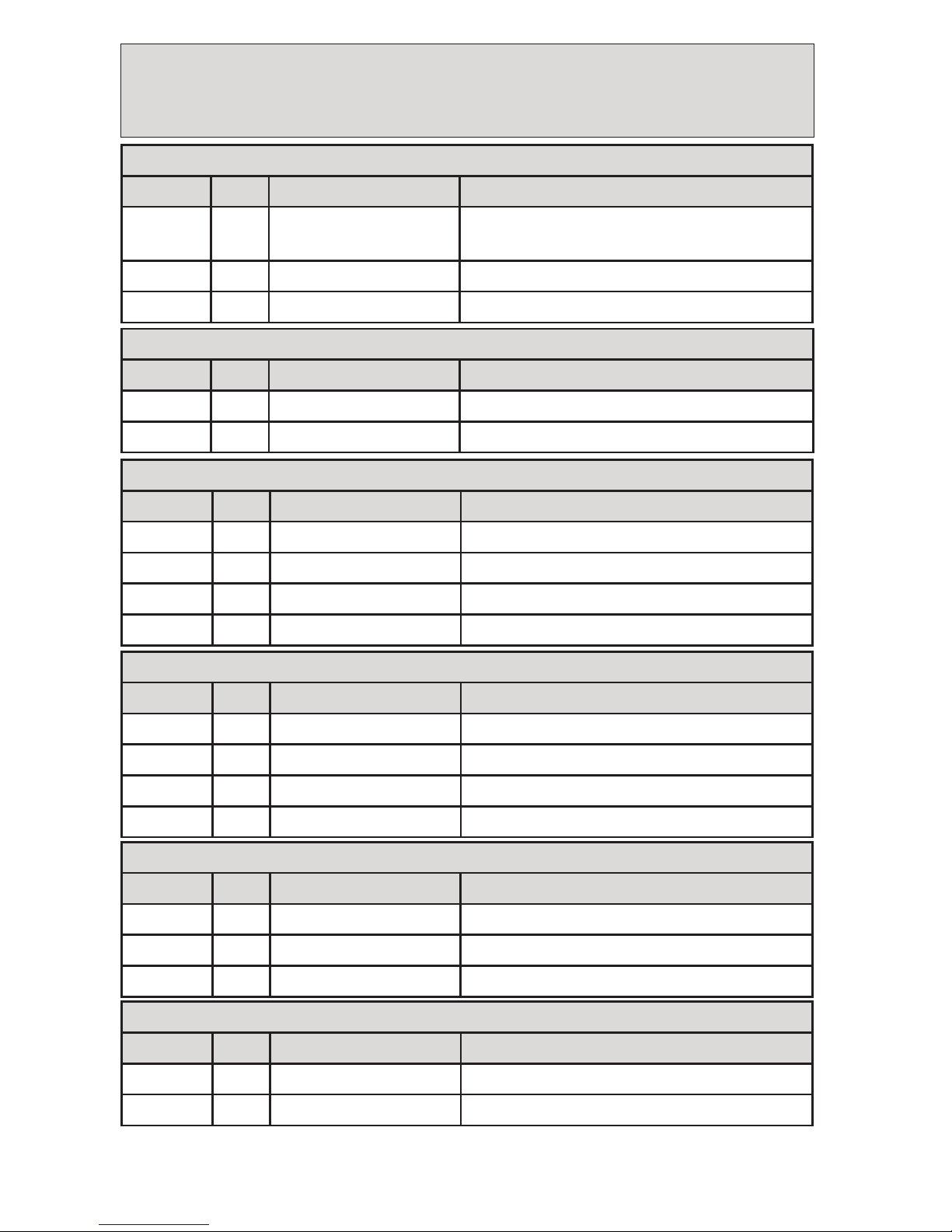
Hydraulic Driven Air Compressor Harness
Reference
Installer Interface
Colour Pin Function Notes
Purple A High Idle Output
Ground switching signal, use to supply
ground to relay or equivalent
Green B System Ground 0 Ω
Red C System Power
+
12 V (H400003: +24 V)
Fan Motor
Colour Pin Function Notes
Red A Relay Switched +12 V+12 V (H400003: +24 V)
Green B System Ground 0 Ω
Fan Relay
Colour Pin Function Notes
Red 85 System Power
+
12 V
Orange 86 Switched Ground Switched
Red 87 Relay Switched +12 V (To fan motor) +12 V (H400003: +24 V)
Red 30 System Power
+
12 V (H400003: +24 V)
Display Box
Colour Pin Function Notes
Red A Display +12 V
+
12 V
Green B Display Ground 0 Ω
White C CAN Hi CAN bus signal
Black D CAN Low CAN bus signal
System Pressure Sensor
Colour Pin Function Notes
Red –
+
5 V
+
5 V
Green – Pressure Signal
+
0.5 V – +4.5 V, 0 – 150 psi (ratiometric)
Black – Ground 0 Ω
Air Solenoid
Colour Pin Function Notes
Red 1
+
12 V Supply
+
12 V
Black 2 Switched Ground Switched
VMAC - Vehicle Mounted Air Compressors
VMAC Technical Support: 888-241-2289
VMAC Knowledge Base: www.kb.vmacair.com
23
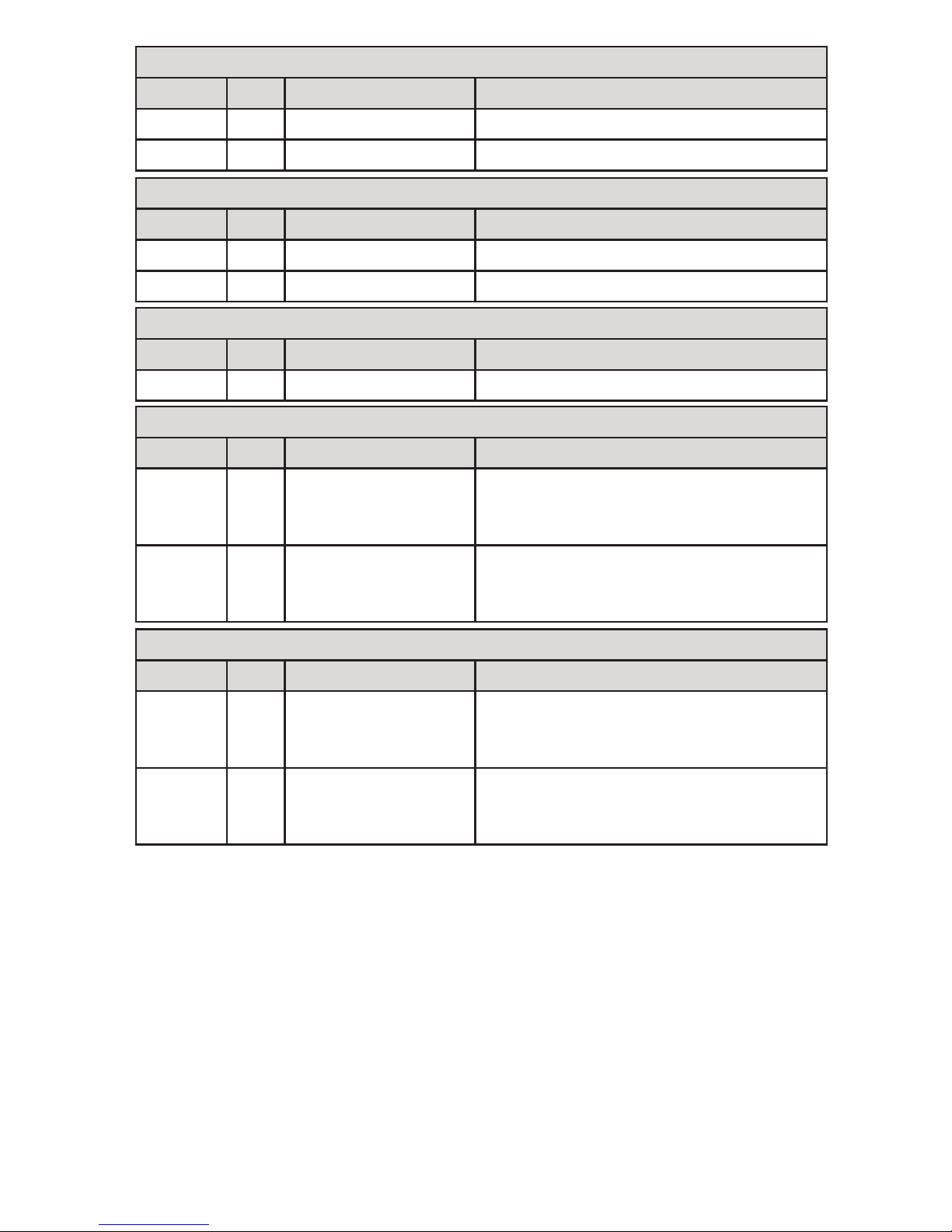
Remote Switch Wire
Colour Pin Function Notes
Yellow – Remote Enable Wire Ground wire to run compressor
Hydraulic Solenoid
Colour Pin Function Notes
Red A Switched Ground Switched
Red B
+
12 V Supply
+
12 V
Heater Solenoid (Cold Climate Kit P/N: A800070)
Colour Pin Function Notes
Blue A Switched Ground Switched
Blue B
+
12 V Supply
+
12 V
Compressor Temperature Probe
Colour Pin Function Notes
White A
Thermistor Signal
Voltage
Varies with temperature - see
thermistor resistance tables for further
diagnosis.
White B
Thermistor Signal
Voltage
Varies with temperature - see
thermistor resistance tables for further
diagnosis.
Hydraulic Temperature Probe
Colour Pin Function Notes
White A
Thermistor Signal
Voltage
Varies with temperature - see
thermistor resistance tables for further
diagnosis.
White B
Thermistor Signal
Voltage
Varies with temperature - see
thermistor resistance tables for further
diagnosis.
Table 7 — Harness reference chart
VMAC - Vehicle Mounted Air Compressors
VMAC Technical Support: 888-241-2289
VMAC Knowledge Base: www.kb.vmacair.com
24
Electrical Requirements (12 V dc Systems)
VMAC’s Hydraulic Driven Air Compressor systems require steady a 20 A at 12 V dc
(nominal) to operate. A 30 A fuse or circuit breaker is recommended.
To ensure an uninterrupted supply of power, the ground wire should be routed
either to the negative terminal of the battery or to a substantial, fully grounded
point on the vehicle chassis. Confirm the selected ground is good by using an
ohm meter to measure the resistance between the ground point and the negative
battery terminal. Resistance should be less than 1 Ω.
The power supplied to the unit should be ignition switched through a relay to
reduce the risk of battery drain when the engine is off. The main power should be
supplied directly from the positive terminal of the battery via a relay. Using a relay
allows the heavy gauge power wire to be routed directly and permits the use of a
light gauge wire (e.g. 18 AWG) between the relay and the control switch.
The information in this section is critical to ensure proper operation
of the system. Read these requirements prior to beginning the
installation.
Failure to adhere to these recommendations will cause the
Hydraulic Driven Air Compressor system to operate erratically.
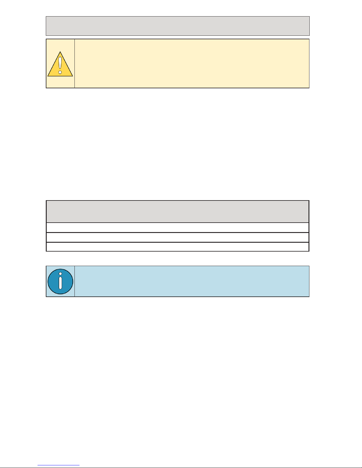
Wire Sizing Guide 12 V Systems
Combined length of power and ground wires Recommended wire gauge
Less than 10 ft (3 m) 12 AWG
Between 10 ft (3 m) and 18 ft (5.5 m) 10 AWG
18 ft (5.5 m) to a maximum of 35 ft (10.5 m) 8 AWG
Table 8 — Wire size table
VMAC does not recommend installing the system in a location that
would require a combined wire length greater than 35 ft (10.5 m).
VMAC - Vehicle Mounted Air Compressors
VMAC Technical Support: 888-241-2289
VMAC Knowledge Base: www.kb.vmacair.com
25
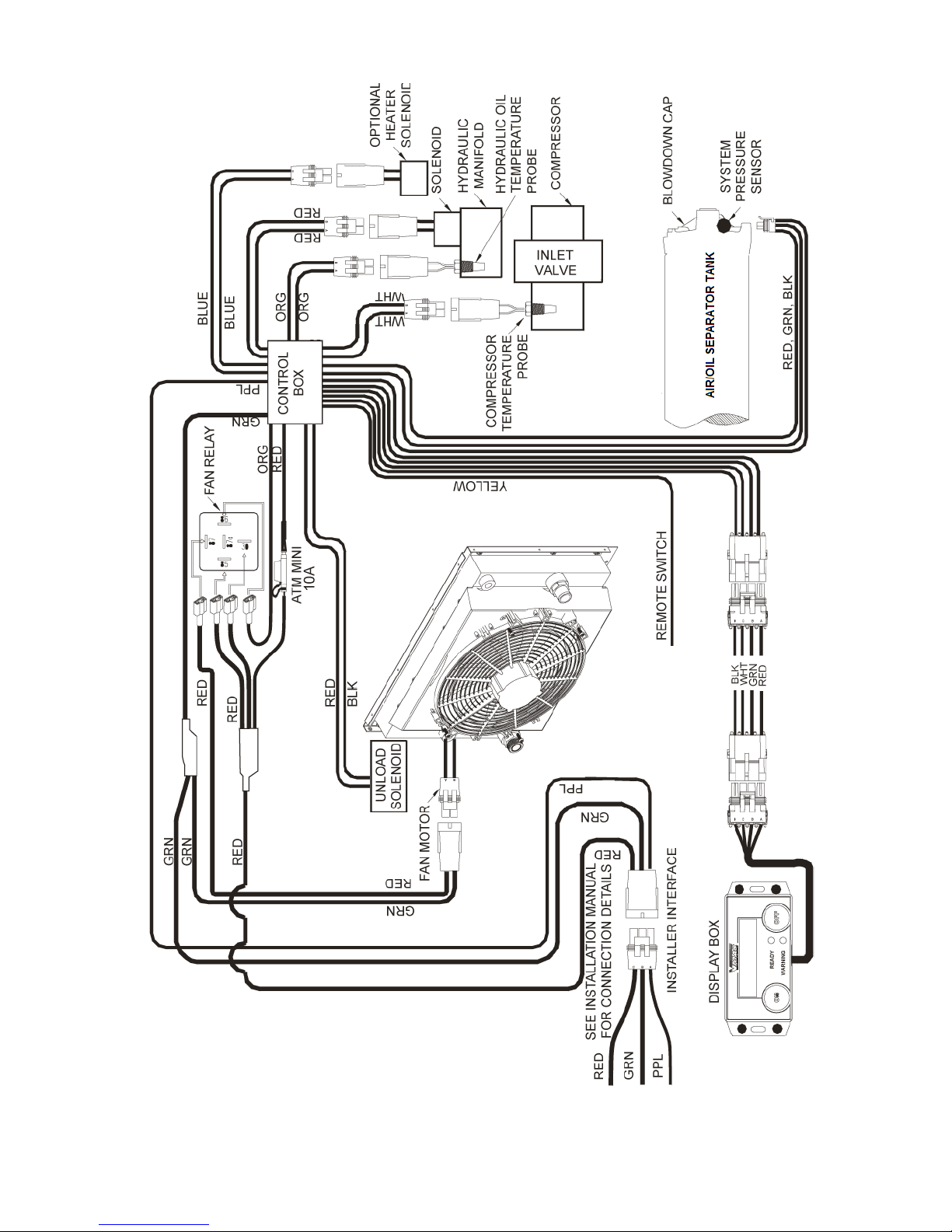
Electrical Schematic 12 V dc
Figure 4 — Electrical schematic 12 V dc
VMAC - Vehicle Mounted Air Compressors
VMAC Technical Support: 888-241-2289
VMAC Knowledge Base: www.kb.vmacair.com
26
Electrical Requirements (24 V dc Systems)
The information in this section is critical to ensure proper operation
of the system. Read these requirements prior to beginning the
installation.
Failure to adhere to these recommendations will cause the
Hydraulic Driven Air Compressor system to operate erratically.
Wire Sizing Guide 24 V Systems
Combined length of power and ground wires Recommended wire gauge
Less than 10 ft (3 m) 14 AWG
Between 10 ft (3 m) and 18 ft (5.5 m) 12 AWG
18 ft (5.5 m) to a maximum of 35 ft (10.5 m) 10 AWG
Table 9 — Wire size table
VMAC’s Hydraulic Driven Air Compressor systems require steady a 15 A at 24 V dc
(nominal) to operate. A 25 A fuse or circuit breaker is recommended.
To ensure an uninterrupted supply of power, the ground wire should be routed
either to the negative terminal of the battery or to a substantial, fully grounded
point on the vehicle chassis. Confirm the selected ground is good by using an
ohm meter to measure the resistance between the ground point and the negative
battery terminal. Resistance should be less than 1 Ω.
The power supplied to the unit should be ignition switched through a relay to
reduce the risk of battery drain when the engine is off. The main power should be
supplied directly from the positive terminal of the battery via a relay. Using a relay
allows the heavy gauge power wire to be routed directly and permits the use of a
light gauge wire (e.g. 18 AWG) between the relay and the control switch.
VMAC does not recommend installing the system in a location that
would require a combined wire length greater than 35 ft (10.5 m).
 Loading...