

Page 1
MAKING MODERN LIVING POSSIBLE
Operating Instructions
VLT® Soft Starter - MCD 500
Page 2

Contents MCD 500 Operating Instruction
Contents
1 Safety
1.1 Safety
2 Introduction
2.1.1 Feature List 7
2.1.2 Type Code 8
3 Installation
3.1 Mechanical Installation
3.2 Dimensions and Weights
4 Electrical Installation
4.1.1 Control Wiring 11
4.1.2 Control Terminals 11
4.1.3 Remote Inputs 11
4.1.4 Serial Communication 12
4.1.5 Earth Terminal 12
4.1.6 Power Terminations 12
5
5
7
9
9
10
11
4.2 Motor Connection
4.2.1 Testing the Installation 13
4.2.2 In-line Installation 14
4.2.2.1 In-line Installation, Internally Bypassed 14
4.2.2.2 In-line Installation, Non-bypassed 14
4.2.2.3 In-line Installation, Externally Bypassed 14
4.2.3 Inside Delta Installation 15
4.2.3.1 Inside Delta Installation, Internally Bypassed 15
4.2.3.2 Inside Delta Installation, Non-bypassed 15
4.2.3.3 Inside Delta Installation, Externally Bypassed 15
4.3 Current Ratings
4.3.1 In-line Connection (Bypassed) 17
4.3.2 AC-53 Rating for Bypassed Operation 17
4.3.3 In-line Connection (Non-bypassed/Continuous) 18
4.3.4 AC-53 Rating for Continuous Operation 18
4.3.5 Inside Delta Connection (Bypassed) 19
4.3.6 AC-53 Rating for Bypassed Operation 19
13
16
4.3.7 Inside Delta Connection (Non-bypassed/Continuous) 20
4.3.8 AC-53 Rating for Continuous Operation 20
4.4 Minimum and Maximum Current Settings
4.5 Bypass Contactor
4.6 Main Contactor
MG17K402 - VLT® is a registered Danfoss trademark 1
21
21
21
Page 3
Contents MCD 500 Operating Instruction
4.7 Circuit Breaker
4.8 Power Factor Correction
4.9 Fuses
4.9.2 Bussman Fuses - Square Body (170M) 23
4.9.3 Bussman Fuses - British Style (BS88) 24
4.9.4 Ferraz Fuses - HSJ 25
4.9.5 Ferraz Fuses - North American Style (PSC 690) 26
4.9.6 UL Tested Fuses - Short Circuit Ratings 27
4.10 Schematic Diagrams
4.10.1 Internally Bypassed Models 28
4.10.2 Non-bypassed Models 29
5 Application Examples
5.1 Motor Overload Protection
5.2 AAC Adaptive Acceleration Control
5.3 Starting Modes
5.3.1 Constant Current 31
5.3.2 Current Ramp 31
21
22
22
28
30
30
30
31
5.3.3 AAC Adaptive Acceleration Control 31
5.3.4 Kickstart 32
5.4 Stopping Modes
5.4.1 Coast to Stop 32
5.4.2 TVR Soft Stop 32
5.4.3 AAC Adaptive Acceleration Control 33
5.4.4 Brake 33
5.5 Jog Operation
5.6 Inside Delta Operation
5.7 Typical Start Currents
5.8 Installation with Main Contactor
5.9 Installation with Bypass Contactor
5.10 Emergency Run Operation
5.11 Auxiliary Trip Circuit
5.12 DC Brake with External Zero Speed Sensor
5.13 Soft Braking
5.14 Two Speed Motor
32
34
35
35
38
39
40
41
42
42
44
6 Operation
6.1 Operation and LCP
6.1.1 Operating Modes 46
6.2 Remote Mounted LCP
6.2.1 Synchronising the LCP and the Starter 47
2 MG17K402 - VLT® is a registered Danfoss trademark
46
46
46
Page 4
Contents MCD 500 Operating Instruction
6.3 Welcome Screen
6.4 Control Methods
6.5 Local Control Buttons
6.6 Displays
6.6.1 Temperature Monitoring Screen (S1) 48
6.6.2 Programmable Screen (S2) 48
6.6.3 Average Current (S3) 48
6.6.4 Current Monitoring Screen (S4) 49
6.6.5 Frequency Monitoring Screen (S5) 49
6.6.6 Motor Power Screen (S6) 49
6.6.7 Last Start Information (S7) 49
6.6.8 Date and Time (S8) 49
6.6.9 SCR Conduction Bargraph 49
6.6.10 Performance Graphs 49
7 Programming
7.1 Access Control
7.2 Quick Menu
47
47
48
48
50
50
51
7.2.1 Quick Setup 51
7.2.2 Application Setups 52
7.2.3 Loggings 53
7.3 Main Menu
7.3.1 Parameters 53
7.3.2 Parameter Shortcut 53
7.3.3 Parameter List 54
7.4 Primary Motor Settings
7.4.1 Brake 56
7.5 Protection
7.5.1 Current Imbalance 56
7.5.2 Undercurrent 57
7.5.3 Instantaneous Overcurrent 57
7.5.4 Frequency Trip 57
7.6 Inputs
7.7 Outputs
7.7.1 Relay A Delays 59
53
55
56
58
59
7.7.2 Relays B and C 59
7.7.3 Low Current Flag and High Current Flag 60
7.7.4 Motor Temperature Flag 60
7.7.5 Analog Output A 60
7.8 Start/Stop Timers
7.9 Auto-Reset
MG17K402 - VLT® is a registered Danfoss trademark 3
60
61
Page 5
Contents MCD 500 Operating Instruction
7.9.1 Auto-Reset Delay 61
7.10 Secondary Motor Set
7.11 Display
7.11.1 User Programmable Screen 63
7.11.2 Performance Graphs 64
7.12 Restricted Parameters
7.13 Protection Action
7.14 Factory Parameters
8 Tools
8.1 Set Date and Time
8.2 Load/Save Settings
8.3 Reset Thermal Model
8.4 Protection Simulation
8.5 Output Signal Simulation
8.6 Digital I/O State
8.7 Temp Sensors State
8.8 Alarm Log
8.8.1 Trip Log 69
61
63
65
66
66
67
67
67
67
68
68
68
68
69
8.8.2 Event Log 69
8.8.3 Counters 69
9 Troubleshooting
9.1 Trip Messages
9.2 General Faults
10 Specifications
10.1 Accessories
10.1.1 LCP Remote Mounting Kit 76
10.1.2 Communication Modules 76
10.1.3 PC Software 77
10.1.4 Finger Guard Kit 77
10.1.5 Surge Protection Kit (Lightning Protection) 77
11 Bus Bar Adjustment Procedure (MCD5-0360C - MCD5-1600C)
70
70
73
75
76
78
4 MG17K402 - VLT® is a registered Danfoss trademark
Page 6
Safety MCD 500 Operating Instruction
1 Safety
1.1 Safety
When reading this manual you will come across different
symbols that require special attention. The symbols used
are the following:
NOTE
Indicates something to be noted by the reader
CAUTION
Indicates a general warning
WARNING
Indicates a high voltage warning
The examples and diagrams in this manual are included
solely for illustrative purposes. The information contained
in this manual is subject to change at any time and
without prior notice. In no event will responsibility or
liability be accepted for direct, indirect or consequential
damages resulting from the use or application of this
equipment.
NOTE
Before changing any parameter settings, ensure that the
current parameter set is saved to an internal file. Refer to
MCD 500 Operating Instructions, MG.17.KX.YY, for more
information.
WARNING
WARNING - ELECTRICAL SHOCK HAZARD
MCD 500 soft starters contain dangerous voltages when
connected to mains voltage. Only a competent electrician
should carry out the electrical installation. Improper installation of the motor or the soft starter may cause
equipment failure, serious injury or death. Follow this
manual and local electrical safety codes.
Models MCD5-0360C - MCD5-1600C: The bus bar and
heatsink are live while the unit is operating (starting,
running or stopping). If the starter is installed without a
main contactor, the bus bar and heatsink are live
whenever mains voltage is connected (including when the
starter is ready or tripped).
WARNING
Disconnect the soft starter from mains voltage before
carrying out repair work.
It is the responsibility of the user or person installing the
soft starter to provide proper grounding and branch circuit
protection according to local electrical safety codes.
Do not connect power factor correction capacitors to the
output of MCD 500 soft starters. If static power factor
correction is employed, it must be connected to the supply
side of the soft starter.
MCD5-0021B - MCD5-0105B: After transportation,
mechanical shock or rough handling there is possibility
that the bypass contactor may have latched into the on
state. To prevent the possibility of the motor starting
immediately, on first commissioning or operation after
transportation, always ensure that the control supply is
applied before the power, so that the contactor state is
initialised.
WARNING
Safety of Personnel
The soft starter is not a safety device and does not provide
electrical isolation or disconnection from the supply.
If isolation is required, the soft starter must be
•
installed with a main contactor
The start and stop functions of the soft starter
•
must not be relied upon for personnel safety. A
motor may start or stop unexpectedly if faults
occur in the mains supply, the motor connection,
or the electronics of the soft starter.
To provide machine or personnel safety, the isolation
device must be controlled through an external safety
system.
In Auto On mode, the motor can be stopped using digital
or bus commands while the soft starter is connected to
mains.
CAUTION
These stop functions are not sufficient to avoid unintended
start.
A motor that has been stopped may start if faults occur in
the electronics of the soft starter, or a temporary fault in
the supply mains or the motor connection ceases.
1 1
CAUTION
Use the auto-start feature with caution. Read all the notes
related to auto-start before operation.
MG17K402 - VLT® is a registered Danfoss trademark 5
Page 7
Safety MCD 500 Operating Instruction
11
Table 1.1
Equipment containing electrical
components may not be disposed of
together with domestic waste.
It must be collected separately as
electrical and electronic waste
according to local and currently valid
legislation.
6 MG17K402 - VLT® is a registered Danfoss trademark
Page 8

Introduction MCD 500 Operating Instruction
2 Introduction
The MCD 500 is an advanced digital soft start solution for
motors from 7 kW to 800 kW. MCD 500 soft starters
provide a complete range of motor and system protection
features and have been designed for reliable performance
in the most demanding installation situations.
2.1.1 Feature List
Models for all connection requirements
21 A to 1600 A (in-line connection)
•
In-line or inside delta connection
•
Internally bypassed up to 215 A
•
Mains voltage: 200 - 525 VAC or 380 - 690 VAC
•
Control voltage: 24 VAC/VDC, 110 - 120 VAC or
•
220 - 240 VAC
User-friendly LCP
Loggings
•
Real-time graphs
•
SCR conduction bar graph
•
Tools
Application setups
•
Date and time stamped event log with 99 entries
•
8 most recent trips
•
Counters
•
Protection simulation
•
Output signal simulation
•
Inputs and Outputs
Local or remote control input options
•
(3 x fixed 1 x programmable)
Relay outputs (3 x programmable)
•
Analog programmable output
•
24 VDC 200 mA supply output
•
Start and run modes
AAC - Adaptive Acceleration Control
•
Constant current
•
Current ramp
•
Kickstart
•
Jog
•
Emergency run operation
•
Stop modes
AAC - Adaptive Acceleration Control
•
Timed voltage ramp soft stop
•
DC brake
•
Soft brake
•
Emergency stop
•
Other features
Auto start/stop timer
•
Second order thermal model
•
Battery backup of clock and thermal model
•
Optional DeviceNet, Modbus or Profibus
•
communication modules
Comprehensive protection
Wiring/Connection/Supply
•
- Motor connection
- Phase sequence
- Power loss
- Individual phase loss
- Mains frequency
Current
•
- Excess start time
- Current imbalance
- Undercurrent
- Instantaneous overcurrent
Thermal
•
- Motor thermistor
- Motor overload
- Bypass relay overload
- Heatsink temperature
Communication
•
- Network comms
- Starter comms
External
•
- Input trip
Starter
•
- Individual shorted SCR
- Battery/Clock
2 2
MG17K402 - VLT® is a registered Danfoss trademark 7
Page 9
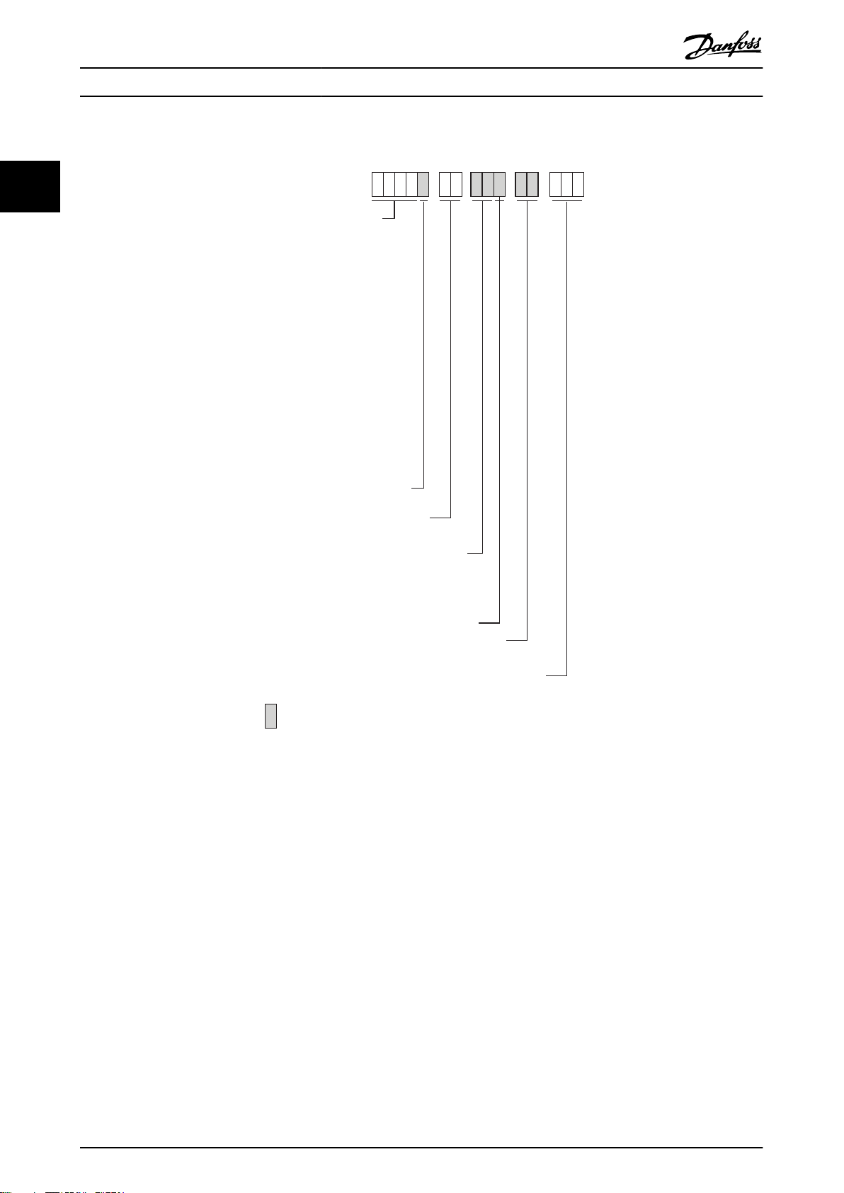
MCD 5
- - - -
Current rating
0021 = 21 A, AC53b 3-30:330
0037 = 37 A, AC53b 3-30:330
0043 = 43 A, AC53b 3-30:330
0053 = 53 A, AC53b 3-30:330
0068 = 68 A, AC53b 3-30:570
0084 = 84 A, AC53b 3-30:570
0089 = 89 A, AC53b 3-30:570
0105 = 105 A, AC53b 3-30:570
0131 = 131 A, AC53b 3-30:570
0141 = 141 A, AC53b 3-30:570
0195 = 195 A, AC53b 3-30:570
0215 = 215 A, AC53b 3-30:570
0245 = 245 A, AC53a 3-30:50-6
0360 = 360 A, AC53a 3-30:50-6
0380 = 380 A, AC53a 3-30:50-6
0428 = 428 A, AC53a 3-30:50-6
0595 = 595 A, AC53a 3-30:50-6
0619 = 619 A, AC53a 3-30:50-6
0790 = 790 A, AC53a 3-30:50-6
0927 = 927 A,AC53a 3-30:50-6
1200 = 1200 A, AC53a 3-30:50-6
1410 = 1410 A, AC53a 3-30:50-6
1600 = 1600 A, AC53a 3-30:50-6
Mains voltage
T5 = 200 - 525 VAC
T7 = 380 - 690 VAC
IP rating
00 = IP00
20 = IP20
Control voltage
CV1 = 24 VAC/VDC
CV2 = 110-120 VAC or 220-240 VAC
B = Bypassed
C = Non-bypassed
Frame size
G1 = 0021 ~ 0105 A
G2 = 0131 ~ 0215 A
G3 = 0245 A
G4 = 0360 A ~ 0927 A
G5 = 1200 A ~ 1600 A
Not used
= Not selectable
177HA382.11
Introduction MCD 500 Operating Instruction
2.1.2 Type Code
22
Illustration 2.1
8 MG17K402 - VLT® is a registered Danfoss trademark
Page 10
Installation MCD 500 Operating Instruction
3 Installation
3.1 Mechanical Installation
3
3
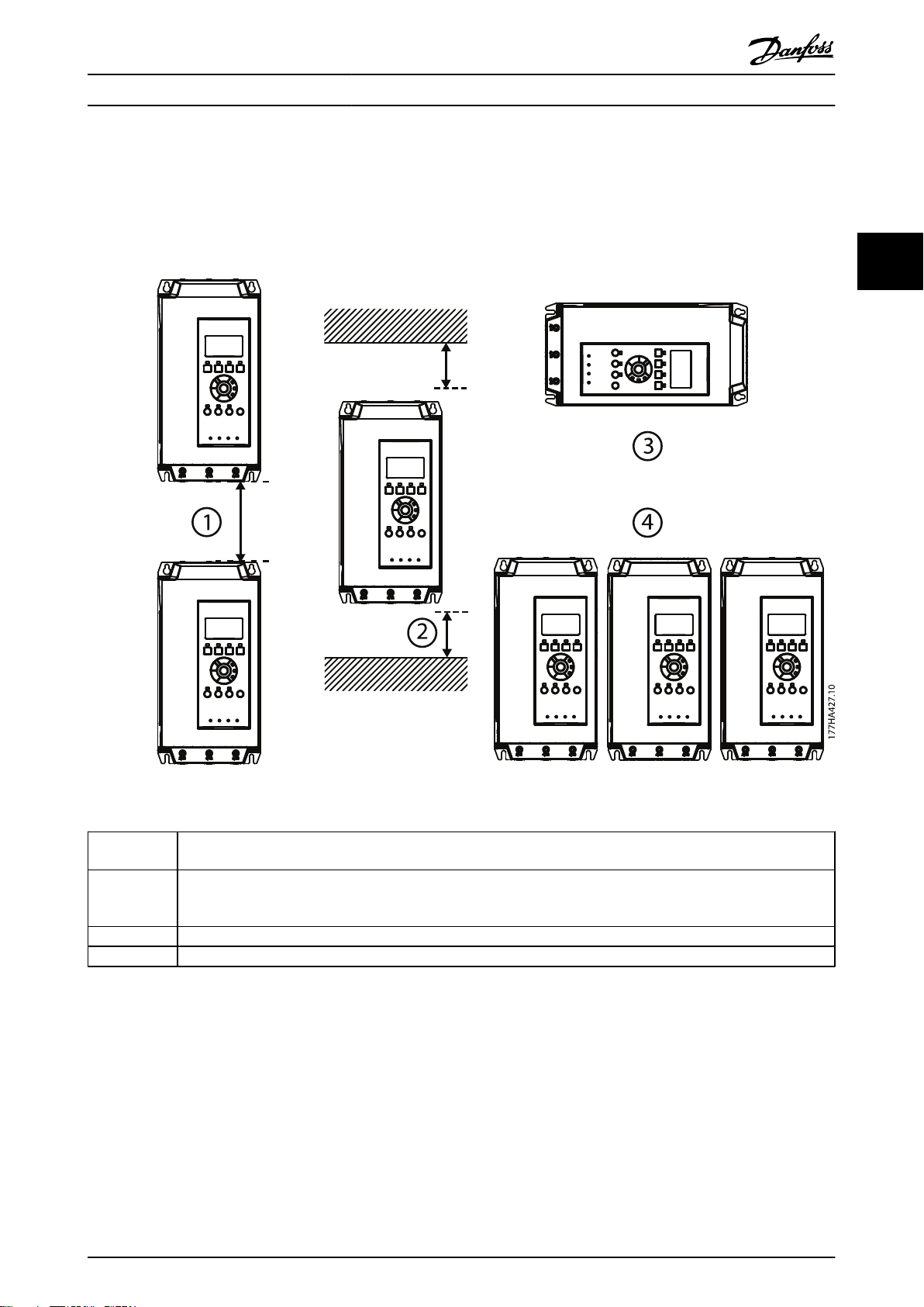
Illustration 3.1
1
2 MCD5-0021B - MCD5-0215B: Allow 50 mm (1.97 inches) between the soft starter and solid surfaces.
3 The soft starter may be mounted on its side. Derate the soft starter's rated current by 15%.
4 Soft starters may be mounted side by side with clearance of 50 mm (1.97 inches) on both sides.
Table 3.1
MCD5-0021B - MCD5-0245C: Allow 100 mm (3.94 inches) between soft starters.
MCD5-0360C - MCD5-1600C: Allow 200 mm (7.88 inches) between soft starters.
MCD5-0245C: Allow 100 mm (3.94 inches) between the soft starter and solid surfaces.
MCD5-0360C - MCD5-1600C: Allow 200 mm (7.88 inches) between the soft starter and solid surfaces.
MG17K402 - VLT® is a registered Danfoss trademark 9
Page 11
177HA514.10
3
Installation MCD 500 Operating Instruction
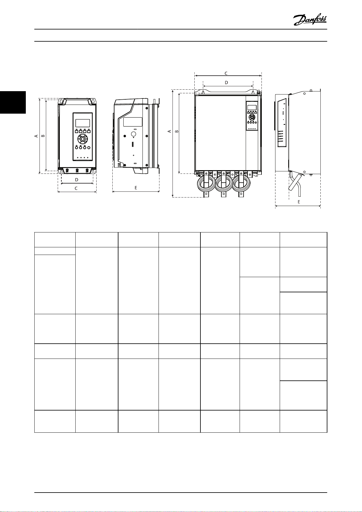
3.2 Dimensions and Weights
Illustration 3.2
Model A mm
MCD5-0021B
MCD5-0037B
MCD5-0043B
MCD5-0053B
MCD5-0068B
MCD5-0084B
MCD5-0089B
MCD5-0105B
MCD5-0131B
MCD5-0141B
MCD5-0195B
MCD5-0215B
MCD5-0245C 460
MCD5-0360C
MCD5-0380C
MCD5-0428C
MCD5-0595C
MCD5-0619C
MCD5-0790C
MCD5-0927C
MCD5-1200C
MCD5-1410C
MCD5-1600C
(11.6)
(inches)
295
438
(17.2)
(18.1)
689
(27.1)
856
(33.7)
B mm
(inches)
278
(10.9)
380
(15.0)
400
(15.0)
522
(20.5)
727
(28.6)
C mm
(inches)
150
(5.9)
275
(10.8)
390
(15.4)
430
(16.9)
585
(23.0)
D mm
(inches)
124
(4.9)
248
(9.8)
320
(12.6)
320
(12.6)
500
(19.7)
E mm
(inches)
183
(7.2)
213
(8.14)
250
(9.8)
279
(11.0)
300.2
(11.8)
364
(14.3)
Weight kg
(lbs)
4.2
(9.3)
4.5
(9.9)
4.9
(10.8)
14.9
(32.8)
23.9
(52.7)
35
(77.2)
45
(99.2)
120
(264.6)
Table 3.2
10 MG17K402 - VLT® is a registered Danfoss trademark
Page 12
177HA504.10
Start/stop
Reset
Start
Stop
Reset
Start
Stop
Reset
15
16
17
18
25
18
15
16
17
18
25
18
15
16
17
18
25
18
2
3
1
Electrical Installation MCD 500 Operating Instruction
4 Electrical Installation
To maintain SELV, all connections made to the control
4.1 Electrical Installation
4.1.1 Control Wiring
The soft starter can be controlled in three ways
using the buttons on the LCP
•
via remote inputs
•
via a serial communication link
•
The MCD 500 will always respond to a local start or stop
command (via the [Hand On] and [Off] buttons on the
LCP). Pressing the [Auto On] button selects remote control
(the MCD 500 will accept commands from the remote
inputs). In remote mode, the Auto On LED will be on. In
local mode, the Hand On LED will be on if the MCD 500 is
starting or running and the Off LED will be on if the MCD
500 is stopped or stopping.
terminals must be PELV (eg. thermistor must be reinforced/
double insulated from motor).
NOTE
SELV offers protection by way of extra low voltage.
Protection against electric shock is ensured when the
electrical supply is of the SELV type and the installation is
made as described in local/national regulations on SELV
supplies.
NOTE
Galvanic (ensured) isolation is obtained by fulfilling
requirements for higher isolation and by providing the
relevant creepages/clearance distances. These requirements
are described in the IEC61140 standard.
The components that make up the electrical isolation also
comply with the requirements for higher isolation and the
relevant test as described in IEC61140.
4 4
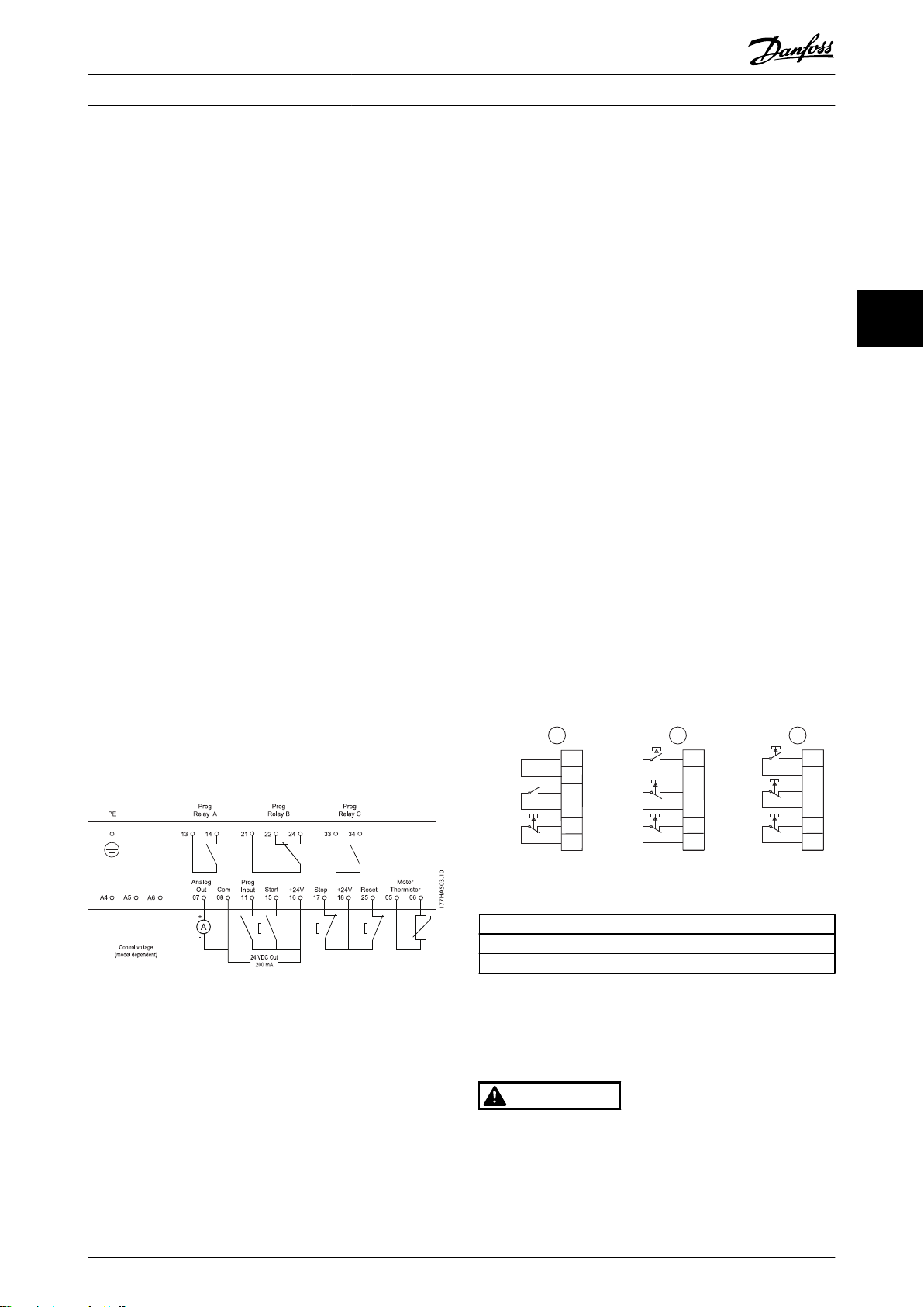
Control Terminals
4.1.2
Control terminations use 2.5 mm2 plug-in terminal blocks.
Different models require control voltage to different
terminals:
CV1 (24 VAC/VDC): A5, A6
CV2 (110 - 120 VAC): A5, A6
CV2 (220 - 240 VAC): A4, A6
Illustration 4.1
NOTE
Do not short terminals 05, 06 without using a thermistor.
4.1.3 Remote Inputs
The MCD 500 has three fixed inputs for remote control.
These inputs should be controlled by contacts rated for
low voltage, low current operation (gold flash or similar).
Illustration 4.2
1 Two-wire control
2 Three-wire control
3 Four-wire control
Table 4.1
The reset input can be normally open or normally closed.
Use 3-8 Remote Reset Logic to select the configuration.
All control terminals and relay terminals comply with SELV
(Protective Extra Low Voltage). This protection does not
apply to grounded Delta leg above 400 V.
MG17K402 - VLT® is a registered Danfoss trademark 11
CAUTION
Do not apply voltage to the control input terminals. These
are active 24 VDC inputs and must be controlled with
potential free contacts.
Cables to the control inputs must be segregated from
mains voltage and motor cabling
Page 13
Electrical Installation MCD 500 Operating Instruction
4.1.4 Serial Communication
Serial communication is always enabled in local control
mode, and can be enabled or disabled in remote control
mode (see 3-2 Comms in Remote).
4.1.5 Earth Terminal
Earth terminals are located at the back of the soft starter.
44
MCD5-0021B - MCD5-0105B have one terminal, on the input side.
•
MCD5-0131B - MCD5-1600C have two terminals, one on the input side and one on the output side.
•
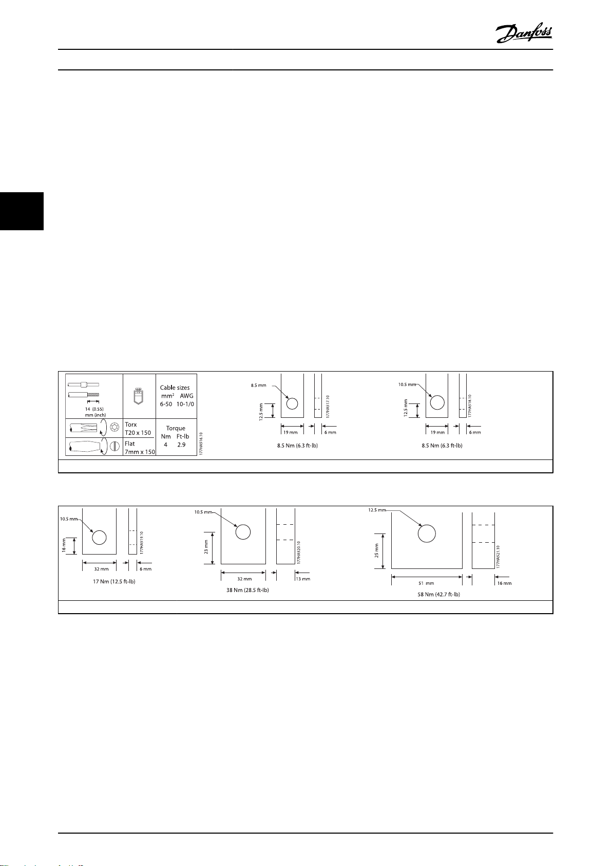
4.1.6 Power Terminations
Use only copper stranded or solid conductors, rated for 75° C.
NOTE
Some units are aluminium bus bars. When connecting power terminations, we recommend cleaning the surface contact
area thoroughly (using an emery or stainless steel brush) and using an appropriate jointing compound to prevent corrosion.
Table 4.2
Table 4.3
MCD5-0021B - MCD5-0105B MCD5-0131B MCD5-0141B - MCD5-0215B
MCD5-0245C
MCD5-0360C - MCD50927C MCD5-1200C - MCD5-1600C
12 MG17K402 - VLT® is a registered Danfoss trademark
Page 14
177HA542.11
Electrical Installation MCD 500 Operating Instruction
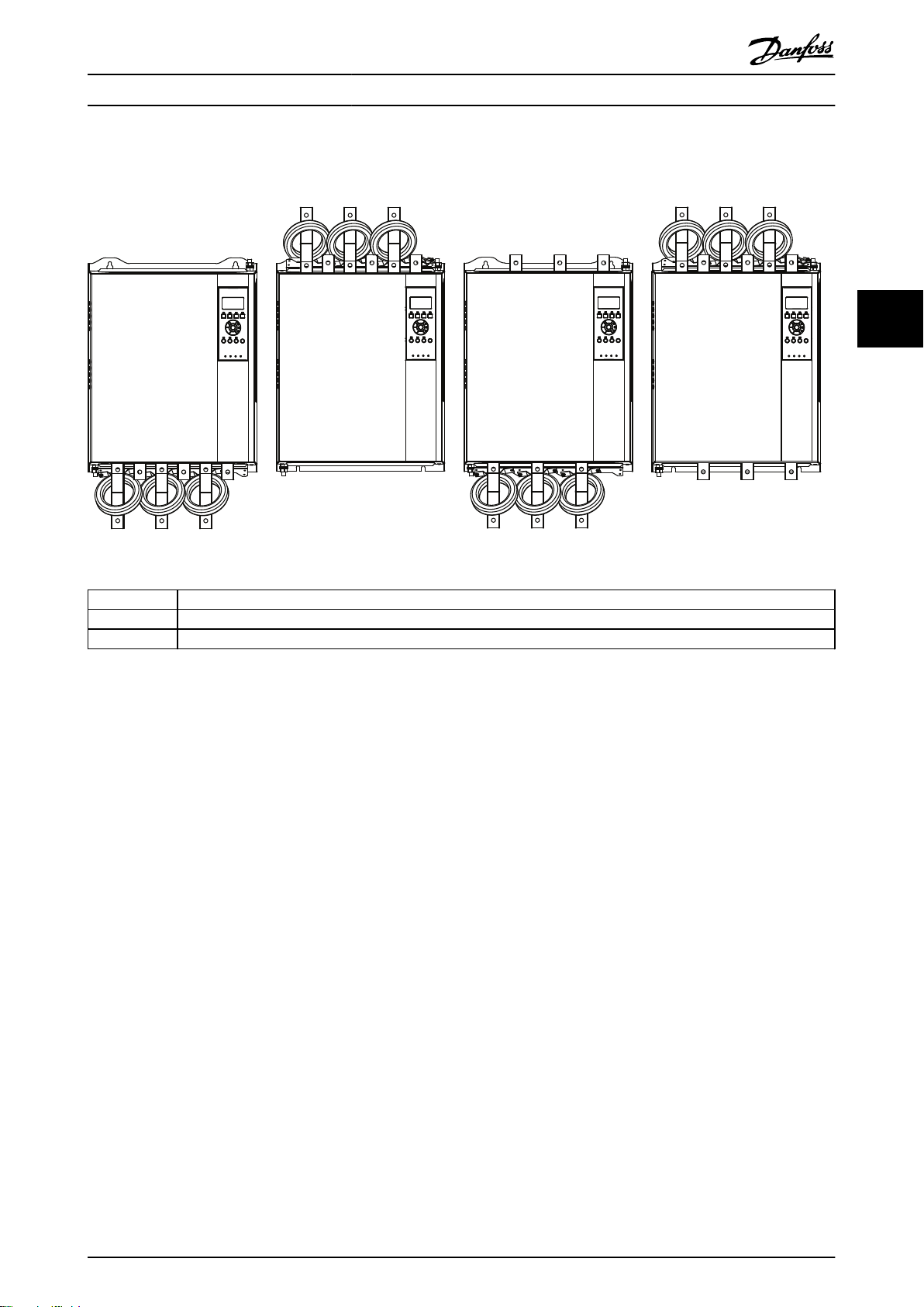
The bus bars on models MCD5-0360C - MCD5-1600C can be adjusted for top or bottom input and output as required. For
step-by-step instructions on adjusting the bus bars, refer to the supplied insert.
Illustration 4.3
4 4
I/O Input/Output
I Input
O Output
Table 4.4
4.2
Motor Connection
MCD 500 soft starters can be connected to the motor inline or inside delta (also called three-wire and six-wire
connection). The MCD 500 will automatically detect the
motor connection and perform the necessary calculations
internally, so it is only necessary to program the motor full
load current (1-1 Motor FLC).
NOTE
For personnel safety, the power terminals on models up to
MCD5-0105B are protected by snap-off tabs. When using
large cables, it may be necessary to break off these tabs.
Models which are internally bypassed do not require an
external bypass contactor.
4.2.1 Testing the Installation
The minimum motor FLC for test purposes is 2% of the
soft starter's minimum FLC (see 4.4 Minimum and Maximum
Current Settings).
NOTE
When testing the soft starter with a small motor, set 1-1
Motor FLC to the minimum allowable value.
The MCD 500 can be connected to a small motor for
testing. During this test, the soft starter's control input and
relay output protection settings can be tested. This test
mode is not suitable for testing soft starting or soft
stopping performance.
MG17K402 - VLT® is a registered Danfoss trademark 13
Page 15
177HA430.11
M
3
6/T3
2/T1
5/L3
3/L2
1/L1
13
14
4/T2
E
KM1
KM1 F1
177HA429.11
6/T3
2/T1
5/L3
3/L2
1/L1
13
14
4/T2
E
KM1
KM1
F1
M
3
177HA617.10
M
3
F1
6/T3
2/T1
5/L3
3/L2
1/L1
13
14
4/T2
E
KM1
KM1
T1B
T2B
T3B
KM2
34
33
KM2
Electrical Installation MCD 500 Operating Instruction
4.2.2 In-line Installation
programmable output configured to Run (see parameters
4.1 thorugh 4.9).
4.2.2.1 In-line Installation, Internally
Bypassed
NOTE
The bypass terminals on MCD5-0245C are T1B, T2B, T3B.
The bypass terminals on MCD5-0360C ~ MCD5-1600C are
L1B, L2B, L3B.
NOTE
The fuses can be installed on the input side if required.
44
Illustration 4.4
KM1 Main contactor (optional)
F1 Fuses (optional)
Table 4.5
4.2.2.2
In-line Installation, Non-bypassed
KM1 Main contactor
KM2 Bypass contactor (external)
F1 Semiconductor fuses (optional)
Table 4.7
Illustration 4.5
KM1 Main contactor (optional)
F1 Fuses (optional)
Illustration 4.6 MCD5-0245C
Table 4.6
4.2.2.3
In-line Installation, Externally
Bypassed
Non-bypassed models have dedicated bypass terminals,
which allow the soft starter to continue providing
protection and monitoring functions even when bypassed
via external contactor. The bypass contactor must be
connected to the bypass terminals and controlled by a
14 MG17K402 - VLT® is a registered Danfoss trademark
Page 16
177HA431.11
M
3
F1
6/T3
2/T1
5/L3
3/L2
1/L1
13
14
4/T2
E
KM1
KM1
L1B
L2B
L3B
KM2
34
33
KM2
177HA500.11
M
3
6/T3
2/T1
5/L3
3/L2
1/L1
13
14
4/T2
KM1
KM1 F1
U1(1) U2(4)
V1(2)
V2(5)
W1(3) W2(6)
L2B
L1B
L3B
E
Electrical Installation MCD 500 Operating Instruction
4.2.3.1 Inside Delta Installation, Internally
Bypassed
4 4
Illustration 4.7 MCD5-0360C ~ MCD5-1600C
KM1 Main contactor
KM2 Bypass contactor (external)
F1 Semiconductor fuses (optional)
Table 4.8
Inside Delta Installation
4.2.3
CAUTION
When connecting the MCD 500 in inside delta configuration, always install a main contactor or shunt trip circuit
breaker.
NOTE
When connecting in inside delta, enter the motor full load
current (FLC) for 1-1 Motor FLC. MCD 500 software
calculates inside delta currents from this. 15-7 Motor
Connection is set to Auto detect as default and can be set
to force the soft starter inside delta or in-line.
Illustration 4.8
KM1 Main contactor
F1 Fuses (optional)
Table 4.9
4.2.3.2
Inside Delta Installation, Nonbypassed
Illustration 4.9
KM1 Main contactor
F1 Fuses (optional)
Table 4.10
4.2.3.3
Inside Delta Installation, Externally
Bypassed
Non-bypassed models have dedicated bypass terminals,
MG17K402 - VLT® is a registered Danfoss trademark 15
which allow the MCD 500 to continue providing protection
and monitoring functions even when bypassed via an
external bypass contactor. The bypass relay must be
connected to the bypass terminals and controlled by a
programmable output configured to Run (see parameters
4-1 through 4-9).
Page 17
177HA618.10
M
3
6/T3
2/T1
5/L3
3/L2
1/L1
13
14
4/T2
E
KM1
KM1
U1(1) U2(4)
V1(2)
V2(5)
W1(3) W2(6)
T2B
T1B
T3B
KM2
34
33
KM2
F1
177HA502.11
M
3
6/T3
2/T1
5/L3
3/L2
1/L1
13
14
4/T2
E
KM1
KM1 F1
U1(1) U2(4)
V1(2)
V2(5)
W1(3) W2(6)
L2B
L1B
L3B
KM2
34
33
KM2
Electrical Installation MCD 500 Operating Instruction
NOTE
The bypass terminals on MCD5-0245C are T1B, T2B, T3B.
The bypass terminals on MCD5-0360C - MCD5-1600C are
L1B, L2B, L3B.
The fuses can be installed on the input side if required.
4.3
Current Ratings
Contact your local supplier for ratings under operating
conditions not covered by these ratings charts.
All ratings are calculated at altitude of 1000 metres and
ambient temperature of 40° C.
44
Illustration 4.10 MCD5-0245C
KM1 Main contactor
KM2 Bypass contactor (external)
F1 Semicondutcor fuses (optional)
Table 4.11
Illustration 4.11 MCD5-0360C ~ MCD5-1600C
KM1 Main contactor
KM2 Bypass contactor (external)
F1 Semiconductor fuses (optional)
Table 4.12
16 MG17K402 - VLT® is a registered Danfoss trademark
Page 18
Electrical Installation MCD 500 Operating Instruction
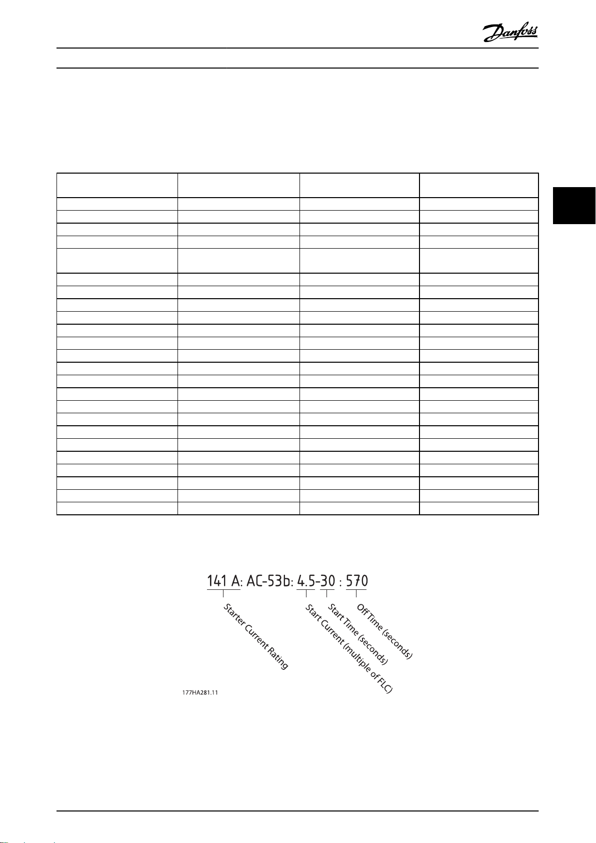
4.3.1 In-line Connection (Bypassed)
NOTE
Models MCD5-0021B - MCD5-0215B are internally bypassed. Models MCD5-0245C - MCD5-1600C require an external bypass
contactor.
AC-53b
3-30:330
MCD5-0021B 21 A 17 A 15 A
MCD5-0037B 37 A 31 A 26 A
MCD5-0043B 43 A 37 A 30 A
MCD5-0053B 53 A 46 A 37 A
AC-53b
3-30:570
MCD5-0068B 68 A 55 A 47 A
MCD5-0084B 84 A 69 A 58 A
MCD5-0089B 89 A 74 A 61 A
MCD5-0105B 105 A 95 A 78 A
MCD5-0131B 131 A 106 A 90 A
MCD5-0141B 141 A 121 A 97 A
MCD5-0195B 195 A 160 A 134 A
MCD5-0215B 215 A 178 A 148 A
MCD5-0245C 255 A 201 A 176 A
MCD5-0360C 360 A 310 A 263 A
MCD5-0380C 380 A 359 A 299 A
MCD5-0428C 430 A 368 A 309 A
MCD5-0595C 620 A 540 A 434 A
MCD5-0619C 650 A 561 A 455 A
MCD5-0790C 790 A 714 A 579 A
MCD5-0927C 930 A 829 A 661 A
MCD5-1200C 1200 A 1200 A 1071 A
MCD5-1410C 1410 A 1319 A 1114 A
MCD5-1600C 1600 A 1600 A 1353 A
AC-53b
4-20:340
AC-53b
4-20:580
AC-53b
4.5-30:330
AC-53b
4.5-30:570
4 4
Table 4.13
AC-53 Rating for Bypassed Operation
4.3.2
Illustration 4.12
All ratings are calculated at altitude of 1000 metres and ambient temperature of 40° C.
MG17K402 - VLT® is a registered Danfoss trademark 17
Page 19
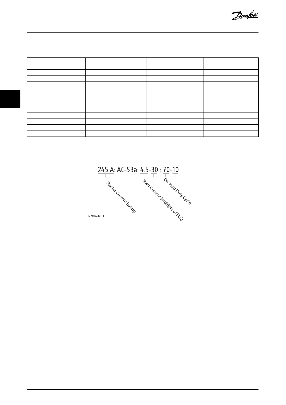
Start Time (seconds)
Starts Per Hour
Electrical Installation MCD 500 Operating Instruction
4.3.3 In-line Connection (Non-bypassed/Continuous)
AC-53a
3-30:50-6
MCD5-0245C 245 A 195 A 171 A
MCD5-0360C 360 A 303 A 259 A
MCD5-0380C 380 A 348 A 292 A
MCD5-0428C 428 A 355 A 300 A
44
Table 4.14
4.3.4
MCD5-0595C 595 A 515 A 419 A
MCD5-0619C 619 A 532 A 437 A
MCD5-0790C 790 A 694 A 567 A
MCD5-0927C 927 A 800 A 644 A
MCD5-1200C 1200 A 1135 A 983 A
MCD5-1410C 1410 A 1187 A 1023 A
MCD5-1600C 1600 A 1433 A 1227 A
AC-53 Rating for Continuous Operation
AC-53a
4-20:50-6
AC-53a
4.5-30:50-6
Illustration 4.13
All ratings are calculated at altitude of 1000 metres and ambient temperature of 40° C.
18 MG17K402 - VLT® is a registered Danfoss trademark
Page 20
Electrical Installation MCD 500 Operating Instruction
4.3.5 Inside Delta Connection (Bypassed)
NOTE
Models MCD5-0021B ~ MCD5-0215B are internally bypassed. Models MCD5-0245C ~ MCD5-1600C require an external bypass
contactor.
AC-53b
3-30:330
MCD5-0021B 32 A 26 A 22 A
MCD5-0037B 56 A 47 A 39 A
MCD5-0043B 65 A 56 A 45 A
MCD5-0053B 80 A 69 A 55 A
AC-53b
3-30:570
MCD5-0068B 102 A 83 A 71 A
MCD5-0084B 126 A 104 A 87 A
MCD5-0089B 134 A 112 A 92 A
MCD5-0105B 158 A 143 A 117 A
MCD5-0131B 197 A 159 A 136 A
MCD5-0141B 212 A 181 A 146 A
MCD5-0195B 293 A 241 A 201 A
MCD5-0215B 323 A 268 A 223 A
MCD5-0245C 383 A 302 A 264 A
MCD5-0360C 540 A 465 A 395 A
MCD5-0380C 570 A 539 A 449 A
MCD5-0428C 645 A 552 A 463 A
MCD5-0595C 930 A 810 A 651 A
MCD5-0619C 975 A 842 A 683 A
MCD5-0790C 1185 A 1072 A 869 A
MCD5-0927C 1395 A 1244 A 992 A
MCD5-1200C 1800 A 1800 A 1607 A
MCD5-1410C 2115 A 1979 A 1671 A
MCD5-1600C 2400 A 2400 A 2030 A
AC-53b
4.20-:340
AC-53b
4-20:580
AC-53b
4.5-30:330
AC-53b
4.5-30:570
4 4
Table 4.15
AC-53 Rating for Bypassed Operation
4.3.6
Illustration 4.14
All ratings are calculated at altitude of 1000 metres and ambient temperature of 40° C.
MG17K402 - VLT® is a registered Danfoss trademark 19
Page 21
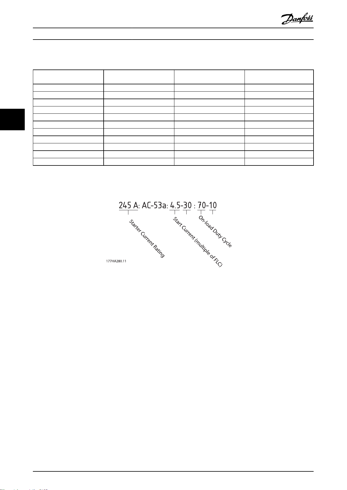
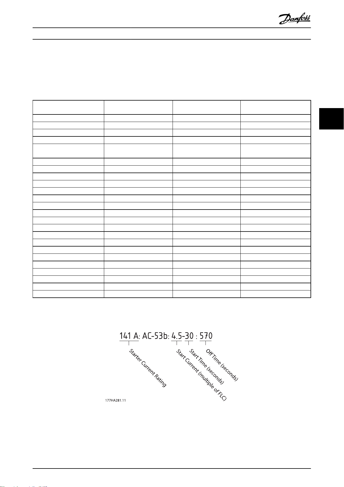
Start Time (seconds)
Starts Per Hour
Electrical Installation MCD 500 Operating Instruction
4.3.7 Inside Delta Connection (Non-bypassed/Continuous)
AC-53a
3-30:50-6
MCD5-0245C 368 A 293 A 257 A
MCD5-0360C 540 A 455 A 389 A
MCD5-0380C 570 A 522 A 438 A
MCD5-0428C 643 A 533 A 451 A
44
Table 4.16
4.3.8
MCD5-0595C 893 A 773 A 629 A
MCD5-0619C 929 A 798 A 656 A
MCD5-0790C 1185 A 1042 A 851 A
MCD5-0927C 1391 A 1200 A 966 A
MCD5-1200C 1800 A 1702 A 1474 A
MCD5-1410C 2115 A 1780 A 1535 A
MCD5-1600C 2400 A 2149 A 1841 A
AC-53 Rating for Continuous Operation
AC-53a
4-20:50-6
AC-53a
4.5-30:50-6
Illustration 4.15
All ratings are calculated at altitude of 1000 metres and ambient temperature of 40° C.
20 MG17K402 - VLT® is a registered Danfoss trademark
Page 22
Electrical Installation MCD 500 Operating Instruction
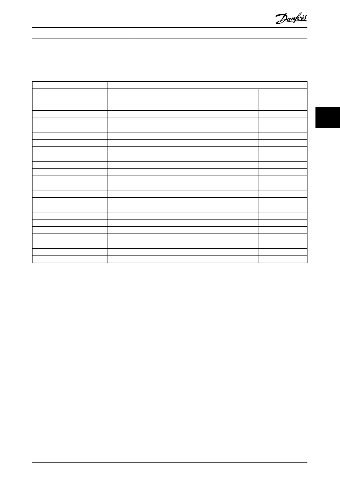
4.4 Minimum and Maximum Current Settings
The MCD 500's minimum and maximum full load current settings depend on the model:
In-line Connection Inside Delta Connection
Model Minimum Maximum Minimum Maximum
MCD5-0021B 5 A 23 A 7 A 34 A
MCD5-0037B 9 A 43 A 13 A 64 A
MCD5-0043B 10 A 50 A 15 A 75 A
MCD5-0053B 11 A 53 A 16 A 79 A
MCD5-0068B 15 A 76 A 23 A 114 A
MCD5-0084B 19 A 97 A 29 A 145 A
MCD5-0089B 20 A 100 A 30 A 150 A
MCD5-0105B 21 A 105 A 32 A 157 A
MCD5-0131B 29 A 145 A 44 A 217 A
MCD5-0141B 34 A 170 A 51 A 255 A
MCD5-0195B 40 A 200 A 60 A 300 A
MCD5-0215B 44 A 220 A 66 A 330 A
MCD5-0245C 51 A 255 A 77 A 382 A
MCD5-0360C 72 A 360 A 108 A 540 A
MCD5-0380C 76 A 380 A 114 A 570 A
MCD5-0428C 86 A 430 A 129 A 645 A
MCD5-0595C 124 A 620 A 186 A 930 A
MCD5-0619C 130 A 650 A 195 A 975 A
MCD5-0790C 158 A 790 A 237 A 1185 A
MCD5-0927C 186 A 930 A 279 A 1395 A
MCD5-1200C 240 A 1200 A 360 A 1800 A
MCD5-1410C 282 A 1410 A 423 A 2115 A
MCD5-1600C 320 A 1600 A 480 A 2400 A
4 4
Table 4.17
4.5
Bypass Contactor
MCD 500 soft starters with model numbers MCD5-0021B - MCD5-0215B are internally bypassed and do not require an
external bypass contactor.
MCD 500 soft starters with model numbers MCD5-0245C - MCD5-1600C are not internally bypassed and may be installed
with an external bypass contactor. Select a contactor with an AC1 rating greater than or equal to the full load current rating
of the connected motor.
4.6 Main Contactor
A main contactor must be installed if the MCD 500 is connected to the motor in inside delta format and is optional for inline connection. Select a contactor with an AC3 rating greater than or equal to the full load current rating of the connected
motor.
4.7 Circuit Breaker
A shunt trip circuit breaker may be used instead of a main contactor to isolate the motor circuit in the event of a soft
starter trip. The shunt trip mechanism must be powered from the supply side of the circuit breaker or from a separate
control supply.
MG17K402 - VLT® is a registered Danfoss trademark 21
Page 23

Electrical Installation MCD 500 Operating Instruction
4.8 Power Factor Correction
If power factor correction is used, a dedicated contactor
should be used to switch in the capacitors. Power factor
correction capacitors must be connected to the input side
of the soft starter.
44
CAUTION
Power factor correction capacitors must be connected to
the input side of the soft starter. Connecting power factor
correction capacitors to the output side will damage the
soft starter.
4.9 Fuses
4.9.1 Power Supply Fuses
Semiconductor fuses can be used for Type 2 coordination
(according to IEC 60947-4-2 standard) and to reduce the
risk of damage to SCRs from transient overload currents.
HRC fuses (such as Ferraz AJT fuses) can be used for Type
1 coordination according to IEC 60947-4-2 standard.
NOTE
Adaptive Acceleration Control (AAC) controls the motor's
speed profile, within the programmed time limit. This may
result in a higher level of current than traditional control
methods.
seconds, motor branch protection should be selected as
follows:
Standard HRC line fuses: Minimum 150% motor
•
full load current
Motor rated line fuses: Minimum rating 100/150%
•
motor full load current
Motor control circuit breaker minimum long time
•
setting: 150% motor full load current
Motor control circuit breaker minimum short time
•
setting: 400% motor full load current for 30
seconds
Fuses recommendations are calculated for 40° C, up to
1000 m.
NOTE
Fuse selection is based on a 400% FLC start for 20 seconds
in conjunction with standard published starts per hour,
duty cycle, 40° C ambient temperature and up to 1000 m
altitude. For installations operating outside these
conditions, consult your local supplier.
NOTE
These fuse tables contain recommendations only, always
consult your local supplier to confirm the selection for
your particular application.
For models marked - there is no suitable fuse.
For applications using Adaptive Acceleration Control to
soft stop the motor with stop times greater than 30
22 MG17K402 - VLT® is a registered Danfoss trademark
Page 24
Electrical Installation MCD 500 Operating Instruction
4.9.2 Bussman Fuses - Square Body (170M)
Model
MCD5-0021B 1150 170M1314 170M1314 170M1314
MCD5-0037B 8000 170M1316 170M1316 170M1316
MCD5-0043B 10500 170M1318 170M1318 170M1318
MCD5-0053B 15000 170M1318 170M1318 170M1318
MCD5-0068B 15000 170M1319 170M1319 170M1318
MCD5-0084B 512000 170M1321 170M1321 170M1319
MCD5-0089B 80000 170M1321 170M1321 170M1321
MCD5-0105B 125000 170M1321 170M1321 170M1321
MCD5-0131B 125000 170M1321 170M1321 170M1321
MCD5-0141B 320000 170M2621 170M2621 170M2621
MCD5-0195B 320000 170M2621 170M2621 170M2621
MCD5-0215B 320000 170M2621 170M2621 170M2621
MCD5-0245C 320000 170M2621 170M2621 170M2621
MCD5-0360C 320000 170M6010 170M6010 170M6010
MCD5-0380C 320000 170M6011 170M6011 MCD5-0428C 320000 170M6011 170M6011 MCD5-0595C 1200000 170M6015 170M6015 170M6014
MCD5-0619C 1200000 170M6015 170M6015 170M6014
MCD5-0790C 2530000 170M6017 170M6017 170M6016
MCD5-0927C 4500000 170M6019 170M6019 170M6019
MCD5-1200C 4500000 170M6021 - MCD5-1410C 6480000 - - MCD5-1600C 12500000 170M6019* - -
SCR I2t (A2s)
Supply Voltage
(≤ 440 VAC)
Supply Voltage
(≤ 575 VAC)
Supply Voltage
(≤ 690 VAC)
4 4
Table 4.18
* Two parallel connected fuses required per phase.
MG17K402 - VLT® is a registered Danfoss trademark 23
Page 25
Electrical Installation MCD 500 Operating Instruction
4.9.3 Bussman Fuses - British Style (BS88)
Model
MCD5-0021B 1150 63FE 63FE 63FE
MCD5-0037B 8000 120FEE 120FEE 120FEE
MCD5-0043B 10500 120FEE 120FEE 120FEE
MCD5-0053B 15000 200FEE 200FEE 200FEE
44
MCD5-0068B 15000 200FEE 200FEE 200FEE
MCD5-0084B 512000 200FEE 200FEE 200FEE
MCD5-0089B 80000 280FM 280FM 280FM
MCD5-0105B 125000 280FM 280FM 280FM
MCD5-0131B 125000 280FM 280FM 280FM
MCD5-0141B 320000 450FMM 450FMM 450FMM
MCD5-0195B 320000 450FMM 450FMM 450FMM
MCD5-0215B 320000 450FMM 450FMM 450FMM
MCD5-0245C 320000 450FMM 450FMM 450FMM
MCD5-0360C 320000 - - MCD5-0380C 320000 400FMM* 400FMM 400FMM*
MCD5-0428C 320000 - - MCD5-0595C 1200000 630FMM* 630FMM* MCD5-0619C 1200000 630FMM* 630FMM* MCD5-0790C 2530000 - - MCD5-0927C 4500000 - - MCD5-1200C 4500000 - - MCD5-1410C 6480000 - - MCD5-1600C 12500000 - - -
SCR I2t (A2s)
Supply Voltage
(< 440 VAC)
Supply Voltage
(< 575 VAC)
Supply Voltage
(< 690 VAC)
Table 4.19
* Two parallel connected fuses required per phase.
24 MG17K402 - VLT® is a registered Danfoss trademark
Page 26
Electrical Installation MCD 500 Operating Instruction
4.9.4 Ferraz Fuses - HSJ
Model
MCD5-0021B 1150 HSJ40** HSJ40**
MCD5-0037B 8000 HSJ80** HSJ80**
MCD5-0043B 10500 HSJ90** HSJ90**
MCD5-0053B 15000 HSJ110** HSJ110**
MCD5-0068B 15000 HSJ125** HSJ125**
MCD5-0084B 51200 HSJ175 HSJ175**
MCD5-0089B 80000 HSJ175 HSJ175
MCD5-0105B 125000 HSJ225 HSJ225
MCD5-0131B 125000 HSJ250 HSJ250**
MCD5-0141B 320000 HSJ300 HSJ300
MCD5-0195B 320000 HSJ350 HSJ350
MCD5-0215B 320000 HSJ400** HSJ400**
MCD5-0245C 320000 HSJ450** HSJ450**
MCD5-0360C 320000
MCD5-0380C 320000
MCD5-0428C 320000
MCD5-0595C 1200000
MCD5-0619C 1200000
MCD5-0790C 2530000
MCD5-0927C 4500000
MCD5-1200C 4500000
MCD5-1410C 6480000
MCD5-1600C 12500000
SCR I2t (A2s)
Supply Voltage
(< 440 VAC)
Not suitable
Supply Voltage
(< 575 VAC)
Not suitable
Supply Voltage
(< 690 VAC)
4 4
Not suitable
Table 4.20
** Two series connected fuses required per phase
MG17K402 - VLT® is a registered Danfoss trademark 25
Page 27
Electrical Installation MCD 500 Operating Instruction
4.9.5 Ferraz Fuses - North American Style (PSC 690)
Model
MCD5-0021B 1150 A070URD30XXX0063 A070URD30XXX0063 MCD5-0037B 8000 A070URD30XXX0125 A070URD30XXX0125 A070URD30XXX0125
MCD5-0043B 10500 A070URD30XXX0125 A070URD30XXX0125 A070URD30XXX0125
MCD5-0053B 15000 A070URD30XXX0125 A070URD30XXX0125 A070URD30XXX0125
44
MCD5-0068B 15000 A070URD30XXX0160 A070URD30XXX0160 A070URD30XXX0160
MCD5-0084B 51200 A070URD30XXX0200 A070URD30XXX0200 A070URD30XXX0200
MCD5-0089B 80000 A070URD30XXX0200 A070URD30XXX0200 A070URD30XXX0200
MCD5-0105B 125000 A070URD30XXX0315 A070URD30XXX0315 A070URD30XXX0315
MCD5-0131B 125000 A070URD30XXX0315 A070URD30XXX0315 A070URD30XXX0315
MCD5-0141B 320000 A070URD30XXX0315 A070URD30XXX0315 A070URD30XXX0315
MCD5-0195B 320000 A070URD30XXX0450 A070URD30XXX0450 A070URD30XXX0450
MCD5-0215B 320000 A070URD30XXX0450 A070URD30XXX0450 A070URD30XXX0450
MCD5-0245C 320000 A070URD30XXX0450 A070URD30XXX0450 A070URD30XXX0450
MCD5-0360C 320000 A070URD33XXX0630 A070URD33XXX0630 A070URD33XXX0630
MCD5-0380C 320000 A070URD33XXX0700 A070URD33XXX0700 MCD5-0428C 320000 A070URD33XXX0700 A070URD33XXX0700 MCD5-0595C 1200000 A070URD33XXX1000 A070URD33XXX1000 A070URD33XXX1000
MCD5-0619C 1200000 A070URD33XXX1000 A070URD33XXX1000 A070URD33XXX1000
MCD5-0790C 2530000 A070URD33XXX1400 A070URD33XXX1400 A070URD33XXX1400
MCD5-0927C 4500000 A070URD33XXX1400 A070URD33XXX1400 A070URD33XXX1400
MCD5-1200C 4500000 A055URD33XXX2250 - MCD5-1410C 6480000 A055URD33XXX2250 - MCD5-1600C 12500000 - - -
SCR I2t (A2s)
Supply Voltage
< 440 VAC
Supply Voltage
< 575 VAC
Supply Voltage
< 690 VAC
Table 4.21
XXX = blade type. Refer to Ferraz catalog for details.
26 MG17K402 - VLT® is a registered Danfoss trademark
Page 28
Electrical Installation MCD 500 Operating Instruction
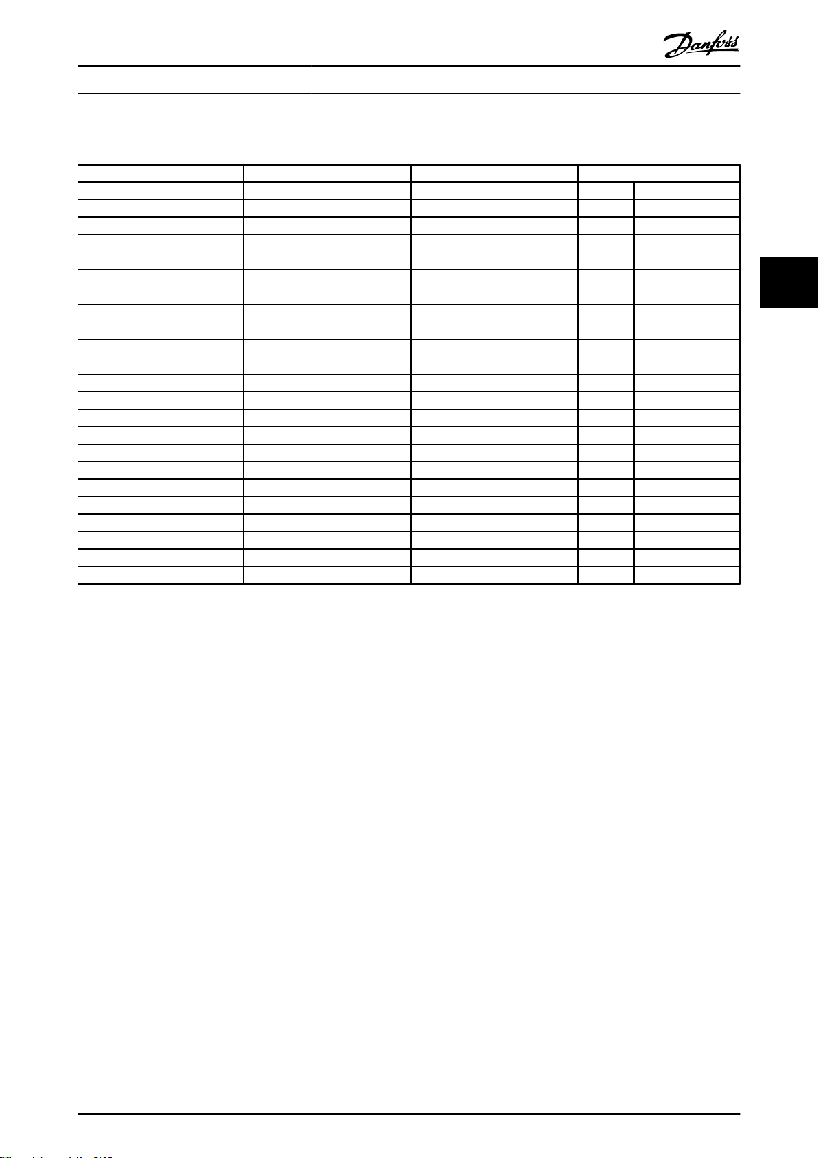
4.9.6 UL Tested Fuses - Short Circuit Ratings
Model Nominal Rating (A) Short Circuit Rating 480V AC (kA) Short Circuit Rating 600V AC (kA) Fuse Ferraz
MCD5-0021B 23 65 10 AJT50 A070URD30XXX0063
MCD5-0037B 43 65 10 AJT50 A070URD30XXX0125
MCD5-0043B 50 65 10 AJT50 A070URD30XXX0125
MCD5-0053B 53 65 10 AJT60 A070URD30XXX0125
MCD5-0068B 76 65 10 AJT80 A070URD30XXX0200
MCD5-0084B 97 65 10 AJT100 A070URD30XXX0200
MCD5-0089B 100 65 10 AJT100 A070URD30XXX0200
MCD5-0105B 105 65 10 AJT125 A070URD30XXX0315
MCD5-0131B 145 65 18 AJT150 A070URD30XXX0315
MCD5-0141B 170 65 18 AJT175 A070URD30XXX0315
MCD5-0195B 200 65 18 AJT200 A070URD30XXX0450
MCD5-0215B 220 65 18 AJT250 A070URD30XXX0450
MCD5-0245C 255 85 85 AJT300 A070URD30XXX0450
MCD5-0360C 360 85 85 AJT400 A070URD33XXX0630
MCD5-0380C 380 85 85 AJT450 A070URD33XXX0700
MCD5-0425B 430 85 85 AJT450 A070URD33XXX0700
MCD5-0595C 620 85 85 A4BQ800 A070URD33XXX1000
MCD5-0619C 650 85 85 A4BQ800 A070URD33XXX1000
MCD5-0790C 790 85 85 A4BQ1200 070URD33XXX1400
MCD5-0927C 930 85 85 A4BQ1200 A070URD33XXX1400
MCD5-1200C 1200 100 100 A4BQ1600 A065URD33XXX1800
MCD5-1410C 1410 100 100 A4BQ2000 A055URD33XXX2250
MCD5-1600C 1600 100 100 A4BQ2500 A055URD33XXX2250
4 4
Table 4.22
MG17K402 - VLT® is a registered Danfoss trademark 27
Page 29
22
21
6/T3
2/T1
13
14
4/T2
24
33
34
06
05
08
07
17
18
25
11
16
A6
A5
A4
5/L3
3/L2
15
E
1/L1
+
24
VDC
+
5
4
2
A
3
1
177HA425.10
Electrical Installation MCD 500 Operating Instruction
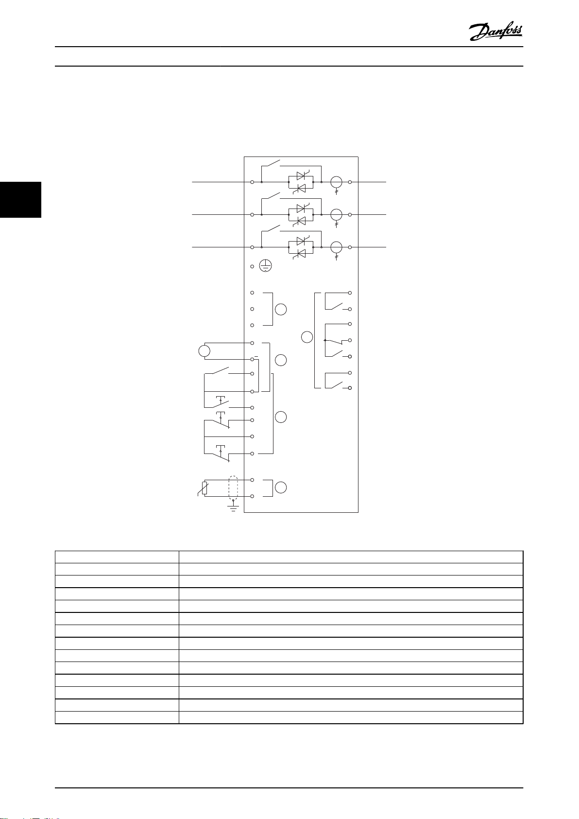
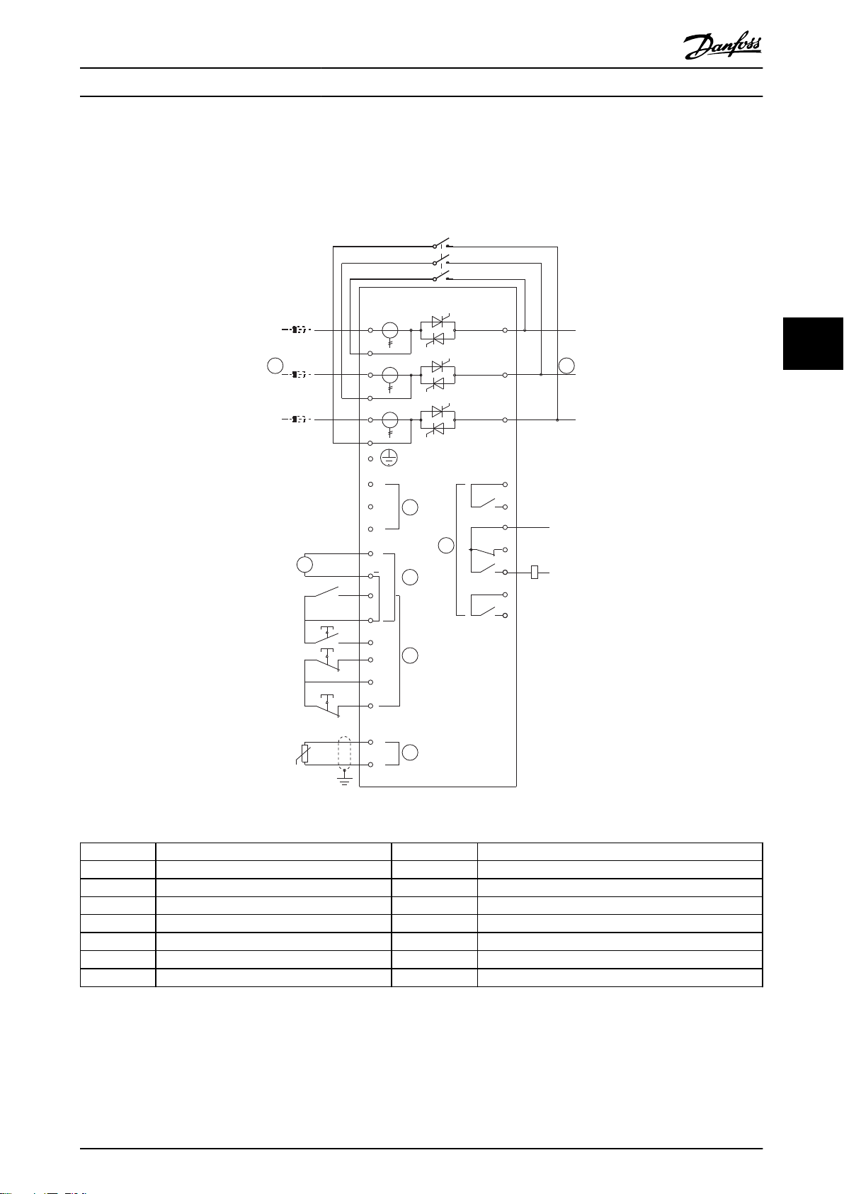
4.10 Schematic Diagrams
4.10.1 Internally Bypassed Models
44
Illustration 4.16
1
2 Outputs
Control supply (model dependent)
07, 08 Programmable analog output
16, 08 24 VDC output
3 Remote control inputs
11, 16 Programmable input
15, 16 Start
17, 18 Stop
25, 18 Reset
4 Motor thermistor input (PTC only)
5 Relay outputs
13, 14 Relay output A
21, 22, 24 Relay output B
33, 34 Relay output C
Table 4.23
28 MG17K402 - VLT® is a registered Danfoss trademark
Page 30
177HA426.11
E
6/T3
2/T1
4/T2
5/L3
3/L2
1/L1
L3B
L2B
L1B
22
21
13
*
*
*
14
24
33
34
06
05
08
07
17
18
25
11
16
A6
A5
A4
15
+
+
5
4
2
A
3
1
24
VDC
Electrical Installation MCD 500 Operating Instruction
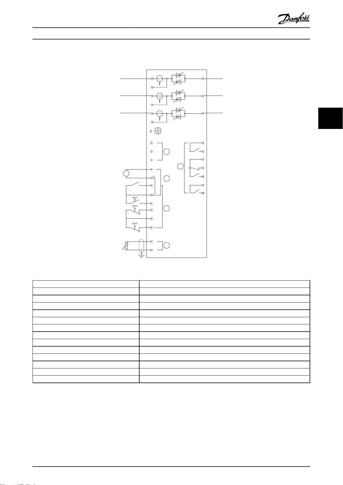
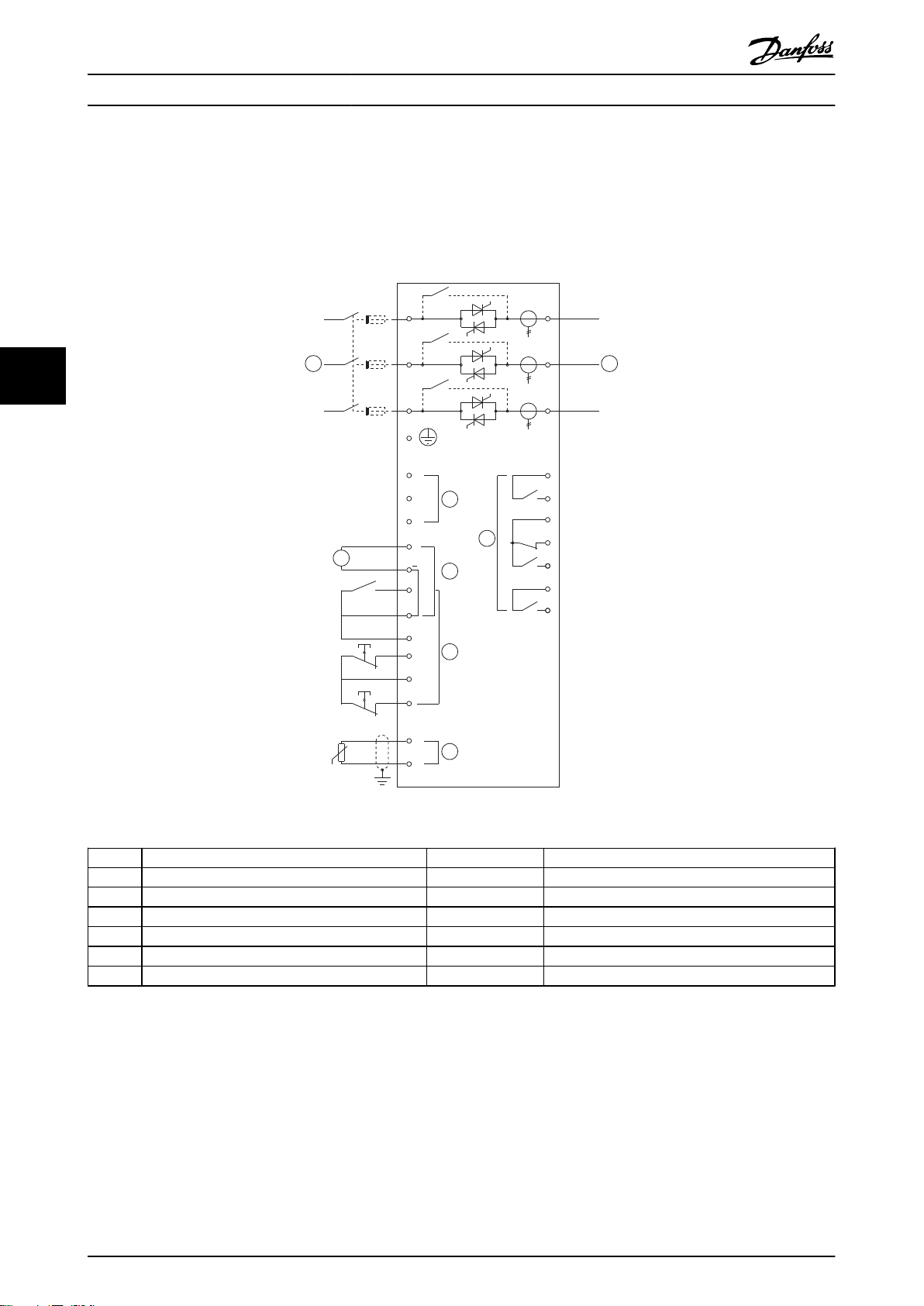
4.10.2 Non-bypassed Models
4 4
Illustration 4.17
1
Control supply (model dependent)
2 Outputs
07, 08 Programmable analog output
16, 08 24 VDC output
3 Remote control inputs
11, 16 Programmable input
15, 16 Start
17, 18 Stop
25, 18 Reset
4 Motor thermistor input (PTC only)
5 Relay outputs
13, 14 Relay output A
21, 22, 24 Relay output B
33, 34 Relay output C
Table 4.24
NOTE
* MCD5-0245C current transformers are located on the output. Bypass terminals are labelled T1B, T2B and T3B.
MG17K402 - VLT® is a registered Danfoss trademark 29
Page 31
100 200 300
1
10
100
1000
10000
177HA596.10
Time in seconds to reach 100% of thermal model
Current (%motor full load current)
3
1
2
400 500
600 700
800 900 1000
Application Examples MCD 500 Operating Instruction
5 Application Examples
The memory function of the model means that
•
5.1 Motor Overload Protection
The thermal model used for motor overload in the MCD
500 has two components:
The overload protection function provided by this model is
Motor windings: These have a low thermal
•
capacity and affects the short term thermal
55
behaviour of the motor. This is where the heat is
generated by the current.
Motor Body: This has a large thermal capacity and
•
affects the long term behaviour of the motor. The
thermal model includes considerations for the
following:
Motor current, iron losses, winding
•
resistance losses, motor body and
winding thermal capacities, cooling
during run and cooling at standstill.
The percentage of the rated capacity of
•
the motor. This sets the displayed value
for the winding model and is affected
by the motor FLC setting amongst
others.
compliant with a NEMA 10 curve, but will provide superior
protection at low levels of overload due to the separation
of the winding thermal model.
the motor is fully protected in “warm start”
situations. The model uses data from the real
time clock to account for elapsed cooling time,
even if control power has been removed.
NOTE
1-1 Motor FLC should be set to the motor's rated FLC. Do
not add the overload rating as this is computed by the
MCD500.
The thermal overload protection used in MCD500 has a
number of advantages over the thermal relays.
The effect of fan cooling is accounted for when
•
the motor is running
The actual full load current and locked rotor time
•
can be used to more accurately tune the model.
The thermal characteristics of the windings are
treated separately from the rest of the motor (ie.
the model recognises that the windings have low
thermal mass and high thermal resistance).
The winding portion of the thermal model
•
responds very rapidly compared with the body
portion, meaning the motor can be run closer to
its safe maximum operating temperature while
still being protected from thermal damage.
The percentage of motor thermal capacity used
•
during each start is stored in memory. The starter
can be configured to automatically determine
whether or not the motor has sufficient thermal
capacity remaining to successfully complete
another start.
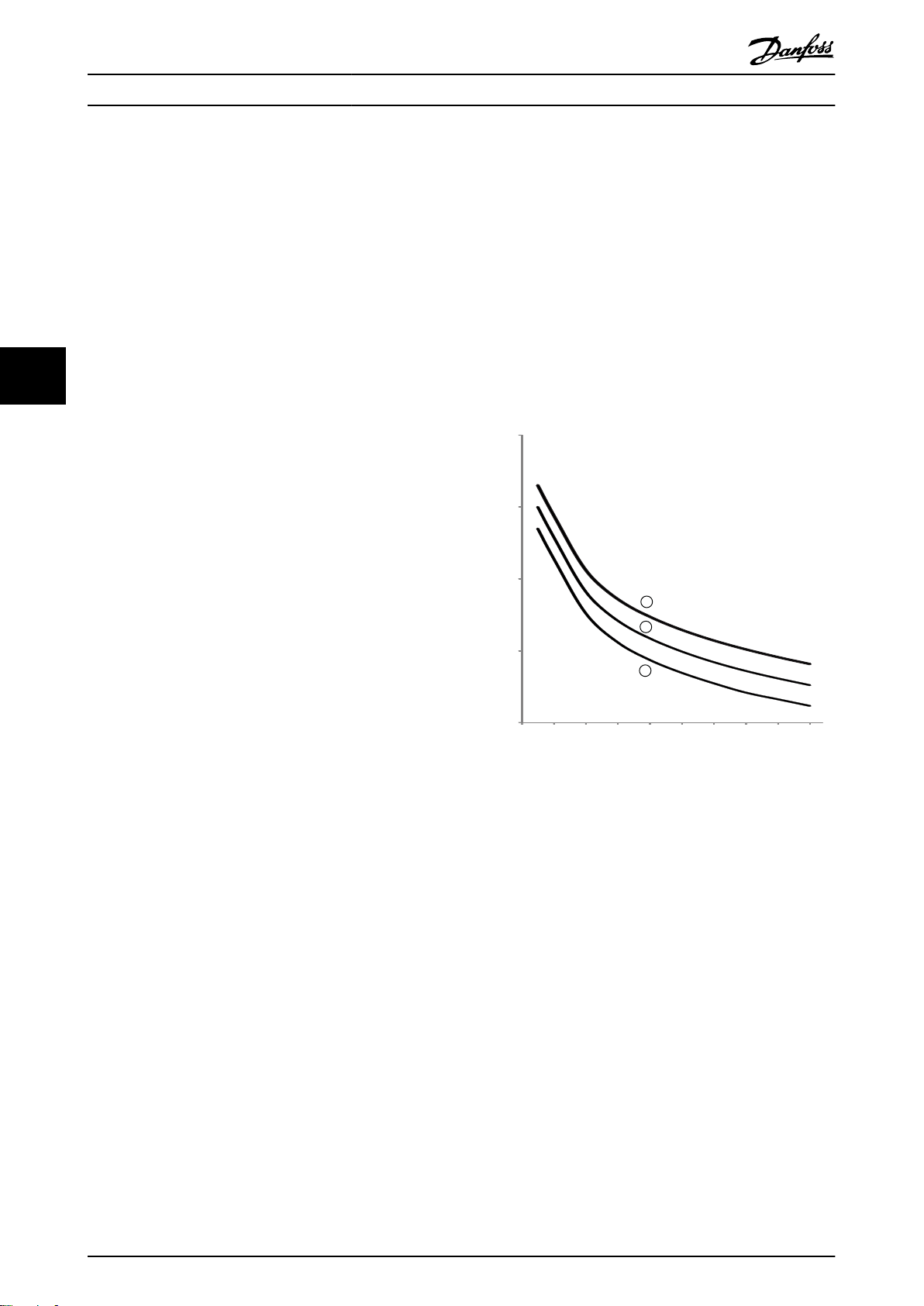
Illustration 5.1
1.
MSTC1 = 5
2.
MSTC1 = 10
3.
MSTC1 = 20
1
MSTC is the Motor Start Time Constant and is defined as
the Locked Rotor Time (in 1-2 Locked Rotor Time) when the
Locked Rotor Current is 600% of FLC.
5.2
AAC Adaptive Acceleration Control
AAC Adaptive Acceleration Control is a new form of motor
control based on the motor's own performance characteristics. With AAC, the user selects the starting or stopping
profile that best matches the load type and the starter
automatically controls the motor to match the profile. The
MCD 500 offers three profiles - early, constant and late
acceleration and deceleration.
30 MG17K402 - VLT® is a registered Danfoss trademark
Page 32
700%
600%
500%
300%
100%
400%
200%
10% 20% 30% 40% 50%
Rotor speed (% full speed)
60% 70% 80% 90% 100%
177HA289.11
Current (% motor full load current)
1
3
2
700%
600%
500%
300%
100%
400%
200%
10% 20% 30% 40% 50% 60% 70% 80% 90% 100%
177HA290.10
CURRENT (% Motor Full Load Current)
ROTOR SPEED (% Full Speed)
Full Voltage Stator Current
Current Limit (e.g. Par. 2 = 400% x FLC)
Initial Current (e.g. Par. 3 = 250% x FLC)
Ramp Time
(eg Par. 4 = 10 secs)
Application Examples MCD 500 Operating Instruction
AAC uses two algorithms, one to measure the motor's
characteristics and one to control the motor. The MCD 500
uses the first start to determine the motor's characteristics
at zero speed and at maximum speed. During each
subsequent start and stop, the starter dynamically adjusts
its control to ensure the motor's actual performance
matches the selected profile throughout the start. The
starter increases power to the motor if the actual speed is
too low for the profile, or decreases power if the speed is
too high.
5.3 Starting Modes
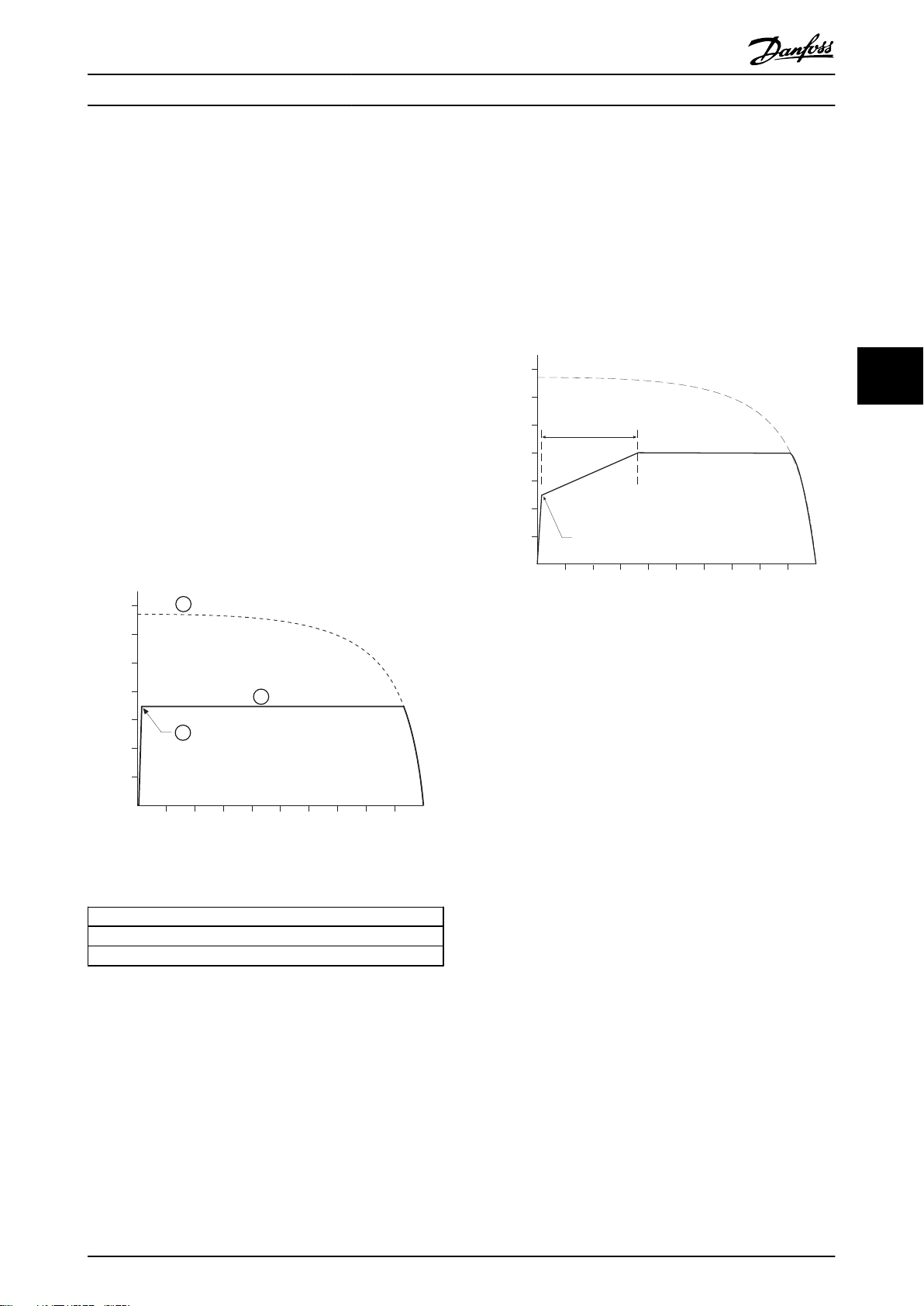
5.3.1 Constant Current
Constant current is the traditional form of soft starting,
which raises the current from zero to a specified level and
keeps the current stable at that level until the motor has
accelerated.
Constant current starting is ideal for applications where
the start current must be kept below a particular level.
1-5 Initial Current to a level that will start the
Set
motor with a light load, and 1-4 Current Limit to a
level that will start the motor with a heavy load.
the load breaks away easily, but starting time
•
needs to be extended (for example a centrifugal
pump where pipeline pressure needs to build up
slowly).
the electricity supply is limited (for example a
•
generator set), and a slower application of load
will allow greater time for the supply to respond.
5 5
Illustration 5.2
1: 1-5 Initial current
2: 1-4 Current limit
3: Full voltage current
Table 5.1
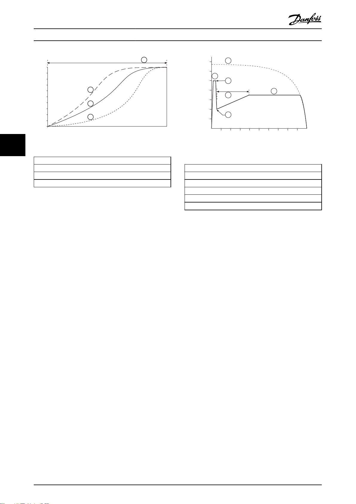
5.3.2
Current Ramp
Illustration 5.3
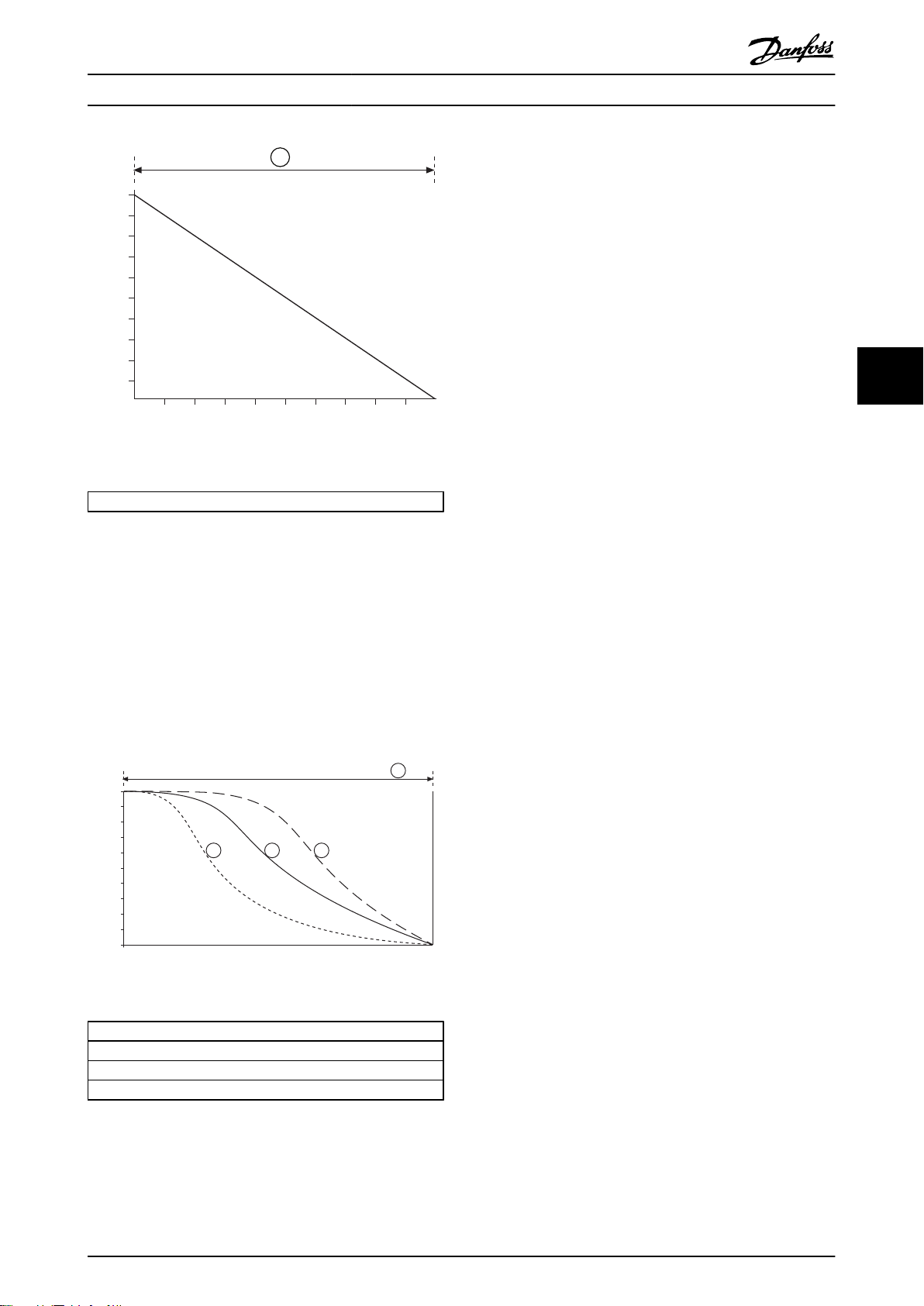
AAC Adaptive Acceleration Control
5.3.3
To use AAC Adaptive Acceleration Control to control
starting performance:
1.
Select Adaptive Control in 1-3 Start Mode.
2.
Set 1-6 Start Ramp Time.
3.
Select the desired profile in 1-13 Adaptive Start
Profile.
4.
Set 1-4 Current Limit sufficiently high to allow a
successful start. The first AAC start will be a
Constant Current start. This allows the MCD 500
to learn the characteristics of the connected
motor. This motor data is used by the MCD 500
during subsequent AAC Adaptive Acceleration
Control starts.
Current ramp soft starting raises the current from a
specified starting level (1) to a maximum limit (3), over an
extended period of time (2).
Current ramp starting can be useful for applications where:
•
the load can vary between starts (for example a
conveyor which may start loaded or unloaded).
MG17K402 - VLT® is a registered Danfoss trademark 31
Page 33
0
10%
20%
30%
40%
50%
Time
60%
70%
80%
90%
100%
4
177HA507.10
Speed
1
2
3
700%
600%
500%
300%
100%
400%
200%
10% 20% 30% 40% 50%
Rotor speed (% full speed)
60% 70% 80% 90% 100%
177HA508.10
Current (% motor full load current)
1
5
4
6
3
2
Application Examples MCD 500 Operating Instruction
Illustration 5.4
55
1. Early acceleration
2. Constant acceleration
3. Late acceleration
4. 1-16 Start Ramp Time
Table 5.2 1-13 Adaptive Start Profile
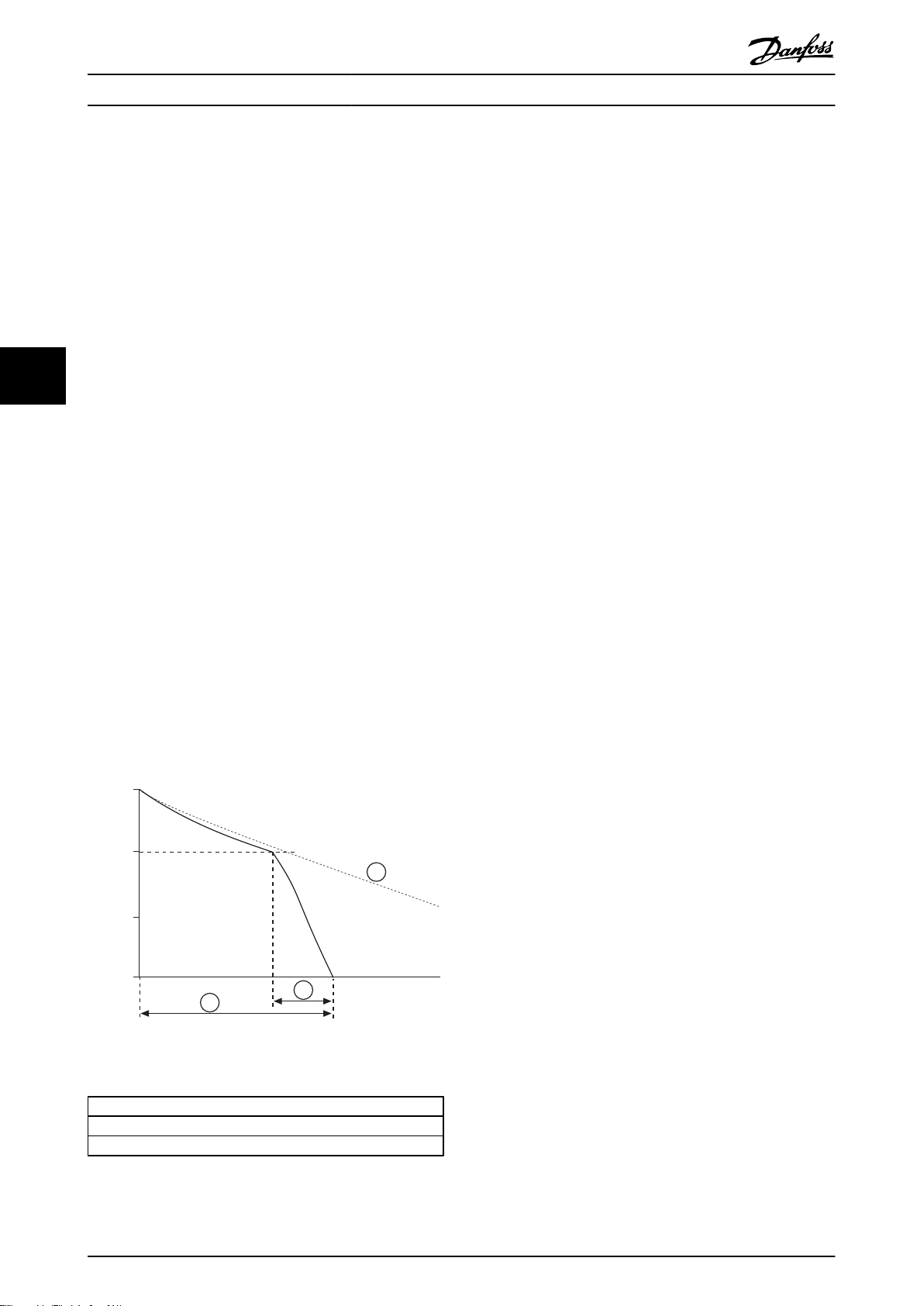
Illustration 5.5
1: 1-7 Kickstart Level
2: 1-8 Kickstart Time
3: 1-5 Initial Current
4: 1-6 Start Ramp Time
5: 1-4 Current Limit
6: Full voltage current
NOTE
AAC Adaptive Acceleration Control will control the load
according to the programmed profile. Start current will
vary according to the selected acceleration profile and the
programmed start time.
If replacing a motor connected to an MCD 500
programmed for AAC Adaptive Control starting or
stopping, or if the starter has been tested on a different
motor prior to actual installation, the starter will need to
learn the characteristics of the new motor. The MCD 500
will automatically re-learn the motor's characteristics if 1-1
Motor Full Load Current or 1-12 Adaptive Control Gain is
changed.
Table 5.3
5.4
Stopping Modes
5.4.1 Coast to Stop
Coast to stop lets the motor slow at its natural rate, with
no control from the soft starter. The time required to stop
will depend on the type of load.
TVR Soft Stop
5.4.2
Kickstart
5.3.4
Kickstart provides a short boost of extra torque at the
Timed voltage ramp reduces the voltage to the motor
gradually over a defined time. The load may continue to
run after the stop ramp is complete.
beginning of a start, and can be used in conjunction with
current ramp or constant current starting.
Timed voltage ramp stopping can be useful for
applications where the stop time needs to be extended, or
Kickstart can be useful to help start loads that require high
to avoid transients on generator set supplies.
breakaway torque but then accelerate easily (for example
flywheel loads such as presses).
32 MG17K402 - VLT® is a registered Danfoss trademark
Page 34
70%
60%
50%
30%
10%
40%
Time
Voltage (% full voltage)
20%
80%
90%
100%
177HA509.10
1
0
10%
20%
30%
40%
50%
Time
Speed
60%
70%
80%
90%
100%
177HA510.10
1 2
4
3
Application Examples MCD 500 Operating Instruction
NOTE
Adaptive control does not actively slow the motor down
and will not stop the motor faster than a coast to stop. To
shorten the stopping time of high inertia loads, use brake.
The first AAC Adaptive Deceleration Control stop will be a
normal soft stop. This allows the MCD 500 to learn the
characteristics of the connected motor. This motor data is
used by the MCD 500 during subsequent Adaptive Control
stops.
Illustration 5.6
1: 1-11 Stop Time
Table 5.4
AAC Adaptive Acceleration Control
5.4.3
To use AAC Adaptive Acceleration Control to control
stopping performance:
1.
Select Adaptive Control in 1-10 Stop Mode.
2.
Set 1-11 Stop Time.
3.
Select the required profile in 1-14 Adaptive Stop
Profile.
NOTE
Adaptive Control will control the load according to the
programmed profile. Stopping current will vary according
to the selected deceleration profile and stop time.
If replacing a motor connected to an MCD 500
programmed for AAC Adaptive Control starting or
stopping, or if the starter has been tested on a different
motor prior to actual installation, the starter will need to
learn the characteristics of the new motor. The MCD 500
will automatically re-learn the motor's characteristics if 1-1
Motor Full Load Current or 1-12 Adaptive Control Gain is
changed.
Brake
5.4.4
Brake reduces the time the motor requires to stop.
During braking an increased noise level from the motor
may be audible. This is a normal part of motor braking.
CAUTION
If the brake torque is set too high, the motor will stop
before the end of the brake time and the motor will suffer
unnecessary heating which could result in damage. Careful
configuration is required to ensure safe operation of the
starter and motor.
5 5
Illustration 5.7
1. Early deceleration
2. Constant deceleration
3. Late deceleration
4. 1-10 Stop Time
Table 5.5 1-14 AAC Adaptive Stop Profile
CAUTION
A high brake torque setting can result in peak currents up
to motor DOL being drawn while the motor is stopping.
Ensure protection fuses installed in the motor branch
circuit are selected appropriately.
NOTE
Brake operation causes the motor to heat faster than the
rate calculated by the motor thermal model. If you are
using brake, install a motor thermistor or allow sufficient
restart delay (2-11 Restart Delay).
When brake is selected, the MCD 500 uses DC injection to
slow the motor.
MG17K402 - VLT® is a registered Danfoss trademark 33
Page 35
100%
70%
0%
30%
1
2
3
177HA511.10
Time
Speed
Application Examples MCD 500 Operating Instruction
MCD 500 braking
Does not require the use of a DC brake contactor
•
Controls all three phases so that the braking
•
currents and associated heating are evenly
distributed through the motor
Braking has two stages
1. Pre-brake: provides an intermediate level of
braking to slow motor speed to a point where
full brake can be operated successfully (approxi-
55
To configure the MCD 500 for brake operation
mately 70% speed).
2. Full brake: brake provides maximum braking
torque but is ineffective at speeds greater than
approximately 70%.
1.
Set 1-11 Stop Time for the desired stopping time
duration (1). This is the total braking time and
must be set sufficiently longer than the brake
time (1-16 Brake Time) to allow the pre-braking
stage to reduce motor speed to approximately
70%. If the stop time is too short, braking will not
be successful and the motor will coast to stop.
2.
Set 1-16 Brake Time to approximately one quarter
of the programmed Stop Time. This sets the time
for the Full Brake stage (2).
3.
Adjust 1-15 Brake Torque so that the desired
stopping performance is achieved. If set too low,
the motor will not stop completely and will coast
to stop by the end of the braking period.
NOTE
When using DC brake, the mains supply must be
connected to the soft starter (input terminals L1, L2, L3) in
positive phase sequence and 2-1 Phase Sequence must be
set to Positive only.
NOTE
For loads which may vary between braking cycles, install a
zero speed sensor to ensure that the soft starter ends DC
braking when the motor stops. This avoids unnecessary
heating of the motor.
For more information on using the MCD 500 with an
external speed sensor, see 5.12 DC Brake with External Zero
Speed Sensor.
5.5 Jog Operation
Jog runs the motor at reduced speed, to allow alignment
of the load or to assist servicing. The motor can be jogged
in either forward or reverse direction.
The maximum available torque for jog is approximately
50% - 75% of motor full load torque (FLT) depending on
the motor. Available jog torque in reverse is approximately
50% - 75% of the jog torque in forward direction. To set
the jog torque level, use 15-8 Jog Torque.
NOTE
Setting 15-8 Jog Torque above 50% may cause increased
shaft vibration.
Illustration 5.8
1: 1-11 Stop Time
2: 1-16 Brake Time
3: Coast to stop time
Table 5.6
34 MG17K402 - VLT® is a registered Danfoss trademark
Page 36
70%
60%
50%
30%
10%
40%
20%
80%
90%
100%
177HA512.10
3
1
2
Application Examples MCD 500 Operating Instruction
CAUTION
Slow speed running is not intended for continuous
operation due to reduced motor cooling. Jog changes the
motor's heating profile and reduced the accuracy of the
motor thermal model. Do not rely on motor overload
protection to protection to protect the motor during jog
operation.
5.6 Inside Delta Operation
AAC, Jog and Brake functions are not supported in inside
delta (six-wire) operation. If these functions are
programmed when the starter is connected inside delta
the behaviour is as given below:
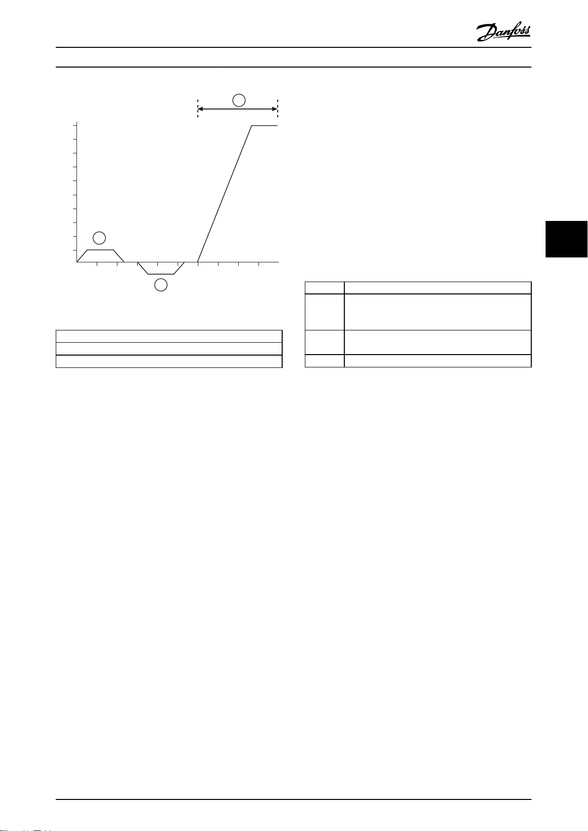
AAC Start The starter performs a Constant Current Start.
Illustration 5.9
1. Jog Forward
2. Jog Reverse
3. Normal Operation
AAC Stop The starter performs a TVR Soft Stop if Stop Time is
Jog The starter issues a warning with the error message
Brake The starter performs a Coast to Stop.
5 5
>0 secs. If Stop Time is set to 9 secs the starter
performs a Coast to Stop.
Unsupported Option.
Table 5.7
To activate jog operation, use a programmable input (3-3
Input A Function).
To stop a jog operation, perform either of the following:
Remove the jog command
•
Press the OFF button on the LCP
•
Activate Emergency Stop using the LCP
•
programmable inputs
Jog will recommence at the end of a restart delay if the
jog command is still present. All other commands except
the above will be ignored during jog operation.
NOTE
Jog will operate in 2-wire mode regardless of the state of
the remote Start, Stop and Reset inputs.
NOTE
Jog is only available for the primary motor (for more
information on primary and secondary sets, see Secondary
motor set. Soft start and soft stop are not available during
jog operation.
MG17K402 - VLT® is a registered Danfoss trademark 35
Table 5.8
NOTE
When connected in inside delta, current imbalance is the
only phase loss protection that is active during run. Do not
disable current imbalance protection during inside delta
operation.
NOTE
Inside delta operation is only possible with mains voltage
≤ 600 VAC.
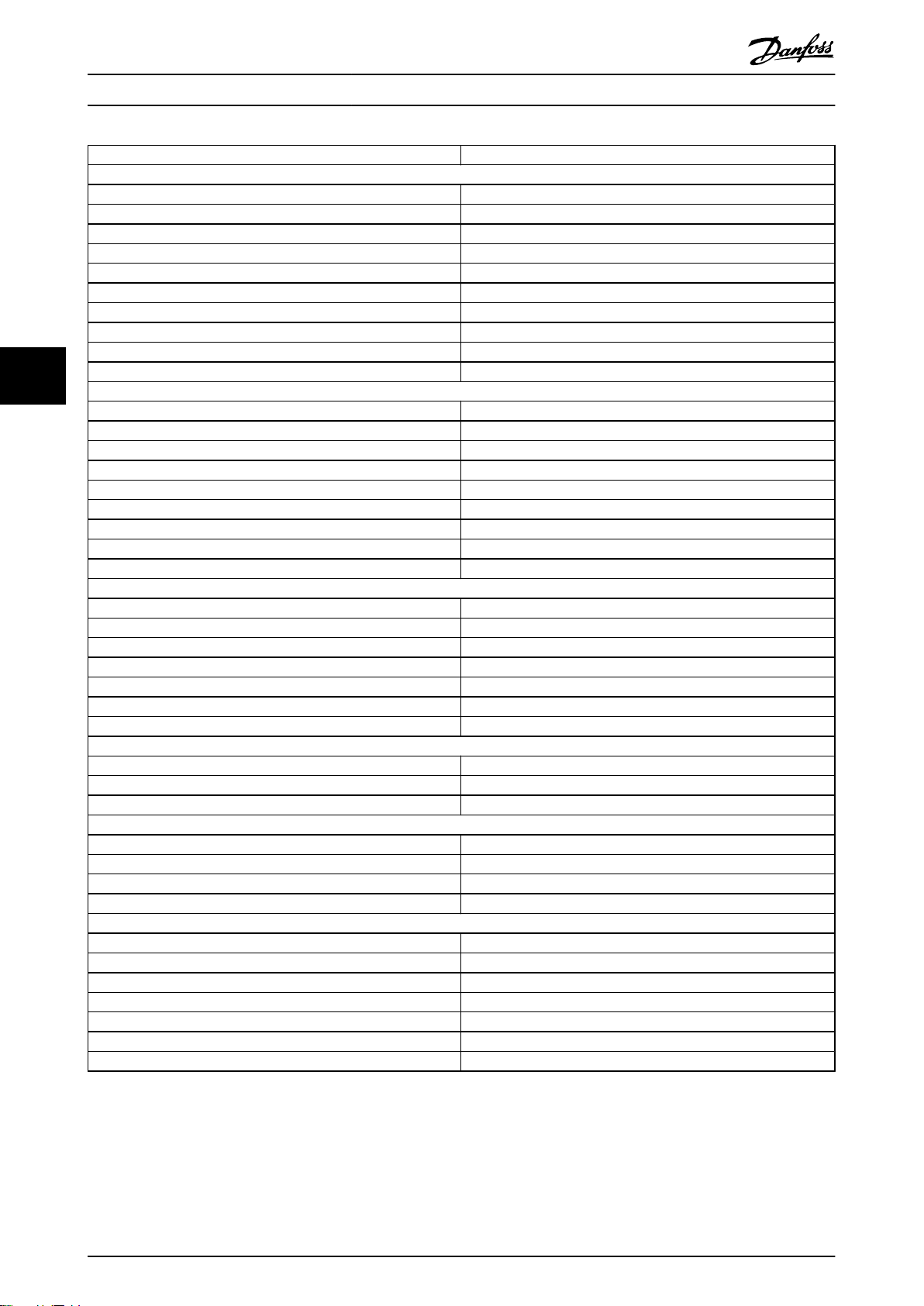
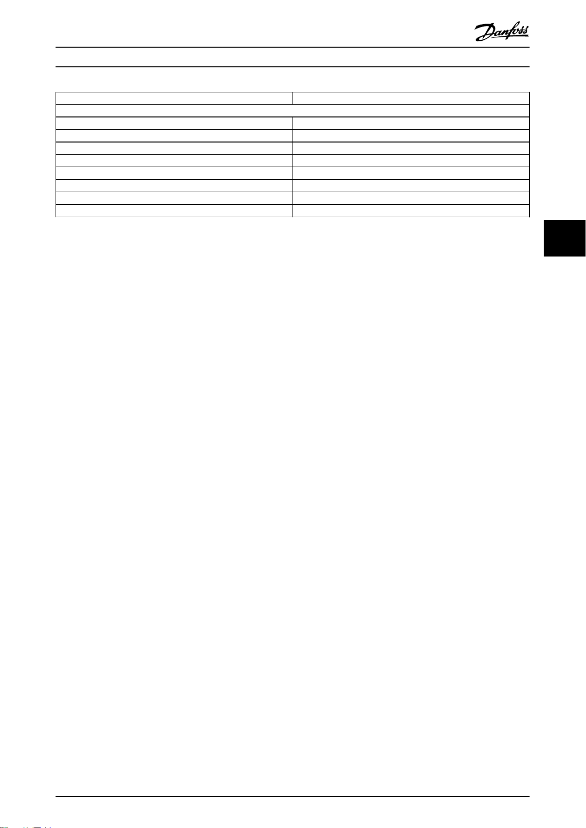
5.7 Typical Start Currents
Use this information to determine the appropriate start
current for your application.
NOTE
These start current requirements are appropriate and
typical in most circumstances, However, the performance
and start torque requirements of motors and machines do
vary. For further assistance, contact your local supplier.
Page 37
Application Examples MCD 500 Operating Instruction
Application Typical Start Current
General & Water
Agitator 4.0 x FLC
Centrifugal pump 3.5 x FLC
Compressor (Screw, unloaded) 3.0 x FLC
Compressor (Reciprocating, unloaded) 4.0 x FLC
Conveyor 4.0 x FLC
Fan (damped) 3.5 x FLC
Fan (undamped) 4.5 x FLC
Mixer 4.5 x FLC
Positive displacement pump 4.0 x FLC
55
Submersible pump 3.0 x FLC
Metals & Mining
Belt conveyor 4.5 x FLC
Dust collector 3.5 x FLC
Grinder 3.0 x FLC
Hammer mill 4.5 x FLC
Rock crusher 4.0 x FLC
Roller conveyor 3.5 x FLC
Roller mill 4.5 x FLC
Tumbler 4.0 x FLC
Wire draw machine 5.0 x FLC
Food Processing
Bottle washer 3.0 x FLC
Centrifuge 4.0 x FLC
Dryer 4.5 x FLC
Mill 4.5 x FLC
Palletiser 4.5 x FLC
Separator 4.5 x FLC
Slicer 3.0 x FLC
Pulp and Paper
Dryer 4.5 x FLC
Re-pulper 4.5 x FLC
Shredder 4.5 x FLC
Petrochemical
Ball mill 4.5 x FLC
Centrifuge 4.0 x FLC
Extruder 5.0 x FLC
Screw conveyor 4.0 x FLC
Transport & Machine Tool
Ball mill 4.5 x FLC
Grinder 3.5 x FLC
Material conveyor 4.0 x FLC
Palletiser 4.5 x FLC
Press 3.5 x FLC
Roller mill 4.5 x FLC
Rotary table 4.0 x FLC
Table 5.9
36 MG17K402 - VLT® is a registered Danfoss trademark
Page 38
Application Examples MCD 500 Operating Instruction
Application Typical Start Current
Lumber & Wood products
Bandsaw 4.5 x FLC
Chipper 4.5 x FLC
Circular saw 3.5 x FLC
Debarker 3.5 x FLC
Edger 3.5 x FLC
Hydraulic power pack 3.5 x FLC
Planer 3.5 x FLC
Sander 4.0 x FLC
Table 5.10
5 5
MG17K402 - VLT® is a registered Danfoss trademark 37
Page 39
KM1
KM1
F1
22
21
6/T3
2/T1
13
14
4/T2
24
33
34
06
05
08
07
17
18
25
11
16
A6
A5
A4
5/L3
3/L2
15
S1
S2
E
1/L1
+
+
5
6 7
4
2
A
3
1
177HA522.10
24
VDC
Application Examples MCD 500 Operating Instruction
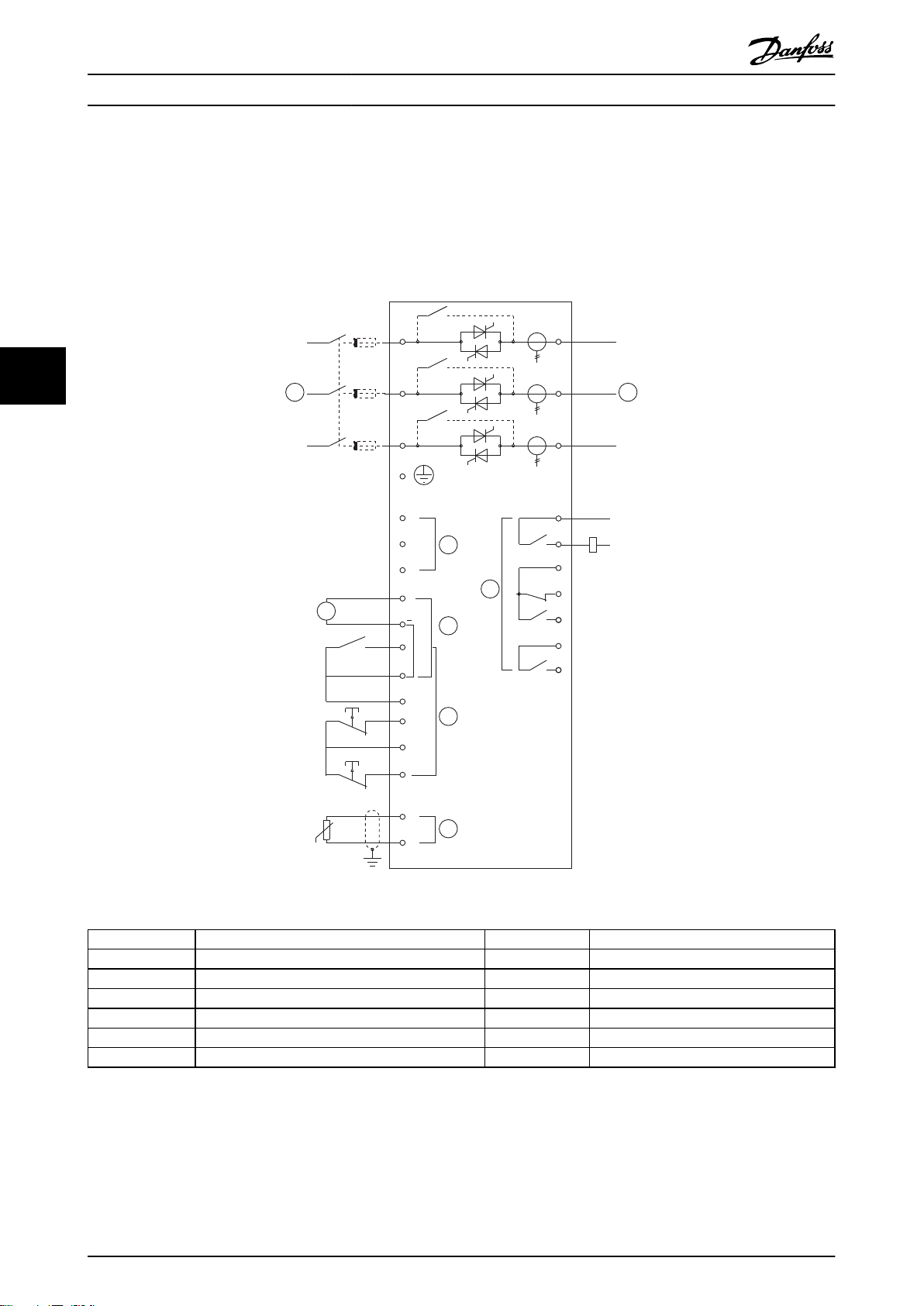
5.8 Installation with Main Contactor
The MCD 500 is installed with a main contactor (AC3 rated). Control voltage must be supplied from the input side of the
contactor.
The main contactor is controlled by the MCD 500 Main Contactor output, which by default is assigned to Output Relay A
(terminals 13, 14).
55
Illustration 5.10
1
2 24 VDC output F1 Semiconductor fuses (optional)
3 Remote control inputs S1 Start /stop
4 Motor thermistor input (PTC only) S2 Reset contact
5 Relay outputs 13, 14 Relay output A
6 3-phase supply 21, 22, 24 Relay output B
7 Motor terminals 33, 34 Relay output C
Table 5.11
Parameter settings:
4-1 Relay A Function
•
Control voltage (model dependent) KM1 Main contactor
Select Main Contactor - assigns the Main Contactor function to Relay Output A (default value).
•
38 MG17K402 - VLT® is a registered Danfoss trademark
Page 40
KM1
24
VDC
22
21
13
14
24
33
34
06
05
08
07
17
18
25
11
16
A6
A5
A4
15
S1
S2
S3
E
+
+
6/T3
2/T1
4/T2
5/L3
3/L2
1/L1
L3B
L1B
L2B
KM1
F1
5
6 7
4
2
A
3
1
177HA523.10
Application Examples MCD 500 Operating Instruction
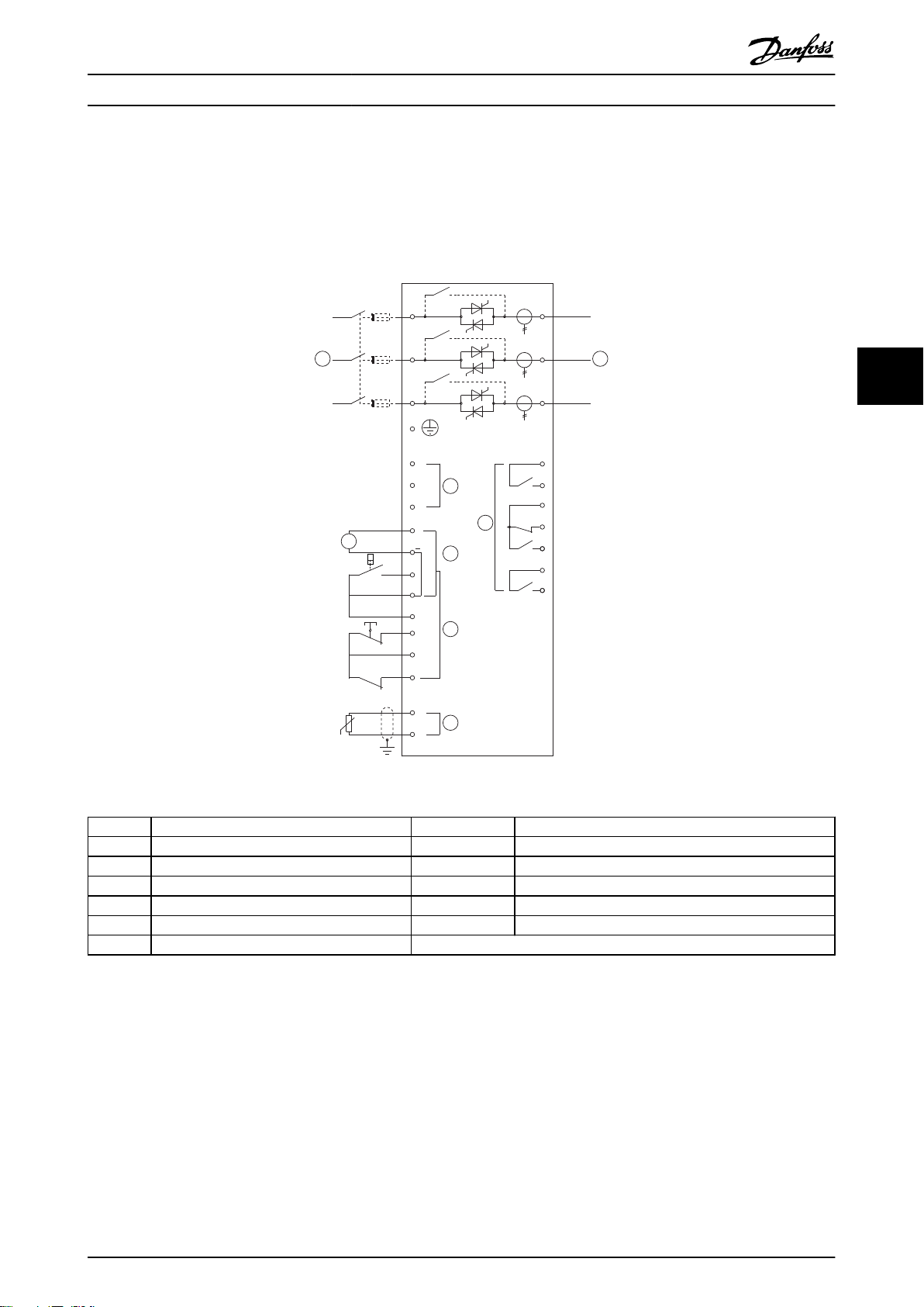
5.9 Installation with Bypass Contactor
The MCD 500 is installed with a bypass contactor (AC1 rated). The bypass contactor is controlled by the MCD 500 Run
Output which by default is assigned to Output Relay B (terminals 21, 22, 24).
5 5
Illustration 5.11
1
2 24 VDC output F1 Semiconductor fuses (optional)
3 Remote control inputs S1 Start contact
4 Motor thermistor input (PTC only) S2 Stop contact
5 Relay outputs S3 Reset contact
6 3-phase supply 13, 14 Relay output A
7 Motor terminals 21, 22, 24 Relay output B
33, 34 Relay output C
Table 5.12
Parameter settings:
•
Control voltage (model dependent) KM1 Bypass contactor
4-4 Relay B Function
Select Run - assigns the run output function to Relay Output B (default value).
•
MG17K402 - VLT® is a registered Danfoss trademark 39
Page 41
KM1
F1
24
VDC
22
21
6/T3
2/T1
13
14
4/T2
24
33
34
06
05
08
07
17
18
25
11
16
A6
A5
A4
5/L3
3/L2
15
S3
S1
S2
E
1/L1
+
+
5
6 7
4
2
A
3
1
177HA524.10
Application Examples MCD 500 Operating Instruction
5.10 Emergency Run Operation
In normal operation the MCD 500 is controlled via a remote two wire signal (terminals 17, 18).
Emergency Run is controlled by a two wire circuit connected to Input A (terminals 11, 16). Closing Input A causes the MCD
500 to run the motor and ignore all trip conditions.
55
Illustration 5.12
1
2 24 VDC output S2 Reset contact
Control voltage (model dependent) S1 Start/stop contact
3 Remote control inputs S3 Emergency Run contact
4 Motor thermistor input (PTC only) 13, 14 Relay output A
5 Relay outputs 21, 22, 24 Relay output B
6 3-phase supply 33, 34 Relay output C
7 Motor terminals
Table 5.13
Parameter settings:
•
•
3-3 Input A Function
•
15-3 Emergency Run
•
Select Emergency Run - assigns Input A to Emergency Run Function
Select Enable - Enables the Emergency Run mode
40 MG17K402 - VLT® is a registered Danfoss trademark
Page 42
KM1
F1
24
VDC
22
21
6/T3
2/T1
13
14
4/T2
24
33
34
06
05
08
07
17
18
25
11
16
A6
A5
A4
5/L3
3/L2
15
S3
S1
S2
E
1/L1
+
+
5
6 7
4
2
A
3
1
177HA525.10
Application Examples MCD 500 Operating Instruction
5.11 Auxiliary Trip Circuit
In normal operation the MCD 500 is controlled via a remote two wire signal (terminals 17, 18).
Input A (terminals 11, 16) is connected to an external trip circuit (such as a low pressure alarm switch for a pumping
system). When the external circuit activates, the soft starter trips, which stops the motor.
5 5
Illustration 5.13
Control voltage (model dependent) S1 Start/stop contact
1
2 24 VDC output S2 Reset contact
3 Remote control inputs S3 Auxiliary trip contact
4 Motor thermistor input (PTC only) 13, 14 Relay output A
5 Relay outputs 21, 22, 24 Relay output B
6 3-phase supply 33, 34 Relay output C
7 Motor terminals
Table 5.14
Parameter settings:
3-3 Input A Function
•
•
•
•
3-4 Input A Name
•
3-8 Remote Reset Logic
•
Select Input Trip (N/O) assigns the Input A to Auxiliary Trip (N/O) function
Select a name e.g. Low Pressure - assigns a name to Input A.
Select as required e.g. Normally Closed - the input behaves like a normally closed contact.
MG17K402 - VLT® is a registered Danfoss trademark 41
Page 43
-F1
L3L2L1 N E
-KA1
L1 L2 L3
E
T1 T2 T3
A5A4 A6
15 16 17 18 25
11 16
-KA1
-KA2
-KA1
-KA2
T3T2T1
M
3
-KA2-KA1
-A2
177HA619.10
4
1
3
2
5
A B C D E
6
7
5
8
Application Examples MCD 500 Operating Instruction
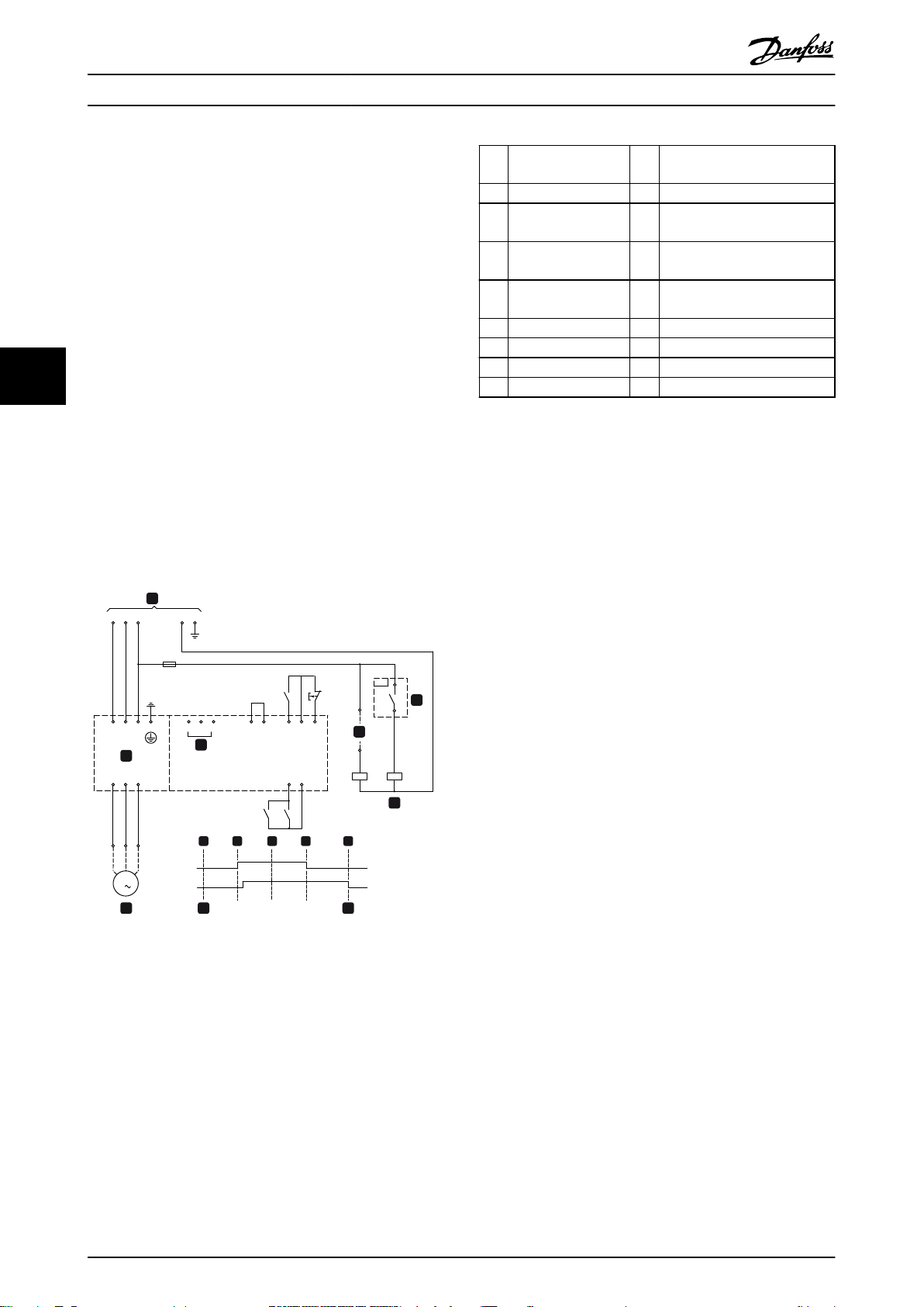
5.12 DC Brake with External Zero Speed
Sensor
1 Soft starter 4 Emergency stop mode (shown
on starter display)
2 Control voltage A Off (ready)
For loads which may vary between braking cycles, there
15,16Start B Start
are benefits in using an external zero-speed sensor to
interface with the MCD 500 for brake shut-off. This control
17,18Stop C Run
method ensures that the MCD 500 braking will always shut
off when the motor has reached a standstill, thus avoiding
25,18Reset D Stop
unnecessary motor heating.
2 Motor E Zero speed
The following schematic diagram shows how you can use
a zero-speed sensor with the MCD 500 to turn the brake
55
function off at motor standstill. The zero-speed sensor (-
3 Three-phase supply 5 Start signal (2, 3, or 4-wire)
6 Zero speed detect
7 Zero speed sensor
A2) is often referred to as an under-speed detector. Its
internal contact is open at zero-speed and closed at any
Table 5.15
speed above zero-speed. Once the motor has reached a
standstill, the MCD 500 will go into Emergency Stop mode
For details on configuring DC Brake, see 5.4.4 Brake.
and remain in this state until the next start command is
given (i.e. next application of –KA1).
NOTE
When using DC brake, the mains supply must be
The MCD 500 must be operated in remote mode and 3-3
Input A Function must be set to emergency stop.
connected to the soft starter (input terminals L1, L2, L3) in
positive phase sequence and 2-1 Phase Sequence must be
set to Positive only.
5.13 Soft Braking
For high inertia loads the MCD 500 can be configured for
soft braking.
In this application the MCD 500 is employed with forward
run and braking contactors. When MCD 500 receives a
start signal (button S1), it closes the forward run contactor
(KM1) and controls the motor according to the
programmed primary motor settings.
When the MCD 500 receives a stop signal (button S2), it
opens the forward run contactor (KM1) and closes the
braking contactor (KM2) after a delay of approximately 2-3
seconds (KT1). KA3 is also closed to activate the secondary
motor settings, which should be user programmed for the
Illustration 5.14
42 MG17K402 - VLT® is a registered Danfoss trademark
desired stopping performance characteristics.
When motor speed approaches zero, the external shaft
rotation sensor (A2) stops the soft starter and opens the
braking contactor (KM2).
Some shaft rotation sensors perform a self-test upon
power-up and momentarily close the output relay. In these
cases, also install a delay timer (KT3).
Page 44
3
177HA526.11
6
5
6
4
2
3
1
KT3
KM2
KA1 KA2 KA3 KA4KM1
M1
54 55 585756
F1
KM2 KM1
KA3
S2 KA4
A2
KT1
KT1 KT2 KT3
KM1 KM2
KM1 KM2S1 KA1 KA1
Y1
Y2
Y1
Y2
KA1
KT2
4/T2
6/T3
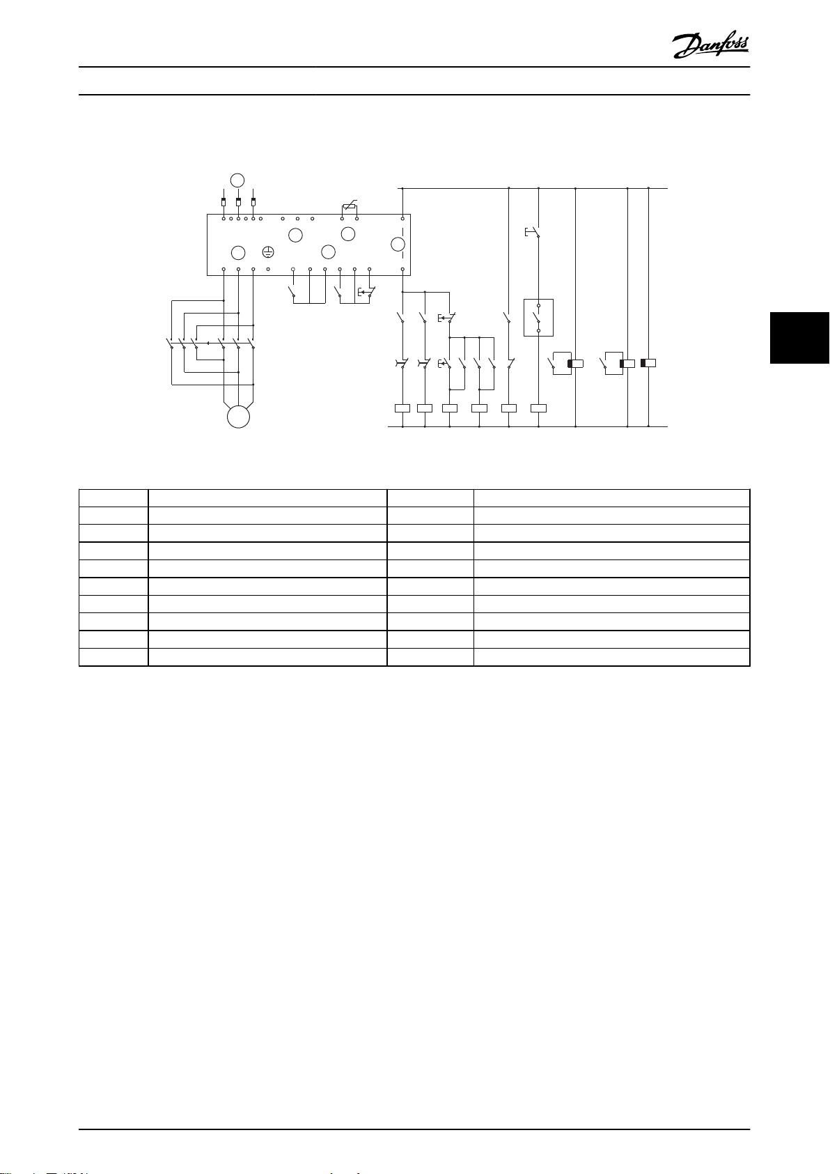
E
1/L1
3/L2
5/L3
2/T1
33
34
A4 A5 A6
05
06
KA3
KA2 S3
53
Application Examples MCD 500 Operating Instruction
Illustration 5.15
5 5
1 Control voltage (model dependent) KA1 Run relay
2 Remote control inputs KA2 Start relay
3 Motor thermistor input (PTC only) KA3 Brake relay
4 Relay outputs KA4 Rotation sensing relay
5 3-phase supply KM1 Line contactor (Run)
6 Motor terminals KM2 Line contactor (Brake)
A2 Shaft rotation sensor KT1 Run delay timer
S1 Start contact KT2 Brake delay timer
S2 Stop contact KT3 Shaft rotation sensor delay timer
S3 Reset contact
Table 5.16
Parameter settings:
3-3 Input A Function
•
Select Motor Set Select - assigns Input A for Motor set selection
•
Set starting performance characteristics using the primary motor set (parameter group 1)
•
Set braking performance characteristics using the secondary motor settings (parameter group 7)
•
4-7 Relay C Function
•
Select Trip - assigns Trip function to Relay Output C
•
NOTE
If the MCD-500 trips on supply frequency (16-5 Frequency) when the braking contactor KM2 opens, modify the setting of
Parameters 2-8 through 2-10.
MG17K402 - VLT® is a registered Danfoss trademark 43
Page 45

Application Examples MCD 500 Operating Instruction
5.14 Two Speed Motor
The MCD 500 can be configured for control of dual speed Dahlander type motors, using a high speed contactor (KM1), low
speed contactor (KM2) and a star contactor (KM3).
NOTE
Pole Amplitude Modulated (PAM) motors alter the speed by effectively changing the stator frequency using external
winding configuration. Soft starters are not suitable for use with this type of two-speed motor.
When the soft starter receives a high speed start signal, it closes the high speed contactor (KM1) and star contactor (KM3),
then controls the motor according to the primary motor settings (parameters 1-1 through 1-16.)
55
When the soft starter receives a low speed start signal, it closes the low speed contactor (KM2). This closes Input A and the
MCD 500 controls the motor according to the secondary motor settings (parameters 7-1 through 7-16).
NOTE
If the MCD 500 trips on supply frequency (16-5 Frequency) when the high-speed start signal (7) is removed, modify the
setting of parameters 2-8 through 2-10.
44 MG17K402 - VLT® is a registered Danfoss trademark
Page 46
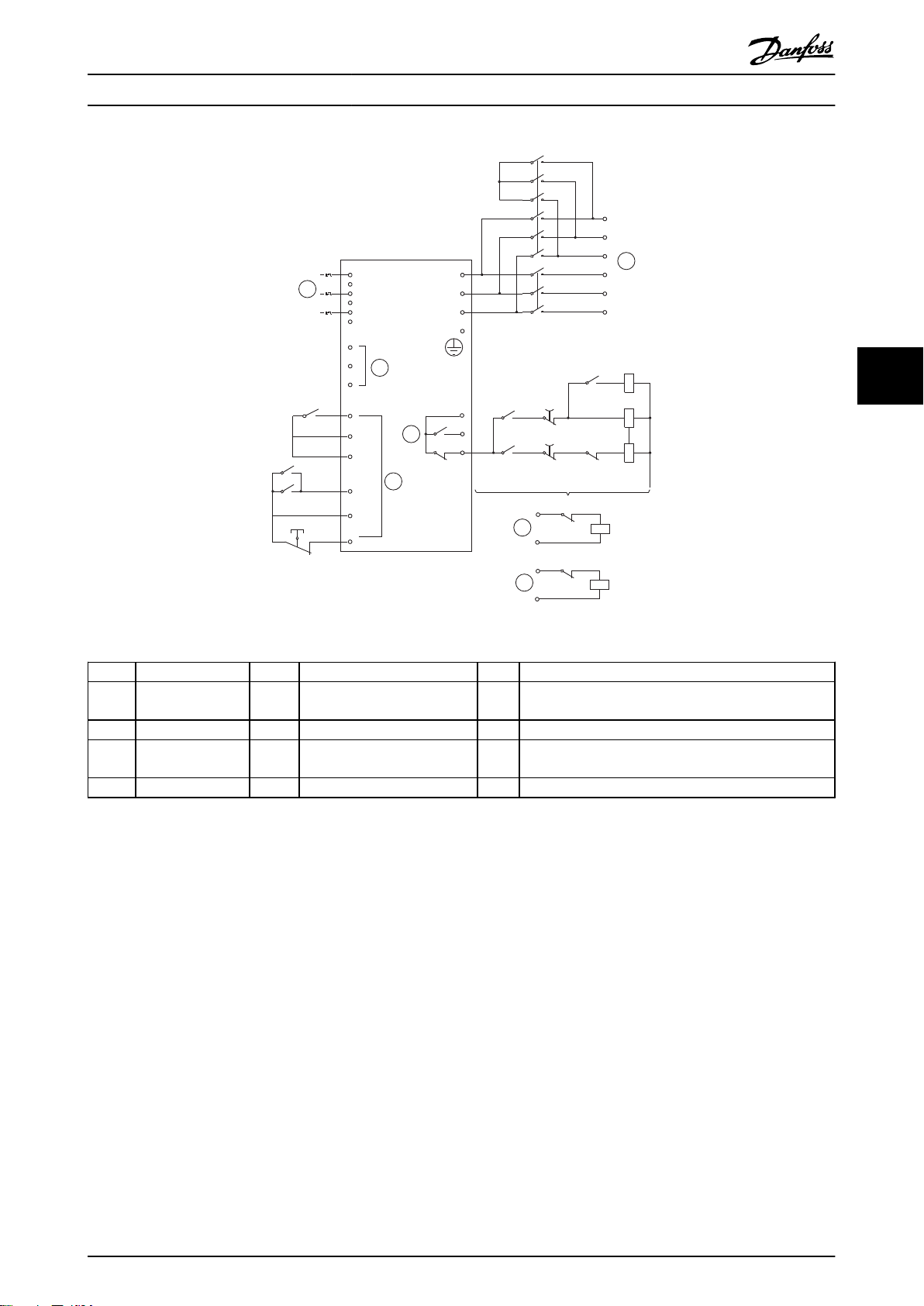
177HA527.10
2/T1
4/T2
6/T3
E
T4
T5
T6
T1
T2
T3
A6
A4
A5
1/L1
3/L2
5/L3
24
22
21
KA1
KA2
KA1
KA2
KM3
KA1
KM2KA2
KM1
KM2
KM3
KM1
KM3
KM1
KM3
KM2
S1
KM2
KM1
KA1
F1
17
18
25
11
16
15
3
6
7
5
4
2
1
Application Examples MCD 500 Operating Instruction
5 5
Illustration 5.16
1
2 Remote control
Control voltage 6 Remote low-speed start input KM2 Line contactor (low speed)
7 Remote high-speed start input KM3 Star contactor (high speed)
inputs
3 Relay outputs KA1 Remote start relay (low speed) S1 Reset contact
4 3-phase supply KA2 Remote start relay (high speed) 21,
Relay output B
22, 24
5 Motor terminals KM1 Line contactor (high speed)
Table 5.17
NOTE
Contactors KM2 and KM3 must be mechanically interlocked.
Parameter settings:
3-3 Input A Function
•
Select Motor Set Select - assigns Input A for Motor set selection
•
•
Set high speed performance characteristics using parameters 1-1 - 2-9
•
Set low speed performance characteristics using parameters 7-1 - 7-16.
•
4-4 Relay B Function
Select Trip - assigns Trip function to Relay Output B
•
MG17K402 - VLT® is a registered Danfoss trademark 45
Page 47
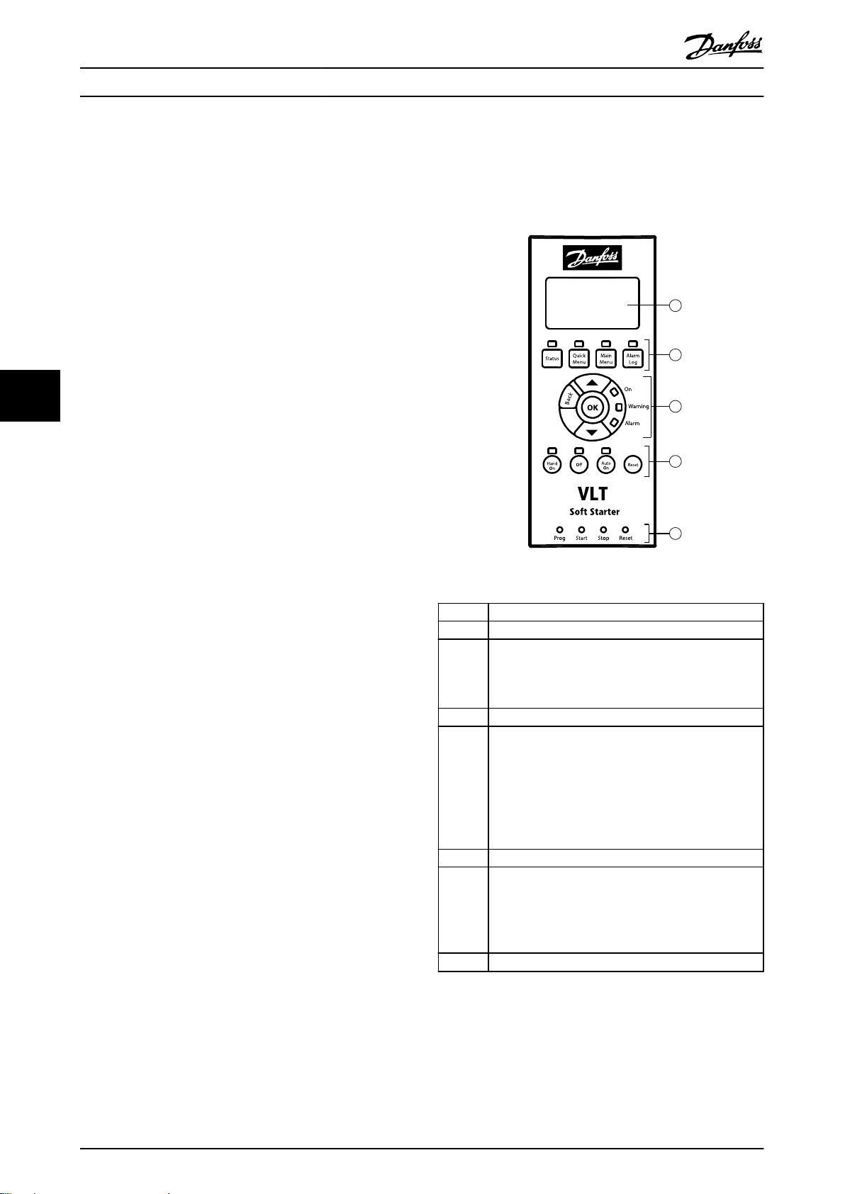
177HA383.10
3
4
5
2
1
®
6
Operation MCD 500 Operating Instruction
6 Operation
6.1.2 The LCP
6.1 Operation and LCP
6.1.1 Operating Modes
In Hand On mode:
To soft start the motor, press [Hand On] on the
•
LCP
To stop the motor, press [Off] on the LCP
•
To reset a trip on the starter, press [Reset] on the
•
LCP
To emergency stop the motor, press the local
•
[Off] and [Reset] buttons at the same time. The
soft starter will remove power from the motor
and open the main contactor, and the motor will
coast to stop. Emergency stop can also be
controlled via a programmable input.
In Auto On mode:
Illustration 6.1
To soft start the motor, activate the Start remote
•
input
To stop the motor, activate the Stop remote
•
input
To reset a trip on the starter, activate the Reset
•
remote input
NOTE
Brake and Jog functions operate only with in-line
connected motors (see Inside Delta Operation)
1 Four-line display for status and programming details.
2 Display control buttons:
Status: Return to the status displays
Quick Menu: Open the Quick Menu
Main Menu: Open the Main Menu
Alarm Log: Open the Alarm Log
3 Menu navigation buttons:
[Back]: Exit the menu or parameter, or cancel a
parameter change
[OK]: Enter a menu or parameter, or save a parameter
change
[▲] [▼]: Scroll to the next or previous menu or
parameter, change the setting of the current
parameter or scroll through the status screens.
4 Soft starter local control buttons:
[Hand On]: Start the motor and enter local control
mode.
[Off]: Stop the motor (only active in Hand On mode).
[Auto On]: Set the starter to Auto On mode.
[Reset]: Reset a trip (Hand On mode only).
5 Remote input status LEDs.
Table 6.1
6.2
46 MG17K402 - VLT® is a registered Danfoss trademark
Remote Mounted LCP
A remote mounted LCP can be installed with the MCD 500.
The Control Panel LCP501 can be mounted up to 3 metres
away from the starter, for control and monitoring.
Page 48
Operation MCD 500 Operating Instruction
The starter can be controlled and programmed from either
the remote LCP or the LCP on the starter. Both displays
show the same information.
6.2.1 Synchronising the LCP and the Starter
The DB9 cable can be connected/disconnected from the
LCP while the starter is running.
The first time a LCP is plugged into a starter, the starter
will copy its parameter settings to the LCP.
New display detected
Table 6.2
If the LCP has previously been used with a MCD 500, the
operator can select whether to copy the parameters to the
starter, or to copy the MCD 500's parameter settings into
the LCP.
Select the required option using the [▲] and [▼] buttons.
The selected option is surrounded by a dotted line. Press
OK to proceed with the selection. Copy Parameters Display
to Starter Starter to Display
Display to starter
Starter to display
Table 6.3
Copy parameters
NOTE
If the parameter software version in the LCP is different
from the software version of the starter, only Starter to
Display will be available.
Ready
Welcome
1.05 / 2.0 / 1.13
MCD5-0053-T5-G1-CV2
Table 6.4
3rd display line: Software versions for Remote LCP, Control software,
Model software
4th display line: Product model number
S1
NOTE
The LCP version is only displayed if a Remote LCP 501 is
connected when control power is applied. If no remote
LCP is present, only the control software and model
software versions will be displayed.
6.4 Control Methods
The MCD 500 can be controlled via the control buttons on
the LCP (local control), via the remote inputs (remote
control) or via the serial communication network.
Local control is only available in Hand On mode.
•
Remote control is only available in Auto On
•
mode.
Control via the serial communication network is
•
always disabled in Hand On mode, and Start/Stop
commands via the serial network may be enabled
or disabled in Auto On mode by changing the
setting of 3-2 Comms in Remote.
The MCD 500 can also be configured to auto-start or autostop. Auto-start/stop operation is only available in Auto On
mode, and must be configured using parameters 5-1 - 5-4.
In Hand On mode, the starter will ignore any auto-start/
stop setting.
To switch between Hand On and Auto On modes, use the
local control buttons on the LCP.
6
6
NOTE
While the LCP is synchronising, only the [▲], [▼], [OK], and
[Off] buttons are enabled.
6.3 Welcome Screen
When control power is applied, the starter will display the
welcome screen
MG17K402 - VLT® is a registered Danfoss trademark 47
[Hand On]: Start the motor and enter Hand On mode.
[Off]: Stop the motor and enter Hand On mode.
[Auto On]: Set the starter to Auto On mode.
[Reset]: Reset a trip (Hand On mode only).
The MCD 500 can also be set to allow local control only or
remote control only, using 3-1 Local/Remote.
If 3-1 Local/Remote is set to Remote Control Only, the [Off]
button is disabled and the motor must be stopped by
remote control or via the serial communication network.
Page 49
Operation MCD 500 Operating Instruction
Hand On mode Auto On mode
To soft start the motor press [Hand On] on the LCP activate the Start remote input
To stop the motor press [Off] on the LCP activate the Stop remote input
To reset a trip on the starter press [Reset] on the LCP activate the Reset remote input
Auto start/stop operation Disabled Enabled
Table 6.5
To emergency stop the motor, press the local [Off] and [Reset] buttons at the same time. The soft starter will remove power
from the motor and open the main contactor, and the motor will coast to stop. Emergency stop can also be controlled via a
programmable input.
NOTE
Brake and Jog functions operate only with in-line connected motors (see 5.6 Inside Delta Operation)
6
6.5 Local Control Buttons
If 3-1 Local/Remote is set to LCL/RMT Anytime or LCL/RMT
When OFF, the [Hand On] and [Auto On] buttons are
always active. If the MCD 500 is in Auto On mode, pressing
[Hand On] will enter Hand On mode and start the motor.
If 3-1 Local/Remote is set to Remote Control Only, the [Off]
button is disabled and the motor must be stopped by
remote control or via the serial communication network.
6.6 Displays
The LCP displays a wide range of performance information
about the soft starter. Press [Status] to access the status
display screens, then use [▲] and [▼] to select the
information to display. To return to the status screens from
within a menu, press [Back] repeatedly or press [Status].
Temperature monitoring
•
Programmable screen (see parameters 8-2 - 8-5)
•
Current
•
Frequency
•
Motor power
•
Last start information
•
Date and time
•
SCR Conduction bar-graph
•
Performance graphs
•
NOTE
Screens shown here are with the default settings.
The temperature monitoring screen is the default status
screen.
Ready S1
MS1 000.0A 000.0kW
Primary Motor Set
M1 000%
Table 6.6
6.6.2 Programmable Screen (S2)
The MCD 500's user-programmable screen can be
configured to show the most important information for the
particular application. Use parameters 8-2 to 8-5 to select
which information to display.
Ready S2
MS1 000.0A 000.0kW
-.-- pf
00000 hrs
Table 6.7
Average Current (S3)
6.6.3
The average current screen shows the average current of
all three phases.
Ready
MS1 000.0A 000.0kW
0.0A
Table 6.8
S3
6.6.1 Temperature Monitoring Screen (S1)
The temperature screen shows the temperature of the
motor as a percentage of total thermal capacity, and also
shows which motor data set is in use.
48 MG17K402 - VLT® is a registered Danfoss trademark
Page 50
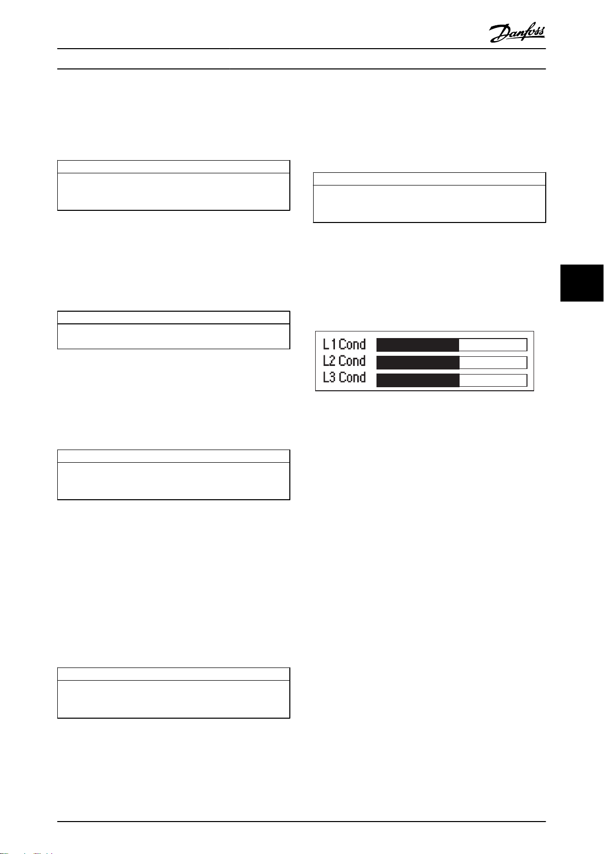
177HA513.10
Operation MCD 500 Operating Instruction
6.6.4 Current Monitoring Screen (S4)
The current screen shows real-time line current on each
phase.
Ready S4
MS1 000.0A 000.0kW
Phase currents
000.0A 000.0A 000.0A
Table 6.9
6.6.5 Frequency Monitoring Screen (S5)
The frequency screen shows the mains frequency as
measured by the soft starter.
Ready S5
MS1 000.0A 000.0kW
00.0Hz
Table 6.10
Motor Power Screen (S6)
6.6.6
The motor power screen shows motor power (kW, HP and
kVA) and power factor.
Ready
MS1 000.0A 000.0kW
000.0kW 0000HP
0000kVA -. - - pf
Table 6.11
Last Start Information (S7)
6.6.7
The last start information screen shows details of the most
recent successful start:
start duration (seconds)
•
maximum start current drawn (as a percentage of
•
motor full load current)
calculated rise in motor temperature
•
Ready
MS1 000.0A 000.0kW
Last start 000 s
000 % FLC
S6
S7
ΔTemp 0%
6.6.8
Date and Time (S8)
The date/time screen shows the current system date and
time (24 hour format). For details on setting the date and
time, see 8.1 Set Date and Time.
Ready S8
MS1 000.0A 000.0kW
YYYY MMM DD
HH:MM:SS
Table 6.13
SCR Conduction Bargraph
6.6.9
The SCR conduction bargraph shows the level of
conduction on each phase.
Illustration 6.2
6.6.10 Performance Graphs
The MCD 500 can display real-time performance
information for:
Current
•
Motor temperature
•
Motor kW
•
Motor kVA
•
Motor power factor
•
The newest information is displayed at the right hand
edge of the screen. Older data is not stored. The graph can
also be paused, to allow past performance to be analysed.
To pause or unpause the graph, press and hold [OK] for
more than 0.5 seconds.
NOTE
The MCD 500 will not collect data while the graph is
paused. When graphing resumes, a small gap will be
shown between the old data and the new data.
6
6
Table 6.12
MG17K402 - VLT® is a registered Danfoss trademark 49
Page 51
Programming MCD 500 Operating Instruction
7 Programming
It is possible to access the programming menus at any
time, including while the soft starter is running. All
changes take effect immediately.
7.1 Access Control
Critical parameters (parameter group 15 and higher) are
protected by a four-digit security access code, preventing
unauthorised users from viewing or modifying parameter
settings.
When a user attempts to enter a restricted parameter
group, the LCP prompts for an access code. The access
code is requested once for the programming session, and
77
authorisation continues until the user closes the menu.
To enter the access code, press [Back] and [OK] to select a
digit, and [▲] and [▼] to change the value. When all four
digits match the access code, press [OK]. The LCP will
display an acknowledgement message before continuing.
To change the access code, use 15-1 Access Code.
Enter Access Code
####
OK
Access Allowed
SUPERVISOR
Table 7.1
NOTE
The protection simulation and output simulation are also
protected by the security access code. The counters and
thermal model reset can be viewed without entering an
access code, but an access code must be entered in order
to reset.
The default access code is 0000.
Lock the menus to prevent users from altering parameter
settings. The adjustment lock can be set to allow Read &
Write, Read Only or No Access in 15-2 Adjustment Lock.
If a user attempts to change a parameter value or access
the Main Menu when the adjustment lock is active, an
error message is displayed:
Access Denied
Adj Lock is On
Table 7.2
50 MG17K402 - VLT® is a registered Danfoss trademark
Page 52
Programming MCD 500 Operating Instruction
7.2 Quick Menu
7.2.1 Quick Setup
Quick setup provides access to commonly used parameters, allowing the user to configure the MCD 500 as required for the
application. For details of individual parameters, see Parameter Descriptions.
1 Primary Mtr Set
1-1 Motor FLC
1-3 Start Mode
1-4 Current Limit
1-5 Initial Current
1-6 Start Ramp Time
1-9 Excess Start Time
1-10 Stop Mode
1-11 Stop Time
2 Protection
2-1 Phase Sequence
2-4 Undercurrent
2-5 Undercurrent Dly
2-6 Inst Overcurrent
2-7 Inst Overcurrent Dly
3 Inputs
3-3 Input A Function
3-4 Input A Name
3-5 Input A Trip
3-6 Input A Trip Dly
3-7 Input A Initial Dly
4 Outputs
4-1 Relay A Function
4-2 Relay A On Delay
4-3 Relay A Off Delay
4-4 Relay B Function
4-5 Relay B On Delay
4-6 Relay B Off Delay
4-7 Relay C Function
4-8 Relay C On Delay
4-9 Relay C Off Delay
4-10 Low Current Flag
4-11 High Current FLag
4-12 Motor Temp Flag
5 Start/Stop Timers
5-1 Auto-Start Type
5-2 Auto-Start Time
5-3 Auto-Stop Type
5-4 Auto-Stop Time
8 Display
8-1 Language
8-2 User Scrn Top L
8-3 User Scrn Top R
8-4 User Scrn Btm L
8-5 User Scrn Btm R
7 7
Table 7.3
MG17K402 - VLT® is a registered Danfoss trademark 51
Page 53
Programming MCD 500 Operating Instruction
7.2.2 Application Setups
The application setups menu makes it easy to configure the MCD 500 for common applications. The MCD 500 selects the
parameters relevant to the application and suggests a typical setting, and you can adjust each parameter to suit your exact
requirements.
On the display the highlighted values are suggested values and the values indicated by a ▶ are the loaded values.
Always set 1-1 Motor FLC to match the motor's nameplate full load current. The suggested value for motor FLC is the
starter's minimum FLC.
Pump Centrifugal Suggested Value Compressor Recip Suggested Value
Motor Full Load Current Motor Full Load Current
Start Mode
Adaptive Start Profile
Start Ramp Time
Stop Mode
77
Adaptive Stop Profile
Stop Time
Pump Submersible Conveyor
Motor Full Load Current Motor Full Load Current
Start Mode
Adaptive Start Profile
Start Ramp Time
Stop Mode
Adaptive Stop Profile
Stop Time
Fan Damped Crusher Rotary
Motor Full Load Current Motor Full Load Current
Start Mode
Current Limit
Fan Undamped Crusher Jaw
Motor Full Load Current Motor Full Load Current
Start Mode
Adaptive Start Profile
Start Ramp Time
Excess Start Time
Locked Rotor Time
Compressor Screw
Motor Full Load Current
Start Mode
Start Ramp Time
Current Limit
Adaptive Control
Early Acceleration
10 seconds
Adaptive Control
Late Deceleration
15 seconds
Adaptive Control
Early Acceleration
5 seconds
Adaptive Control
Late Deceleration
5 seconds
Constant Current
350%
Adaptive Control
Constant Acceleration
20 seconds
30 seconds
20 seconds
Constant Current
5 seconds
400%
Start Mode
Start Ramp Time
Current Limit
Start Mode
Start Ramp Time
Current Limit
Stop Mode
Adaptive Stop Profile
Stop Time
Start Mode
Start Ramp Time
Current Limit
Excess Start Time
Locked Rotor Time
Start Mode
Start Ramp Time
Current Limit
Excess Start Time
Locked Rotor Time
Constant Current
10 seconds
450%
Constant Current
5 seconds
400%
Adaptive Control
Constant Deceleration
10 seconds
Constant Current
10 seconds
400%
30 seconds
20 seconds
Constant Current
10 seconds
450%
40 seconds
30 seconds
Table 7.4
52 MG17K402 - VLT® is a registered Danfoss trademark
Page 54
Programming MCD 500 Operating Instruction
7.2.3 Loggings
The Loggings menu allows the user to view performance
information in real-time graphs.
Current (%FLC)
•
Motor Temp (%)
•
Motor kW (%)
•
Motor kVA (%)
•
Motor pf
•
The newest information is displayed at the right hand
edge of the screen. The graph can be paused to analyse
data by pressing and holding the [OK] button. To re-start
the graph, press and hold [OK].
7.3 Main Menu
The Main Menu button provides access to menus for
setting up the MCD 500 for complex applications and for
monitoring its performance.
Parameters
7.3.1
Parameters allows viewing and changing all programmable
parameters that control how the MCD 500 operates.
To open Parameters, press [Main Menu] then select
Parameters.
To navigate through Parameters:
to scroll through parameter groups, press [▲] or
•
[▼].
to view the parameters in a group, press [OK].
•
to return to the previous level, press [Back].
•
to close Parameters, press the [Back].
•
To change a parameter value:
scroll to the appropriate parameter and press
•
[OK] to enter edit mode.
to alter the parameter setting, use the [▲] and [▼]
•
buttons.
to save changes, press [OK]. The setting shown
•
on the display will be saved and the LCP will
return to the parameter list.
to cancel changes, press [Back]. The LCP will
•
return to the parameter list without saving
changes.
Parameter Shortcut
7.3.2
The MCD 500 also includes a parameter shortcut, which
allows you to directly access a parameter within the
Parameters menu.
To access the parameter shortcut, press [Main
•
Menu] for three seconds
Use [▲] or [▼] to select the parameter group.
•
Press [OK] or [Back] to move the cursor.
•
Use [▲] or [▼] to select the parameter number.
•
Parameter shortcut
Please enter a
Parameter number
01-01
Table 7.5
7 7
MG17K402 - VLT® is a registered Danfoss trademark 53
Page 55
Programming MCD 500 Operating Instruction
7.3.3 Parameter List
1 Primary Mtr Set 4 Outputs 7-12 Adaptv Ctrl Gain-2
1-1 Motor FLC 4-1 Relay A Function 7-13 Adaptv Start Prof-2
1-2 Locked Rotor Time 4-2 Relay A On Delay 7-14 Adaptv Stop Prof-2
1-3 Start Mode 4-3 Relay A Off Delay 7-15 Brake Torque-2
1-4 Current Limit 4-4 Relay B Function 7-16 Brake Time-2
1-5 Initial Current 4-5 Relay B On Delay 8 Display
1-6 Start Ramp Time 4-6 Relay B Off Delay 8-1 Language
1-7 Kickstart Level 4-7 Relay C Function 8-2 User Scrn Top L
1-8 Kickstart Time 4-8 Relay C On Delay 8-3 User Scrn Top R
1-9 Excess Start Time 4-9 Relay C Off Delay 8-4 User Scrn Btm L
1-10 Stop Mode 4-10 Low Current Flag 8-5 User Scrn Btm R
1-11 Stop Time 4-11 High Current FLag 8-6 Graph Timebase
1-12 Adaptv Control Gain 4-12 Motor Temp Flag 8-7 Graph Max Adj
1-13 Adaptv Start Profile 4-13 Analog Output A 8-8 Graph Min Adj
1-14 Adaptv Stop Profile 4-14 Analog A Scale 8-9 Mains Ref Volt
77
1-15 Brake Torque 4-15 Analog A Max Adj 15 Restrict Paramtr
1-16 Brake Time 4-16 Analog A Min Adj 15-1 Access Code
2 Protection 5 Start/Stop Timers 15-2 Adjustment Lock
2-1 Phase Sequence 5-1 Auto-Start Type 15-3 Emergency Run
2-2 Current Imbalance 5-2 Auto-Start Time 15-4 Current Calibrat
2-3 Current Imbal Dly 5-3 Auto-Stop Type 15-5 Main Cont Time
2-4 Undercurrent 5-4 Auto-Stop Time 15-6 Bypass Cont Time
2-5 Undercurrent Dly 6 Auto-Reset 15-7 Motor Connection
2-6 Inst Overcurrent 6-1 Auto-Reset Action 15-8 Jog Torque
2-7 Inst Ocrnt Dly 6-2 Maximum Resets 16 Protection Action
2-8 Frequency Check 6-3 Reset Dly Grp A & B 16-1 Motor Overload
2-9 Freq Variation 6-4 Reset Delay Grp C 16-2 Current Imbalance
2-10 Frequency Delay 7 Secondary Mtr Set 16-3 Undercurrent
2-11 Restart Delay 7-1 Motor FLC-2 16-4 Inst Overcurrent
2-12 Motor Temp Check 7-2 Lock Rotor Time-2 16-5 Frequency
3 Inputs 7-3 Start Mode-2 16-6 Heatsink Overtemp
3-1 Local/Remote 7-4 Current Limit-2 16-7 Excess Start Time
3-2 Comms in Remote 7-5 Initial Crnt-2 16-8 Input A Trip
3-3 Input A Function 7-6 Start Ramp-2 16-9 Motor Thermistor
3-4 Input A Name 7-7 Kickstart Lvl-2 16-10 Starter Comms
3-5 Input A Trip 7-8 Kickstart Time-2 16-11 Network Comms
3-6 Input A Trip Dly 7-9 Excess Strt Time-2 16-12 Battery/Clock
3-7 Input A Initial Dly 7-10 Stop Mode-2 16-13 Low Control Volts
3-8 Remote Reset Logic 7-11 Stop Time-2
Table 7.6
54 MG17K402 - VLT® is a registered Danfoss trademark
Page 56
Programming MCD 500 Operating Instruction
7.4 Primary Motor Settings
NOTE
Default settings are marked with *.
The parameters in Primary Motors Settings configure the
soft starter to match the connected motor. These
parameters describe the motor's operating characteristics
and allow the soft starter to model the motor's
temperature.
1-1 Motor FLC
Option: Function:
Model
dependent
Matches the starter to the connected motor's
full load current. Set to the full load current
(FLC) rating shown on the motor nameplate.
1-2 Locked Rotor Time
Range: Function:
10 secs* [0:01 - 2:00
(min:sec)]
Sets the maximum length of the time
the motor can run at locked rotor
current from cold before reaching its
maximum temperature. Set according
to the motor datasheet.
If this information is not available, we
recommend the value should be less
than 20 seconds.
1-3 Start Mode
Option: Function:
Selects the soft start mode. See 5.3 Starting
Modes for more details.
Constant Current*
Adaptive Control
1-4 Current Limit
Range: Function:
350%* [100% -
600% FLC]
Sets the current limit for constant current
and current ramp soft starting, as a
percentage of motor full load current.
See 5.3 Starting Modes for more details.
1-5 Initial Current
Range: Function:
350%* [100% -
600% FLC]
Sets the initial start current level for current
ramp starting, as a percentage of motor full
load current. Set so that the motor begins to
accelerate immediately after a start is
initiated.
If current ramp starting is not required, set
the initial current equal to the current limit.
See 5.3 Starting Modes for more details.
1-6 Start Ramp Time
Range: Function:
10 secs* [1 - 180
secs]
Sets the total start time for an AAC
Adaptive Control start or the ramp time
for current ramp starting (from the initial
current to the current limit). See
5.3 Starting Modes for more details.
1-7 Kickstart Level
Range: Function:
500%* [100% -
700% FLC]
Sets the level of the kickstart current.
CAUTION
Kickstart subjects the mechanical
equipment to increased torque levels.
Ensure the motor, load and couplings
can handle the additional torque
before using this feature.
1-8 Kickstart Time
Range: Function:
0000
msecs*
[0 - 2000
msecs]
Sets the kickstart duration. A setting of 0
disables kickstart. See 5.3 Starting Modes
for more details.
CAUTION
Kickstart subjects the mechanical
equipment to increased torque
levels. Ensure the motor, load and
couplings can handle the additional
torque before using this feature.
1-9 Excess Start Time
Range: Function:
Excess start time is the maximum time
the MCD 500 will attempt to start the
motor. If the motor does not reach full
speed within the programmed limit, the
starter will trip. Set for a period slightly
longer than required for a normal
healthy start. A setting of 0 disables
excess start time protection.
20
secs*
1-10 Stop Mode
Option: Function:
[0:00 - 4:00
(min:secs)]
Coast to Stop*
TVR Soft Stop
Set as required.
Selects the stop mode. See 5.4 Stopping
Modes for more details.
7 7
MG17K402 - VLT® is a registered Danfoss trademark 55
Page 57
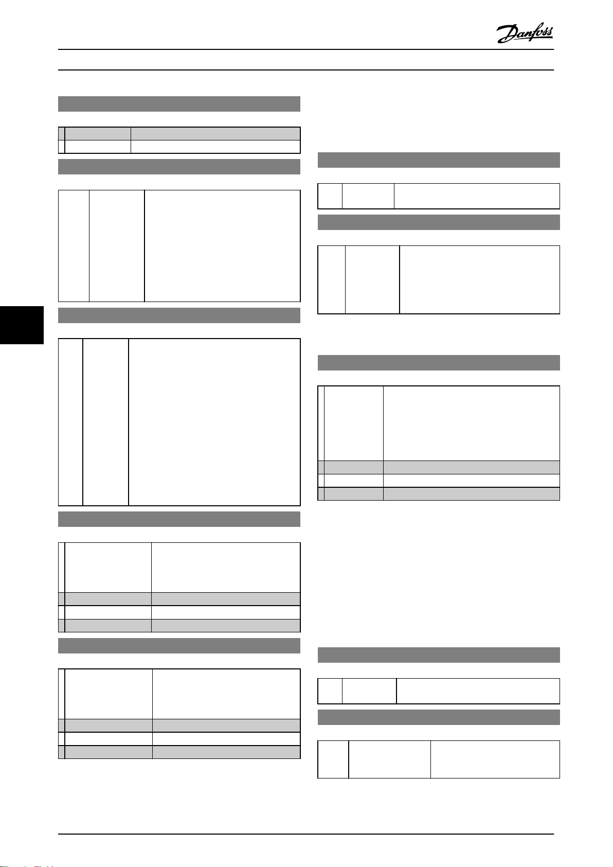
Programming MCD 500 Operating Instruction
1-10 Stop Mode
7.4.1 Brake
Option: Function:
Adaptive Control
Brake
1-11 Stop Time
Range: Function:
0 secs* [0:00 - 4:00
(min:secs)]
Sets the time for soft stopping the motor
using timed voltage ramp or Adaptive
Control (AAC). If a main contactor is
installed, the contactor must remain
closed until the end of the stop time. Use
a programmable output configured to
Run to control the main contactor. Sets
the toal stopping time when using brake.
See 5.4 Stopping Modes for more details.
Brake uses DC injection to actively slow the motor. See
5.4 Stopping Modes for more details.
1-15 Brake Torque
Range: Function:
20%* [20 - 100%] Sets the amount of brake torque the MCD
500 will use to slow the motor.
1-16 Brake Time
Range: Function:
1 sec* [1 - 30 secs] Sets the duration for DC injection during a
braking stop.
NOTE
This parameter is used in conjunction
with 1-11 Stop Time. See for details.
1-12 Adaptive Control Gain
77
Range: Function:
75%* [1% -
200%]
Adjusts the performance of AAC adaptive
acceleration control. This setting affects both
starting and stopping control.
NOTE
We recommend leaving the gain setting
at the default level unless AAC
performance is not satisfactory. If the
motor accelerates or decelerates quickly
at the end of a start or stop, increase the
gain setting by 5%~10%. If the motor
speed fluctuates during starting or
stopping, decrease the gain setting
slightly.
7.5 Protection
2-1 Phase Sequence
Option: Function:
Selects which phase sequences the soft starter
will allow at a start. During its pre-start checks,
the starter examines the sequence of the
phases at its input terminals and trips of the
actual sequence does not match the selected
option.
Any sequence*
Positive only
Negative only
1-13 Adaptive Start Profile
Option: Function:
Selects which profile the MCD 500 will
use for an AAC adaptive acceleration
control soft start. See 5.4 Stopping
Modes for more details.
Early Acceleration
Constant Acceleration*
Late Acceleration
1-14 Adaptive Stop Profile
Option: Function:
Selects which profile the MCD 500 will
use for an AAC adaptive acceleration
control soft stop. See 5.4 Stopping
Modes for more details.
Early Deceleration
Constant Deceleration*
Late Acceleration
7.5.1 Current Imbalance
The MCD 500 can be configured to trip if the currents on
the three phases vary from each other by more than a
specified amount. The imbalance is calculated as the
difference between the highest and lowest currents on all
three phases, as a percentage of the highest current.
Current imbalance detection is desensitised by 50% during
starting and soft stopping.
2-2 Current Imbalance
Range: Function:
30%* [10% - 50%] Sets the trip point for current imbalance
protection.
2-3 Current Imbalance Delay
Range: Function:
3 secs* [0:00 - 4:00
(min:secs)]
Slows the MCD 500's response to
current imbalance, avoiding trips
due to momentary fluctuations.
56 MG17K402 - VLT® is a registered Danfoss trademark
Page 58
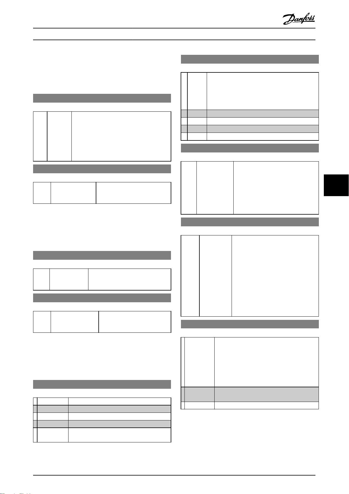
Programming MCD 500 Operating Instruction
7.5.2 Undercurrent
The MCD 500 can be configured to trip if the average
current of all three phases drops below a specified level
while the motor is running.
2-4 Undercurrent
Range: Function:
20%* [0% -
100%]
Sets the trip point for undercurrent protection,
as a percentage of motor full load current. Set
to a level between the motor's normal working
range and the motor's magnetising (no load)
current (typically 25% to 35% of full load
current). A setting of 0% disables undercurrent
protection.
2-5 Undercurrent Delay
Range: Function:
5 secs* [0:00 - 4:00
(min:secs)]
Slows the MCD 500's response to
undercurrent, avoiding trips due to
momentary fluctuations.
7.5.3 Instantaneous Overcurrent
The MCD 500 can be configured to trip if the average
current of all three phases exceeds a specified level while
the motor is running.
2-6 Instantaneous Overcurrent
Range: Function:
400%* [80% - 600%
FLC]
Sets the trip point for instantaneous
overcurrent protection, as a
percentage of motor full load current.
2-7 Instantaneous Overcurrent Delay
Range: Function:
0 secs* [0:00 - 1:00
(min:secs)]
Slows the MCD 500's response to
overcurrent, avoiding trips due to
momentary overcurrent events.
7.5.4 Frequency Trip
The MCD 500 monitors mains frequency throughout
operation, and can be configured to trip is the frequency
varies beyond a specified tolerance.
2-8 Frequency Check
Option: Function:
Do not Check
Start Only
Start/Run*
Run Only
Determines when the starter will monitor for a
frequency trip.
2-9 Frequency Variation
Option: Function:
Selects the soft starter's tolerance for frequency
variation.
Running a motor outside its specified frequency for
long periods can cause damage and premature
failure.
± 2 Hz
± 5 Hz*
± 10 Hz
± 15 Hz
2-10 Frequency Delay
Range: Function:
1 sec* [0:01 - 4:00
(min:sec)]
Slows the MCD 500's response to
frequency disturbances, avoiding trips
due to momentary fluctuations.
NOTE
If the mains frequency drops below
35 Hz or rises above 75 Hz, the
starter will trip immediately.
2-11 Restart Delay
Range: Function:
10
secs*
[00:01 60:00
(min:secs)]
The MCD 500 can be configured to force
a delay between the end of a stop and
the beginning of the next start. During
the restart delay, the display shows the
time remaining before another start can
be attempted.
NOTE
The restart delay is measured from
the end of each stop. Changes to
the restart delay setting take effect
immediately.
2-12 Motor Temperature Check
Option: Function:
Selects whether the MCD 500 will verify the
motor has sufficient thermal capacity for a
successful start. The soft starter compares the
motor's calculated temperature with the
temperature rise from the last motor start and
only operates if the motor is cool enough to start
successfully.
Do not
Check*
Check
7 7
MG17K402 - VLT® is a registered Danfoss trademark 57
Page 59
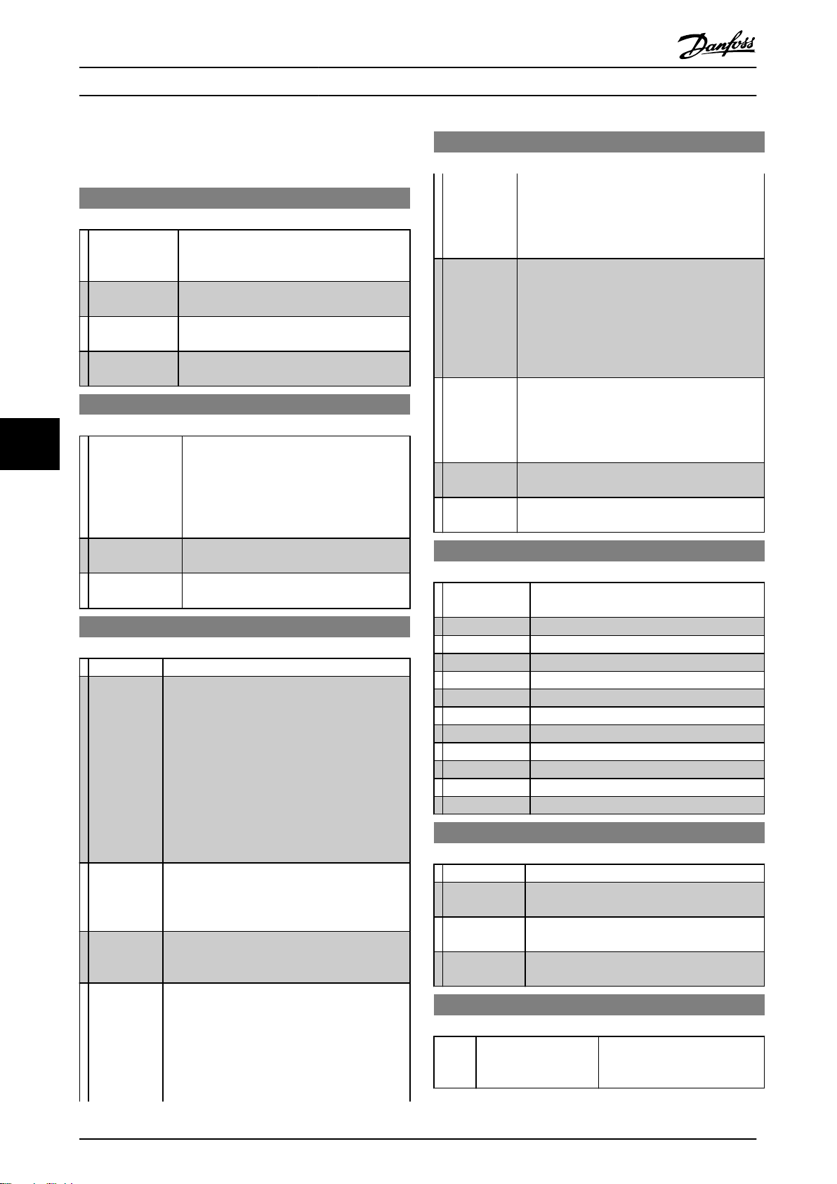
Programming MCD 500 Operating Instruction
3-3 Input A Function
7.6 Inputs
3-1 Local/Remote
Option: Function:
Selects when the [Auto On] and [Hand On]
buttons can be used to switch to Hand On or
Auto On modes.
Lcl/Rmt
anytime*
Local Control
Only
Remote Control
Only
3-2 Comms in Remote
Option: Function:
77
Disable Ctrl in
RMT
Enable Ctrl in
RMT*
3-3 Input A Function
Option: Function:
Motor Set
Select*
Input Trip
(N/O)
Input Trip
(N/C)
Local/Remote
Select
The user can change between local and
remote control at any time.
All remote inputs are disabled.
Selects whether the starter can be used in
Hand On or Auto On modes.
Selects whether the starter will accept Start
and Stop commands from the serial
communication network when in Remote
mode. The Force Comms Trip, Local/Remote
Control and Test Start and Reset commands
are always enabled.
Selects the function of Input A.
The MCD 500 can be configured with two
separate sets of motor data. The primary motor
data is programmed using Parameters 1-1 to
1-16. The secondary motor data is programmed
using Parameters 7-1 to 7-16.
To use the secondary motor data, this parameter
must be set to Motor Set Select and 11, 16 must
be closed when a start command is given. The
MCD 500 checks which motor data to use at a
start, and will use that motor data for the entire
start/stop cycle.
Input A can be used to trip the soft starter.
When this parameter is set to Input Trip (N/O), a
closed circuit across 11, 16 trips the soft starter
(Parameters 3-5, 3-6, 3-7).
When this parameter is set to Input Trip (N/C), an
open circuit across 11, 16 trips the soft starter
(Parameters 3-5, 3-6, 3-7).
Input A can be used to select between local and
remote control, instead of using the buttons on
theLCP. When the input is open, the starter is in
local mode and can be controlled via the LCP.
When the input is closed, the starter is in
remote mode. The [Hand On] and [Auto On]
buttons are disabled, and the soft starter will
Option: Function:
ignore any Local/Remote select command from
the serial communications network.
To use Input A to select between local and
remote control, 3-1 Local/Remote must be set to
LCL/RMT Anytime.
Emergency
Run
Emergency
Stop
Jog Forward Activates jog operation in a forward direction
Jog Reverse Activates jog operation in reverse direction (will
In emergency run the soft starter continues to
run until stopped, ignoring all trips and
warnings (see 15-3 Emergency Run for details).
Closing the circuit across 11, 16 activates
emergency run.
Opening the circuit ends emergency run and the
MCD 500 stops the motor.
The MCD 500 can be commanded to emergency
stop the motor, ignoring the soft stop mode set
in 1-10 Stop Mode.
When the circuit across 11, 16 is opened, the
soft starter allows the motor to coast to stop.
(will operate only in Remote mode).
operate only in Remote mode).
3-4 Input A Name
Option: Function:
Selects a message for the LCP to display
when Input A is active.
Input Trip*
Low Pressure
High Pressure
Pump Fault
Low Level
High Level
No Flow
Emergency Stop
Controller
PLC
Vibration Alarm
3-5 Input A Trip
Option: Function:
Selects when an input trip can occur.
Always Active*
Operating Only A trip can occur while the soft starter is
Run Only A trip can only occur while the soft starter is
A trip can occur at any time when the soft
starter is receiving power.
running, stopping or starting.
running.
3-6 Input A Trip Delay
Range: Function:
0 secs* [0:00 - 4:00 (min:secs)] Sets delay between the input
activating and soft starter
tripping.
58 MG17K402 - VLT® is a registered Danfoss trademark
Page 60
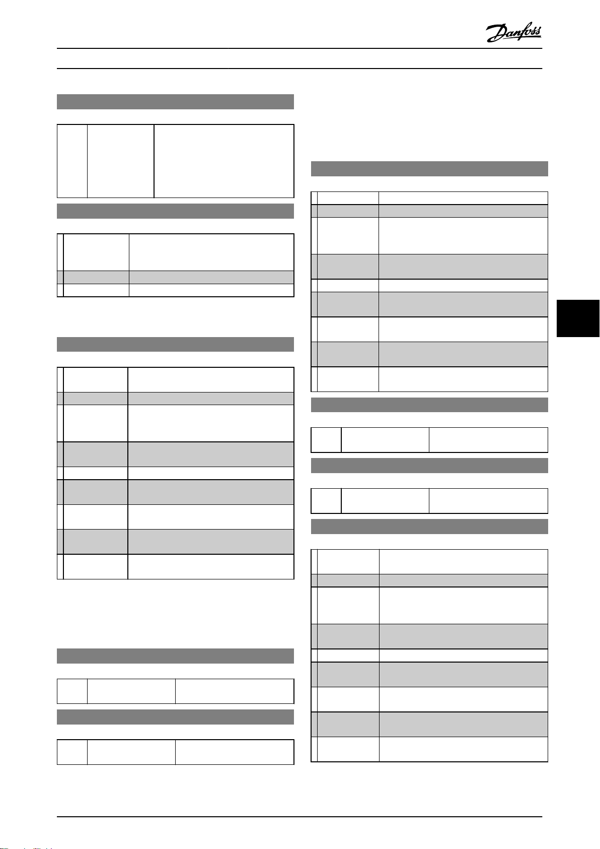
Programming MCD 500 Operating Instruction
3-7 Input A Initial Delay
Range: Function:
0 secs* [00:00 - 30:00
(min:secs)]
Sets a delay before an input trip can
occur. The initial delay is counted
from the time a start signal is
received. The state of the input is
ignored until the initial delay has
elapsed.
3-8 Remote Reset Logic
Option: Function:
Selects whether the MCD 500's remote reset
input (terminals 25, 18) is normally open or
normally closed.
Normally Closed*
Normally Open
7.7 Outputs
4-1 Relay A Function
Option: Function:
Selects the function of Relay A (normally
open).
Off Relay A is not used
Main Contactor*
Run The relay closes when the starter changes to
Trip The relay closes when the starter trips.
Warning The relay closes when the starter issues a
Low Current
Flag
High Current
Flag
Motor Temp
Flag
The relay closes when the MCD 500 receives
a start command, and remains closed as long
as the motor is receiving voltage.
run state.
warning.
The relay closes when the low current flag
activates (4-10 Low Current Flag).
The relay closes when the high current flag
activates (4-11 High Current Flag).
The relay closes when the motor temperature
flag activates (4-12 Motor Temperature Flag).
7.7.1 Relay A Delays
The MCD 500 can be configured to wait before opening or
closing Relay A.
4-2 Relay A On Delay
Range: Function:
0 secs* [0:00 - 5:00 (min:secs)] Sets the delay for closing Relay
A.
4-3 Relay A Off Delay
Range: Function:
0 secs* [0:00 - 5:00 (min:secs)] Sets the delay for re-opening
Relay A.
7.7.2 Relays B and C
Parameters 4-4 to 4-9 configure the operation of Relays B
and C in the same way as parameters 4-1 to 4-3 configure
Relay A.
4-4 Relay B Function
Option: Function:
Selects the function of Relay B (changeover).
Off Relay B is not used
Main Contactor The relay closes when the MCD 500 receives a
start command, and remains closed as long as
the motor is receiving voltage.
Run*
Trip The relay closes when the starter trips.
Warning The relay closes when the starter issues a
Low Current
Flag
High Current
Flag
Motor Temp
Flag
4-5 Relay B On Delay
Range: Function:
0 secs* [0:00 - 5:00 (min:secs)] Sets the delay for closing Relay
4-6 Relay B Off Delay
Range: Function:
0 secs* [0:00 - 5:00 (min:secs)] Sets the delay for re-opening
4-7 Relay C Function
Option: Function:
Off Relay C is not used
Main Contactor The relay closes when the MCD 500 receives a
Run The relay closes when the starter changes to
Trip*
Warning The relay closes when the starter issues a
Low Current
Flag
High Current
Flag
Motor Temp
Flag
The relay closes when the starter changes to
run state.
warning.
The relay closes when the low current flag
activates (4-10 Low Current Flag).
The relay closes when the high current flag
activates (4-11 High Current Flag).
The relay closes when the motor temperature
flag activates (4-12 Motor Temperature Flag).
B.
Relay B.
Selects the function of Relay C (normally
open).
start command, and remains closed as long as
the motor is receiving voltage.
run state.
The relay closes when the starter trips.
warning.
The relay closes when the low current flag
activates (4-10 Low Current Flag).
The relay closes when the high current flag
activates (4-11 High Current Flag).
The relay closes when the motor temperature
flag activates (4-12 Motor Temperature Flag).
7 7
MG17K402 - VLT® is a registered Danfoss trademark 59
Page 61
Programming MCD 500 Operating Instruction
4-8 Relay C On Delay
Range: Function:
0 secs* [0:00 - 5:00 (min:secs)] Sets the delay for closing Relay
C.
4-9 Relay C Off Delay
Range: Function:
0 secs* [0:00 - 5:00 (min:secs)] Sets the delay for re-opening
Relay C.
7.7.3 Low Current Flag and High Current
Flag
The MCD 500 has low and high current flags to give early
warning of abnormal operation. The current flags can be
configured to indicate an abnormal current level during
operation, between the normal operating level and the
77
undercurrent or instantaneous overcurrent trip levels. The
flags can signal the situation to external equipment via
one of the programmable outputs. The flags clear when
the current returns within the normal operating range by
10% of the programmed motor full load current.
4-10 Low Current Flag
Range: Function:
50%* [1% - 100%
FLC]
Sets the level at which the low current
flag operates, as a percentage of motor
full load current.
4-11 High Current Flag
Range: Function:
100%* [50% - 600%
FLC]
Sets the level at which the high
current flag operates, as a percentage
of motor full load current.
4-13 Analog Output A
Option: Function:
Selects which information will be reported via
analog output A.
Current (%
FLC)*
Motor Temp
(%)
Motor kW
(%)
Motor kVA
(%)
Motor pf Motor power factor, measured by the soft starter.
Current as a percentage of motor full load
current.
Motor temperature as a percentage of the motor
service factor (calculated by the soft starter's
thermal model).
Motor kilowatts. 100% is motor FLC (1-1 Motor
FLC) multiplied by mains reference voltage (8-9
Mains Reference Voltage). Power factor is assumed
to be 1.0.
3 × V ×
Motor kilovolt amperes. 100% is motor FLC (1-1
Motor FLC) multiplied by mains reference voltage
(8-9 Mains Reference Voltage).
3 × V ×
1000
1000
I
I
FLC
FLC
×
pf
4-14 Analog A Scale
Option: Function:
Selects the range of the output.
0-20 mA
4-20 mA*
4-15 Analog A Maximum Adjustment
Range: Function:
100%* [0% - 600%] Calibrates the upper limit of the analog
output to match the signal measured on
an external current measuring device.
4-16 Analog A Minimum Adjustment
Range: Function:
7.7.4 Motor Temperature Flag
The MCD 500 has a motor temperature flag to give early
0%* [0% - 600%] Calibrates the lower limit of the analog
output to match the signal measured on an
external current measuring device.
warning of abnormal operation. The flag can indicate that
the motor is operating above its normal operating
temperature, but lower than the overload limit. The flag
7.8 Start/Stop Timers
can signal the situation to external equipment via one fo
the programmable outputs.
4-12 Motor Temperature Flag
Range: Function:
80%* [0% - 160%] Sets the level at which the motor
temperature flag operates, as a percentage
of the motor's thermal capacity.
7.7.5 Analog Output A
The MCD 500 has an analog output, which can be
connected to associated equipment to monitor motor
performance.
CAUTION
The auto-start timer overrides any other form of control.
The motor may start without warning.
5-1 Auto-Start Type
Option: Function:
Selects whether the soft starter will auto-start after a
specified delay, or at a time of day.
The soft starter will not auto-start.
Off*
Timer The soft starter will auto-start after a delay from the
next stop, as specified in 5-2 Auto-start Time.
Clock The soft starter will auto-start at the time programmed
in 5-2 Auto-start Time.
60 MG17K402 - VLT® is a registered Danfoss trademark
Page 62
Programming MCD 500 Operating Instruction
5-2 Auto-Start Time
Range: Function:
1 min* [00:01 - 24:00
(hrs:min)]
Sets the time for the soft starter to
auto-start, in 24 hour clock format.
5-3 Auto-Stop Type
Option: Function:
Selects whether the soft starter will auto-stop after a
specified delay, or at a time of day.
The soft starter will not auto-stop.
Off*
Time The soft starter will auto-stop after a delay from the
next start, as specified in 5-4 Auto-stop Time.
Clock The soft starter will auto-stop at the time programmed
in 5-4 Auto-stop Time.
5-4 Auto-Stop Time
Range: Function:
1 min* [00:01 -
24:00
(hrs:min)]
Sets the time for the soft starter to autostop, in 24 hour clock format.
CAUTION
This function should not be used in
conjunction with remote two-wire
control. The soft starter will still
accept start and stop commands from
the remote inputs or serial communication network. To disable local or
remote control, use 3-1 Local/Remote.
If auto-start is enabled and the user is
in the menu system, auto-start will
become active if the menu times out
(if no LCP activity is detected for five
minutes).
7.9 Auto-Reset
Other trips cannot be automatically reset.
This function is ideal for remote installations using 2-wire
control in Auto On mode. If the 2-wire start signal is
present after an auto-reset, the MCD 500 will restart.
6-1 Auto-Reset Action
Option: Function:
Selects which trips can be auto-reset.
Do not Auto-Reset*
Reset Group A
Reset Group A & B
Reset Group A, B & C
6-2 Maximum Resets
Range: Function:
1* [1 - 5] Sets how many times the soft starter will auto-reset,
if it continues to trip. The reset counter increases by
one each time the soft starter auto-resets, and
decreases by one after each successful start/stop
cycle.
NOTE
The reset counter will return to 0 if the starter is manually
reset.
7.9.1 Auto-Reset Delay
The MCD 500 can be configured to wait before autoresetting a trip. Separate delays can be set for trips in
Groups A and B, or in Group C.
6-3 Reset Delay Groups A & B
Range: Function:
5 secs* [00:05 - 15:00
(min:secs)]
Sets the auto-reset delay for
Group A and Group B trips.
7 7
The MCD 500 can be programmed to automatically reset
certain trips, which can help minimise operating
downtime. Trips are divided into three categories for autoreset, depending on the risk to the soft starter:
Group
Table 7.7
Current Imbalance
Phase Loss
A
Power Loss
Mains Frequency
Undercurrent
B
Instantaneous Overcurrent
Input A Trip
Motor Overload
C
Motor Thermistor
Starter Overtemperature
MG17K402 - VLT® is a registered Danfoss trademark 61
6-4 Reset Delay Group C
Range: Function:
5 min* [5 - 60 (minutes)] Sets the auto-reset delay for Group C
trips.
7.10 Secondary Motor Set
7-1 Motor FLC-2
Range: Function:
[Motor
dependent]
Matches the starter to the second motor's
full load current. Set to the full load
current (FLC) rating shown on the motor
nameplate.
Page 63
Programming MCD 500 Operating Instruction
7-2 Locked Rotor Time-2
Range: Function:
10 secs* [0:01 - 2:00
(min:secs)]
Sets the maximum length of the time
the motor can run at locked rotor
current from cold before reaching its
maximum temperature. Set according
to the motor datasheet.
If this information is not available, we
recommend the value should be less
than 20 seconds.
7-3 Start Mode-2
7-9 Excess Start Time-2
Range: Function:
Excess start time is the maximum time
the MCD 500 will attempt to start the
motor. If the motor does not reach full
speed within the programmed limit, the
starter will trip. Set for a period slightly
longer than required for a normal
healthy start. A setting of 0 disables
excess start time protection.
20
secs*
[0:00 - 4:00
(min:secs)]
Set the excess time for the secondary
motor.
Option: Function:
Selects the start mode for the secondary
motor.
Constant Current*
Adaptive Control
77
7-4 Current Limit-2
Range: Function:
350%* [100% - 600%
FLC]
Sets the current limit for constant
current and current ramp soft starting,
as a percentage of motor full load
current.
7-5 Initial Current-2
Range: Function:
350%* [100% -
600% FLC]
Sets the initial start current level for current
ramp starting, as a percentage of motor full
load current. Set so that the motor begins to
accelerate immediately after a start is
initiated.
If current ramp starting is not required, set
the initial current equal to the current limit.
7-10 Stop Mode-2
Option: Function:
Selects the stop mode for the secondary
motor.
Coast to Stop*
TVR Soft Stop
Adaptive Control
Brake
7-11 Stop Time-2
Range: Function:
0 secs* [0:00 - 4:00
(min:secs)]
Sets the time for soft stopping the motor
using timed voltage ramp or Adaptive
Control (AAC). If a main contactor is
installed, the contactor must remain
closed until the end of the stop time.
Use a programmable output configured
to Run to control the main contactor.
Sets the toal stopping time when using
brake.
7-12 Adaptive Control Gain-2
7-6 Start Ramp Time-2
Range: Function:
10 secs* [1 - 180
secs]
Sets the total start time for an AAC
Adaptive Control start or the ramp time
for current ramp starting (from the initial
current to the current limit).
7-7 Kickstart Level-2
Range: Function:
500%* [100% - 700% FLC] Sets the level of the kickstart
current.
7-8 Kickstart Time-2
Range: Function:
0000 msecs* [0 - 2000 msecs] Sets the kickstart duration. A
setting of 0 disables kickstart.
Range: Function:
75%* [1% -
200%]
Adjusts the performance of AAC adaptive
acceleration control.
NOTE
We recommend leaving the gain setting
at the default level unless AAC
performance is not satisfactory.
If the motor accelerates or decelerates
quickly at the end of a start or stop,
increase the gain by setting by 5% -
10%. If the motor speed fluctuates
during starting or stopping, decrease the
gain setting slightly.
62 MG17K402 - VLT® is a registered Danfoss trademark
Page 64
Programming MCD 500 Operating Instruction
7-13 Adaptive Start Profile-2
Option: Function:
Selects which profile the MCD 500 will
use for an AAC adaptive acceleration
control soft start.
Early Acceleration
Constant Acceleration*
Late Acceleration
7-14 Adaptive Stop Profile-2
Option: Function:
Selects which profile the MCD 500 will
use for an AAC adaptive acceleration
control soft stop.
Early Deceleration
Constant Deceleration*
Late Acceleration
7-15 Brake Torque-2
Range: Function:
20%* [20 - 100%] Sets the amount of brake torque the MCD
500 will use to slow the motor.
7-16 Brake Time-2
Range: Function:
1 sec* [1 - 30 secs] Sets the duration for DC injection during a
braking stop.
NOTE
This parameter is used in conjunction
with 7-11 Stop Time-2.
7.11 Display
8-1 Language
Option: Function:
Selects which language the LCP will
use to display messages and feedback.
English*
Chinese (中丈)
Spanish (Español)
German (Deutsch)
Portuguese (Português)
French (Français)
Italian (Italiano)
Russian (Русский)
7.11.1 User Programmable Screen
Selects which four items will be displayed on the
programmable monitoring screen.
8-2 User Screen - Top Left
Option: Function:
Selects the item displayed in the top left part
of the screen.
Blank Displays no data in the selected area,
allowing long messages to be shown without
overlapping.
Starter State The starter's operating state (starting,
running, stopping or tripped). Only available
for “Top L” and “Btm L”.
Motor Current The average current measured on three
phases.
Motor pf*
Mains Frequency The average frequency measured on three
Motor kW The motor's running power in kilowatts.
Motor HP The motor's running power in horsepower.
Motor Temp The motor's temperature, calculated by the
kWh The number of kilowatt hours the motor has
Hours Run The number of hours the motor has run via
8-3 User Screen - Top Right
Option: Function:
Blank*
Starter State The starter's operating state (starting,
Motor Current The average current measured on three
Motor pf The motor's power factor, measured by the
Mains Frequency The average frequency measured on three
Motor kW The motor's running power in kilowatts.
Motor HP The motor's running power in horsepower.
Motor Temp The motor's temperature, calculated by the
kWh The number of kilowatt hours the motor has
Hours Run The number of hours the motor has run via
The motor's power factor, measured by the
soft starter.
phases.
thermal model.
run via the soft starter.
the soft starter.
Selects the item displayed in the top right
part of the screen.
Displays no data in the selected area,
allowing long messages to be shown without
overlapping.
running, stopping or tripped). Only available
for “Top L” and “Btm L”.
phases.
soft starter.
phases.
thermal model.
run via the soft starter.
the soft starter.
7 7
MG17K402 - VLT® is a registered Danfoss trademark 63
Page 65
Programming MCD 500 Operating Instruction
8-4 User Screen - Bottom Left
7.11.2 Performance Graphs
Option: Function:
Selects the item displayed in the bottom left
part of the screen.
Blank Displays no data in the selected area,
allowing long messages to be shown without
overlapping.
Starter State The starter's operating state (starting,
running, stopping or tripped). Only available
for “Top L” and “Btm L”.
Motor Current The average current measured on three
phases.
Motor pf The motor's power factor, measured by the
soft starter.
Mains Frequency The average frequency measured on three
phases.
Motor kW The motor's running power in kilowatts.
77
Motor HP The motor's running power in horsepower.
Motor Temp The motor's temperature, calculated by the
thermal model.
kWh The number of kilowatt hours the motor has
run via the soft starter.
Hours Run*
The number of hours the motor has run via
the soft starter.
8-5 User Screen - Bottom Right
Option: Function:
Selects the item displayed in the bottom
right part of the screen.
Blank*
Starter State The starter's operating state (starting,
Motor Current The average current measured on three
Motor pf The motor's power factor, measured by the
Mains Frequency The average frequency measured on three
Motor kW The motor's running power in kilowatts.
Motor HP The motor's running power in horsepower.
Motor Temp The motor's temperature, calculated by the
kWh The number of kilowatt hours the motor has
Hours Run The number of hours the motor has run via
Displays no data in the selected area,
allowing long messages to be shown without
overlapping.
running, stopping or tripped). Only available
for “Top L” and “Btm L”.
phases.
soft starter.
phases.
thermal model.
run via the soft starter.
the soft starter.
The loggings menu allows the user to view performance
information in real-time graphs.
The newest information is displayed at the right hand
edge of the screen. The graph can be paused to analyse
data by pressing and holding the OK button. To re-start
the graph, press and hold OK.
8-6 Graph Timebase
Option: Function:
Sets the graph time scale. The graph will progres-
sively replace the old data with new data.
10 secs*
30 secs
1 min
5 minutes
10 minutes
30 minutes
1 hour
8-7 Graph Maximum Adjustment
Range: Function:
400%* [0% - 600%] Adjusts the upper limit of the performance
graph
8-8 Graph Minimum Adjustment
Range: Function:
0%* [0% - 600%] Adjusts the lower limit of the performance
graph.
8-9 Mains Reference Voltage
Range: Function:
400 V* [100 - 690V]Sets the nominal voltage for the LCP's
monitoring functions. This is used to
calculate motor kilowatts and kilovolt
amperes (kVA), but does not affect the MCD
500's motor control protection.
Enter the measured mains voltage.
64 MG17K402 - VLT® is a registered Danfoss trademark
Page 66
Programming MCD 500 Operating Instruction
7.12 Restricted Parameters
15-1 Access Code
Range: Function:
0000* [0000 -
9999]
Sets the access code to enter the simulation
tools and counter resets or the restricted
section of the Programming Menu (parameter
group 15 and higher).
Use [Back] and [OK] to select which digit to
alter and use [▲] and [▼] to change the value.
NOTE
In the event of a lost access code, contact
your supplier for master access code that
allows you to re-program a new access
code.
15-2 Adjustment Lock
Option: Function:
Selects whether the LCP will allow parameters to
be changed via the Programming Menu.
Read &
Write*
Read Only Prevents users altering parameter values in the
No Access Prevents users adjusting parameters in the
Allows users to alter parameter values in the
Programming Menu
Programming Menu. Parameter values can still be
viewed.
Programming Menu unless an access code is
entered.
NOTE
Changes to the Adjustment Lock setting take
effect only after the Programming Menu has
been closed.
15-3 Emergency Run
Option: Function:
Selects whether the soft starter will permit emergency
run operation. In emergency run, the soft starter will
start (if not already running) and continue to operate
until emergency run ends, ignoring stop commands and
trips.
Emergency run is controlled using a programmable
input.
When Emergency Run is activated in internally bypassed
models which are not running, the starter will attempt a
normal start while ignoring all trips. If a normal start is
not possible, a DOL start via the internal bypass relays
will be attempted. For non-bypassed models, an
external emergency run bypass contactor may be used.
15-4 Current Calibration
Range: Function:
100%*
Motor Current Calibration calibrates the soft
[85%
starter's current monitoring circuits to match an
-
external current metering device.
115%]
Use the following formula to determine the
necessary adjustment:
Calibration
e.g
. 102 % =
Current shown on MCD
( % ) =
Current measured by external device
66
A
65
A
500
display
NOTE
This adjustment affects all current-based
functions.
15-5 Main Contactor Time
Range: Function:
400
msecs*
[100 2000 msecs]
Sets the delay period between the
starter switching the main contactor
output (terminals 13, 14) and
beginning the pre-start checks (before
start) or entering the not ready state
(after a stop). Set according to the
specifications of the main contactor
used.
15-6 Bypass Contactor Time
Range: Function:
150 msecs* [100 - 2000
msecs]
Sets the starter to match the bypass
contactor closing time. Set according
to the specifications of the bypass
contactor used. If the time is too
short, the starter will trip.
15-7 Motor Connection
Option: Function:
Selects the soft starter will automatically detect
the format of the connection to the motor.
Auto-Detect*
In-line
Inside Delta
15-8 Jog Torque
Range: Function:
50%* [20% - 100%] Sets the torque level for jog operation.
See the section Jog Operation for more
details.
NOTE
Setting this parameter above 50% may cause increased
shaft vibration.
7 7
MG17K402 - VLT® is a registered Danfoss trademark 65
Page 67
Programming MCD 500 Operating Instruction
7.13 Protection Action
16-1 - 16-12 Protection Action
Option: Function:
Selects the soft starter's response to each
protection.
16-1 Motor Overload
•
16-2 Current Imbalance
•
16-3 Undercurrent
•
16-4 Inst Overcurrent
•
16-5 Frequency
•
16-6 Heatsink Overtemp
•
16-7 Excess Start Time
•
16-8 Input A Trip
•
16-9 Motor Thermistor
•
77
Trip Starter*
Warn and
Log
Log Only
16-10 Starter/Comms
•
16-11 Network/Comms
•
16-12 Battery/Clock
•
16-13 Low Control Volts
•
7.14 Factory Parameters
These parameters are restricted for Factory use and are not
available to the user.
66 MG17K402 - VLT® is a registered Danfoss trademark
Page 68
Tools MCD 500 Operating Instruction
8 Tools
To access Tools, open the Main Menu, scroll to Tools and
press [OK].
8.1 Set Date and Time
To set the date and time:
1. Open the Tools Menu.
2.
Scroll to Set Date & Time.
3. Press [OK] to enter edit mode.
4. Press [OK] to select which part of the date or
time to edit.
5.
Use [▲] and [▼] to change the value.
To save changes, press [OK] repeatedly. The MCD 500 will
confirm the changes. To cancel changes, press [Back]
repeatedly.
8.2 Load/Save Settings
The MCD 500 includes options to:
Load defaults: Load the MCD 500's parameters
•
with default values
Load User Set 1: Reload previously saved
•
parameter settings from an internal file
Save User Set 1: Save the current parameter
•
settings to an internal file
In addition to the factory default values file, the MCD 500
can store a user-defined parameter file. This file contains
default values until a user file is saved.
To load or save parameter settings:
1. Open the Tools Menu.
2.
Use [▼] to select the required function, then press
[OK].
3. At the confirmation prompt, select YES to confirm
or NO to cancel and then [OK] to load/save the
selection or exit the screen.
Tools
Table 8.1
Load Defaults
Load User Set 1
Save User Set 1
Load Defaults
No
Yes
Table 8.2
When the action has been completed, the screen will
briefly display a confirmation message, then return to the
status screens.
8.3 Reset Thermal Model
NOTE
This function is protected by the security access code.
The MCD 500's advanced thermal modelling software
constantly monitors the motor's performance. This allows
the MCD 500 to calculate the motor's temperature and
ability to start successfully at any time.
The thermal model can be reset if required.
1. Open Tools.
2. Scroll to Reset Thermal Model and press [OK].
3. At the confirmation prompt, press [OK] to confirm
then enter the access code, or press [Back] to
cancel the action.
4. Select Reset or Do Not Reset, then press [OK].
When the thermal model has been reset, the
MCD 500 will return to the previous screen.
Reset Thermal Model
M1 X%
OK to Reset
Table 8.3
Reset Thermal Model
Do Not Reset
Reset
Table 8.4
CAUTION
Adjusting the motor thermal model may compromise
motor life and should only be done in the case of
emergency.
8 8
MG17K402 - VLT® is a registered Danfoss trademark 67
Page 69
Tools MCD 500 Operating Instruction
8.4 Protection Simulation
NOTE
This function is protected by the security access code.
Software simulation functions let you test the soft starter's
operation and control circuits without connecting the soft
starter to mains voltage.
The MCD 500 can simulate each different protection, in
order to confirm that the soft starter is responding
correctly and reporting the situation on the display and
across the communication network.
To use the protection simulation:
1. Open the Main Menu.
2. Scroll to Protection Sim and press [OK].
3.
Use [▲] and [▼] to select the protection you want
to simulate.
88
4. Press [OK] to simulate the selected protection.
5. The protection message is displayed while [OK] is
pressed. The soft starter's response depends on
the Protection Action setting (parameter group
16).
6. Press [Back] to return to the simulation list.
7.
Use [▲] or [▼] to select another simulation, or
press [Back] to return to the Main Menu.
MS1
Tripped
Selected Protection
Table 8.5
000.0A 0000.0kW
NOTE
If the protection trips the soft starter, reset before
simulating another protection. If the protection action is
set to Warn or Log, no reset is required.
If the protection is set to Warn & Log, the warning
message can be viewed only while [OK] is pressed.
If the protection is set to Log only, nothing appears on the
screen but an entry will appear in the log.
NOTE
To test operation of the flags (motor temperature and low/
high current), set an output relay to the appropriate
function and monitor the relay's behaviour.
To use the output signal simulation:
1. Open the Main Menu.
2. Scroll to Output Signal Sim and press [OK], then
enter the access code.
3.
Use [▲] and [▼] to select a simulation, then press
[OK].
4.
Use [▲] and [▼] to turn the signal on and off. To
confirm correct operation, monitor the state of
the output.
5. Press [Back] to return to the simulation list.
Prog Relay A
Off
On
Table 8.6
8.6
Digital I/O State
This screen shows the current status of the Digital I/O in
order.
The top line of the screen shows the start, stop, reset and
programmable input.
The bottom line of the screen shows programmable
outputs A, B and C.
The screen shot shows the stop input (17) as closed (1)
and the start, reset and Input A inputs (15, 25, 11) as open
(0). Relay A (13, 14) is closed and relays B and C (21, 22, 24
and 33, 34) are open.
Digital I/O State
Inputs: 0100
Outputs: 100
Table 8.7
8.5 Output Signal Simulation
8.7
NOTE
This function is protected by the security access code.
The LCP allows the user to simulate output signalling in
order to confirm that the output relays are operating
correctly.
Temp Sensors State
This screen shows the state of the motor thermistor.
The screen shot shows the thermistor state as O (open).
Temp Sensors State
Thermistor: O
S = shrt H=hot C=cld O=opn
Table 8.8
68 MG17K402 - VLT® is a registered Danfoss trademark
Page 70
Tools MCD 500 Operating Instruction
The resettable counters (hours run, starts and motor kWh)
8.8 Alarm Log
can only be reset if the correct access code is entered.
The [Alarm Log] button opens the Alarm Logs, which
contains a Trip Log, Event Log, and Counters which store
information on the MCD 500's operating history.
8.8.1 Trip Log
The Trip Log stores details of the eight most recent trips,
including the date and time the trip happened. Trip 1 is
the most recent and trip 8 is the oldest stored trip.
To open the Trip Log:
1. Open the Alarm Logs.
2. Scroll to Trip Log and press [OK].
3.
Use [▲] and [▼] to select a trip to view, and press
[OK] to display details.
To close the log and return to the main display, press
[Back].
Event Log
8.8.2
The Event Log stores time-stamped details of the starter's
99 most recent events (actions, warnings and trips),
including the date and time of the event. Event 1 is the
most recent and event 99 is the oldest stored event.
To view the counters:
1. Open the Alarm Logs.
2. Scroll to Counters and press [OK].
3.
Use [▲] and [▼] buttons to scroll through the
counters. Press [OK] to view details.
4. To reset a counter, press [OK] then enter the
access code. Select Reset, then press [OK] to
confirm.
To close the counter and return to the Alarm Logs, press
[Back].
8 8
To open the Event Log:
1. Open the Alarm Logs.
2. Scroll to Event Log and press [OK].
3.
Use [▲] and [▼] to select an event to view, and
press [OK] to display details.
To close the log and return to the main display, press
[Back].
Counters
8.8.3
NOTE
This function is protected by the security access code.
The performance counters store statistics on the starter's
operation:
Hours run (lifetime and since counter last reset)
•
Number of starts (lifetime and since counter last
•
reset)
Motor kWh (lifetime and since counter last reset)
•
Number of times the thermal model has been
•
reset
MG17K402 - VLT® is a registered Danfoss trademark 69
Page 71
Troubleshooting MCD 500 Operating Instruction
9 Troubleshooting
When a protection condition is detected, the MCD 500 will
write this to the event log and may also trip or issue a
mechanisms are designed to protect the soft starter, or can
be caused by a fault within the soft starter.
warning. The soft starter's response to some protections
may depend on the Protection Action settings (parameter
group 16).
9.1 Trip Messages
This table lists soft starter's protection mechanisms and the
If the MCD 500 trips you will need to reset the soft starter
before restarting. If the MCD 500 has issued a warning, the
soft starter will reset itself once the cause of the warning
has been resolved.
probable cause of the trip. Some of these can be adjusted
using parameter group 2 Protection and parameter group
16 Protection Action, other settings are built-in system
protections and cannot be set or adjusted.
Some protections cause a fatal trip. This response is predefined and cannot be overridden. These protection
Display Possible cause/Suggested solution
Battery/Clock A verification error has occurred on the real time clock, or the backup battery voltage is low. If the
battery is low and the power is off, date/time settings will be lost. Reprogram the date and time.
Related Parameter: 16-12 Battery Clock
Current Imbalance
99
Excess Start Time Excess start time trip can occur in the following conditions:
FLC Too High The MCD 500 can support higher motor FLC values when connected to the motor using inside
Frequency The mains frequency has gone beyond the specified range.
Current imbalance can be caused by problems with the motor, the environment or the installation,
such as:
- An imbalance in the incoming mains voltage
- A problem with the motor windings
- A light load on the motor
Current imbalance can also be caused by incorrect cabling between the external bypass contactor
and the soft starter or an internal problem with the soft starter, particularly an SCR that has failed
open circuit. A failed SCR can only be definitely diagnosed by replacing the SCR and checking the
starter's performance.
Related Parameters: 2-3 - 2-3 and 16-2
1-1 Motor Full Load Current is not appropriate for the motor
•
1-4 Current Limit
•
1-6 Start Ramp Time has been set greater than the setting for 1-9 Excess Start Time Setting
•
1-6 Start Ramp Time is set too short for a high inertia load when using Adaptive Acceleration
•
Control
Related Parameters: 1-1, 1-6, 1-4, 1-9, 7-9, 7-1, 7-6, 7-4, and 16-7
delta configuration rather than in-line connection. If the soft starter is connected in-line but the
programmed setting for 1-1 Motor Full Load Current is above the in-line maximum, the soft starter
will trip at start.
Related Parameters: 1-1 Motor FLC, 7-1 Motor FLC-2
Check for other equipment in the area that could be affecting the mains supply (particularly
variable speed drives).
If the MCD 500 is connected to a generator set supply, the generator may be too small or could
have a speed regulation problem.
Related Parameters: 2-8, 2-9, 2-10, and 16-5
70 MG17K402 - VLT® is a registered Danfoss trademark
Page 72
Troubleshooting MCD 500 Operating Instruction
Display Possible cause/Suggested solution
Heatsink Overtemp Check if cooling fans are operating. If mounted in an enclosure, check if ventilation is adequate.
Fans operate during Start, Run and for 10 minutes after the starter exits the Stop state.
NOTE
Models MCD5-0021B to MCD4-0053B and MCD5-0141B do not have a cooling fan.
Models with fans will operate the cooling fans from a Start until 10 minutes after a
Stop.
Related Parameters: 16-6 Heatsink Overtemp
Input A Trip Identify and resolve the condition which caused Input A to activate.
Related Parameters: 3-3, 3-4, 3-5, 3-6, 3-7, and 16-8
Inst Overcurrent The motor has experienced a sharp rise in motor current, probably caused by a locked rotor
condition (shearpin) while running. This may indicate a jammed load.
Related Parameters: 2-6, 2-7, and 16-4
Internal Fault X The MCD 500 has tripped on an internal fault. Contact your local supplier with the fault code (X).
Related Parameters.: None
L1 Phase Loss
L2 Phase Loss
L3 Phase Loss
L1-T1 Shorted
L2-T2 Shorted
L3-T3 Shorted
Low Control Volts The MCD 500 has detected a drop in the control voltage.
Motor Overload/
Motor 2 Overlaod
Motor Connection The motor is not connected correctly to the soft starter for inline or inside delta use.
During prestart checks the starter has detected a phase loss as indicated.
In run state, the starter has detected that the current on the affected phase has dropped below
3.3% of the programmed motor FLC for more than 1 second, indicating that either the incoming
phase or connection to the motor has been lost.
Check the supply and the input and output connections at the starter and at the motor end.
Phase loss can also be caused by a failed SCR, particularly an SCR that has failed open circuit. A
failed SCR can only be definitely diagnosed by replacing the SCR and checking the starter's
performance.
Related Parameters: None
During prestart checks the starter has detected a shorted SCR or a short within the bypass
contactor as indicated.
Related Parameters: none
Check the external control supply (terminals A4, A5, A6) and reset the starter.
•
If the external control supply is stable:
the 24 V supply on the main control PCB may be faulty; or
•
the bypass driver PCB may be faulty (internally bypassed models only).
•
This protection is not active in Ready state.
Related Parameters: 16-13 Low Control Volts
The motor has reached its maximum thermal capacity. Overload can be caused by:
- The soft starter protection settings not matching the motor thermal capacity.
- Excessive starts per hour
- Excessive throughput
- Damage to the motor windings.
Resolve the cause of the overload and allow the motor to cool.
Related Parameters: 1-1, 1-2, 1-3, 1-4, 7-1, 7-2, 7-3, 7-4, and 16-1
- Check individual motor connections to the soft starter for power circuit continuity.
- Check connections at the motor terminal box.
Related Parameters: 15-7 Motor Connection
9 9
MG17K402 - VLT® is a registered Danfoss trademark 71
Page 73
Troubleshooting MCD 500 Operating Instruction
Display Possible cause/Suggested solution
Motor Thermistor The motor thermistor input has been enabled and:
-
The resistance at the thermistor input has exceeded 3.6 kΩ for more than one second.
- The motor winding has overheated. Identify the cause of the overheating and allow the motor
to cool before restarting.
- The motor thermistor input has been open.
NOTE
If a valid motor thermistor is no longer used, a 1.2 kΩ resistor must be fitted across
terminals 05, 06.
Related Parameters: 16-9 Motor Thermistor
Network Comms The network master has sent a trip command to the starter, or there may be a network communi-
cation problem.
Check the network for causes of communication inactivity.
Related Parameters: 16-11 Network/Comms
Parameter out of Range - A parameter value is outside the valid range.
The starter will load the default value for all affected parameters. Press [Main Menu] to go to the
first invalid parameter and adjust the setting.
Related Parameters: None
Phase Sequence The phase sequence on the soft starter's input terminals (L1, L2, L3) is not valid.
Check the phase sequence on L1, L2, L3 and ensure the setting in 2-1 Phase Sequence is suitable
for the installation.
99
Power Loss The starter is not receiving mains supply on one or more phases when a Start Command is given.
Starter/Comms - There is a problem with the connection between the soft starter and the optional communi-
Thermistor Cct The thermistor input has been enabled and:
Time - Overcurrent The MCD 500 is internally bypassed and has drawn high current during running. (The 10 A
Undercurrent The motor has experienced a sharp drop in current, caused by loss of load. Causes can include
Unsupported Option The selected function is not available (e.g. jog is not supported in inside delta configuration).
Related Parameters: 2-1 Phase Sequence
Check that the main contactor closes when a start command is given, and remains closed until the
end of a soft stop.
If testing the soft starter with a small motor, it must draw at least 2% of its minimum FLC setting
on each phase.
Related Parameters: None
cations module. Remove and reinstall the module. If the problem persists, contact your local
distributor.
- There is an internal communications error within the soft starter. Contact your local distributor.
Related Parameters: 16-10 Starter/Comms
-
The resistance at the input has fallen below 20 Ω (the cold resistance of most thermistors will
be over this value) or
- A short circuit has occurred. Check and resolve this condition.
Check that a PT100 (RTD) is not connected to 05, 06.
Related Parameters: None.
protection curve trip has been reached or the motor current has risen to 600% of the motor FLC
setting.)
Related Parameters: None
broken components (shafts, belts or couplings), or a pump running dry.
Related Parameters: 2-4, 2-5, and 16-3
Related Parameters: None
Table 9.1
72 MG17K402 - VLT® is a registered Danfoss trademark
Page 74
Troubleshooting MCD 500 Operating Instruction
9.2 General Faults
This table describes situations where the soft starter does not operate as expected but does not trip or give a warning.
Symptom Probable Cause
Soft starter does not respond to commands. - If the soft starter does not respond to the [Reset] button on the LCP:
The soft starter may be in Auto On mode and will only accept commands from the
remote control inputs. In Auto On mode, the Auto On LED on the LCP is illuminated.
Press the [Hand On] or [Off] button to enable control via the LCP (this will also send a
start or stop command to the MCD 500).
- If the soft starter does not respond to commands from the control inputs:
The soft starter may be in Hand On mode and will only accept commands from the LCP.
When the soft starter is in Hand On control mode, the Off or Hand On LED on the LCP is
active. To change to Auto On mode, press the [Auto On] button once.
The control wiring may be incorrect. Check that the remote start, stop and reset inputs
are configured correctly (see Control Wiring for details).
The signals to the remote inputs may be incorrect. Test the signalling by activating each
input signal in turn. The appropriate remote control input LED should activate on the
LCP.
The soft starter will only execute a start command from the remote inputs if the remote
stop input is inactive and the remote reset input is activated (the Reset LED on the starter
will be on).
- If the soft starter does not respond to a start command from either the local or
remote controls:
The soft starter may be waiting for the restart delay to elapse. The length of the restart
delay is controlled by Par. 2-11 Restart Delay.
The motor may be too hot to permit a start. If Par. 2-12 Motor Temperature Check is set to
Check, the soft starter will only permit a start when it calculates that the motor has
sufficient thermal capacity to complete the start successfully. Wait for the motor to cool
before attempting another start.
The emergency stop function may be active. If Par. 3-3 is set to Emergency Stop and
there is an open circuit on the corresponding input, the MCD 500 will not start. If the
emergency stop situation has been resolved, close the circuit on the input.
The soft starter does not control the motor
correctly during starting.
Motor does not reach full speed. - If the start current is too low, the motor will not produce enough torque to accelerate
- Start performance may be unstable when using a low Motor Full Load Current setting
Par. 1-1). This can affect use on a small test motor with full load current between 5 A
and 50 A.
- Power factor correction (PFC) capacitors must be installed on the supply side of the
soft starter. To control a dedicated PFC capacitor contactor, connect the contactor to
run relay terminals.
to full speed. The soft starter may trip on excess start time.
9 9
NOTE
Make sure the motor starting parameters are appropriate for the application
and that you are using the intended motor starting profile. If Par. 3-3 is set to
Motor Set Select, check that the corresponding input is in the expected state.
- The load may be jammed. Check the load for severe overloading or a locked rotor
situation.
Erratic motor operation. - The SCRs in the MCD 500 require at least 5 A of current to latch. If you are testing the
soft starter on a motor with full load current less than 5 A, the SCRs may not latch
correctly.
MG17K402 - VLT® is a registered Danfoss trademark 73
Page 75
Troubleshooting MCD 500 Operating Instruction
Symptom Probable Cause
Soft stop ends too quickly. - The soft stop settings may not be appropriate for the motor and load. Review the
settings of Pars. 1-10, 1-11, 7-10 and 7-11.
- If the motor is very lightly loaded, soft stop will have limited effect.
AAC adaptive acceleration control, DC brake
and Jog functions not working
A reset does not occur after an Auto-Reset,
when using a remote 2-wire control.
Remote start/stop command is overriding
Auto Start/Stop settings when using remote
2-wire control.
After selecting AAC the motor used an
ordinary start and/or the second start was
different to the first.
Non-resettable THERMISTOR CCT trip, when
there is a link between Thermistor input 05,
06 or when the motor thermistor connected
between 05, 06 is permanently removed.
Parameter settings cannot be stored. - Make sure you are saving the new value by pressing the [OK] button after adjusting a
99
- These features are only available with in-line installation. If the MCD 500 is installed
inside delta, these features will not operate.
- The remote 2-wire start signal must be removed and reapplied for a re-start.
- Auto Start/Stop function should only be used in HAND ON mode or in tandem with
HAND OFF mode, 3 and 4-wire control.
- The first AAC start is current limit so that the starter can learn from the motor characteristics. Subsequent starts use AAC.
- The thermistor input is enabled once a link is fitted and short circuit protection has
activated.
Remove the link then load the default parameter set. This will disable the thermistor
input and clear the trip.
Place a 1k2 Ω resistor across the thermistor input.
Turn thermistor protection to 'Log only' (Par. 16-9).
parameter setting. If you press [BACK], the change will not be saved.
- Check that the adjustment lock (Par. 15-2) is set to Read/Write. If the adjustment lock
is on, settings can be viewed but not changed. You need to know the security access
code to change the adjustment lock setting.
- The EEPROM may be faulty on the Main Control PCB. A faulty EEPROM will also trip
the soft starter, and the LCP will display the message Par. Out of Range. Contact your
local supplier for advice.
Table 9.2
74 MG17K402 - VLT® is a registered Danfoss trademark
Page 76
Specifications MCD 500 Operating Instruction
10 Specifications
Supply
Mains voltage (L1, L2, L3)
MCD5-xxxx-T5 200 VAC - 525 VAC (± 10%)
MCD5-xxxx-T7 380 VAC - 690 VAC (± 10%) (in-line connection)
MCD5-xxxx-T7 380 VAC - 600 VAC (± 10%) (inside delta connection)
Control voltage (A4, A5, A6)
CV1 (A5, A6) 24 VAC/VDC (± 20%)
CV2 (A5, A6) 110~120 VAC (+ 10% / - 15%)
CV2 (A4, A6) 220~240 VAC (+ 10% / - 15%)
Current consumption (maximum)
CV1 2.8 A
CV2 (110 - 120 VAC) 1 A
CV2 (220 - 240 VAC) 500 mA
Mains frequency 50/60 Hz (± 10%)
Rated insulation voltage to earth 600 VAC
Rated impulse withstand voltage 4 kV
Form designation Bypassed or continuous, semiconductor motor starter form 1
Short circuit capability
Coordination with semiconductor fuses Type 2
Coordination with HRC fuses Type 1
MCD5-0021B to MCD5-0215B prospective current 65 kA
MCD5-0245C to MCD5-0927B prospective current 85 kA
MCD5-1200C to MCD5-1600C prospective current 100 kA
Electromagnetic capability (compliant with EU Directive 89/336/EEC)
EMC Emissions IEC 60947-4-2 Class B and Lloyds Marine No 1 Specification
EMC Immunity IEC 60947-4-2
Inputs
Input Rating Active 24 VDC, 8 mA approx
Start (15, 16) Normally open
Stop (17, 18) Normally closed
Reset (25, 18) Normally closed
Programmable input (11, 16) Normally open
Motor thermistor (05, 06) Trip >3.6 kΩ, reset <1.6kΩ
Outputs
Relay Outputs 10A @ 250 VAC resistive, 5A @ 250 VAC AC15 pf 0.3
Programmable Outputs
Relay A (13, 14) Normally open
Relay B (21, 22, 24) Changeover
Relay C (33, 34) Normally open
Analog Output (07, 08) 0-20 mA or 4-20 mA (selectable)
Maximum load 600 Ω (12 VDC @ 20 mA)
Accuracy ± 5%
24 VDC Output (16, 08) Maximum load 200 mA
Accuracy ± 10%
10
10
Environmental
Protection
MCD5-0021B - MCD5-0105B IP20 & NEMA, UL Indoor Type 1
MCD5-0131B - MCD5-1600C IP00, UL Indoor Open Type
Operating temperature -10° C to 60° C, above 40° C with derating
MG17K402 - VLT® is a registered Danfoss trademark 75
Page 77
Specifications MCD 500 Operating Instruction
Storage temperature - 25° C to + 60° C
Operating Altitude 0 - 1000 m, above 1000 m with derating
Humidity 5% to 95% Relative Humidity
Pollution degree Pollution Degree 3
Heat Dissipation
During start 4.5 watts per ampere
During run
MCD5-0021B - MCD5-0053B = 39 watts approx
MCD5-0068B - MCD5-0105B = 51 watts approx
MCD5-0131B - MCD5-0215B = 120 watts approx
MCD5-0245C - MCD5-0927C 4.5 watts per ampere approx
MCD5-1200C - MCD5-1600C 4.5 watts per ampere approx
Certification
C✓ IEC 60947-4-2
UL/ C-UL UL 508
CE IEC 60947-4-2
CCC GB 14048-6
Marine
(MCD5-0021B - MCD5-0215B only) Lloyds Marine No 1 Specification
RoHS Compliant with EU Directive 2002/95/EC
10
10.1 Accessories
10.1.1 LCP Remote Mounting Kit
The MCD 500 LCP can be mounted up to 3 metres away from the soft starter, allowing remote control and monitoring. The
remote LCP also allows parameter settings to be copied between soft starters.
175G0096 Control Panel LCP501
•
10.1.2 Communication Modules
MCD 500 soft starters support network communication using the Profibus, DeviceNet and Modbus RTU protocols, via an
easy-to-install communications module. The communications module plugs directly onto the side of the starter.
175G9000 Modbus Module
•
175G9001 Profibus Module
•
175G9002 DeviceNet Module
•
175G9009 MCD USB Module
•
76 MG17K402 - VLT® is a registered Danfoss trademark
Page 78
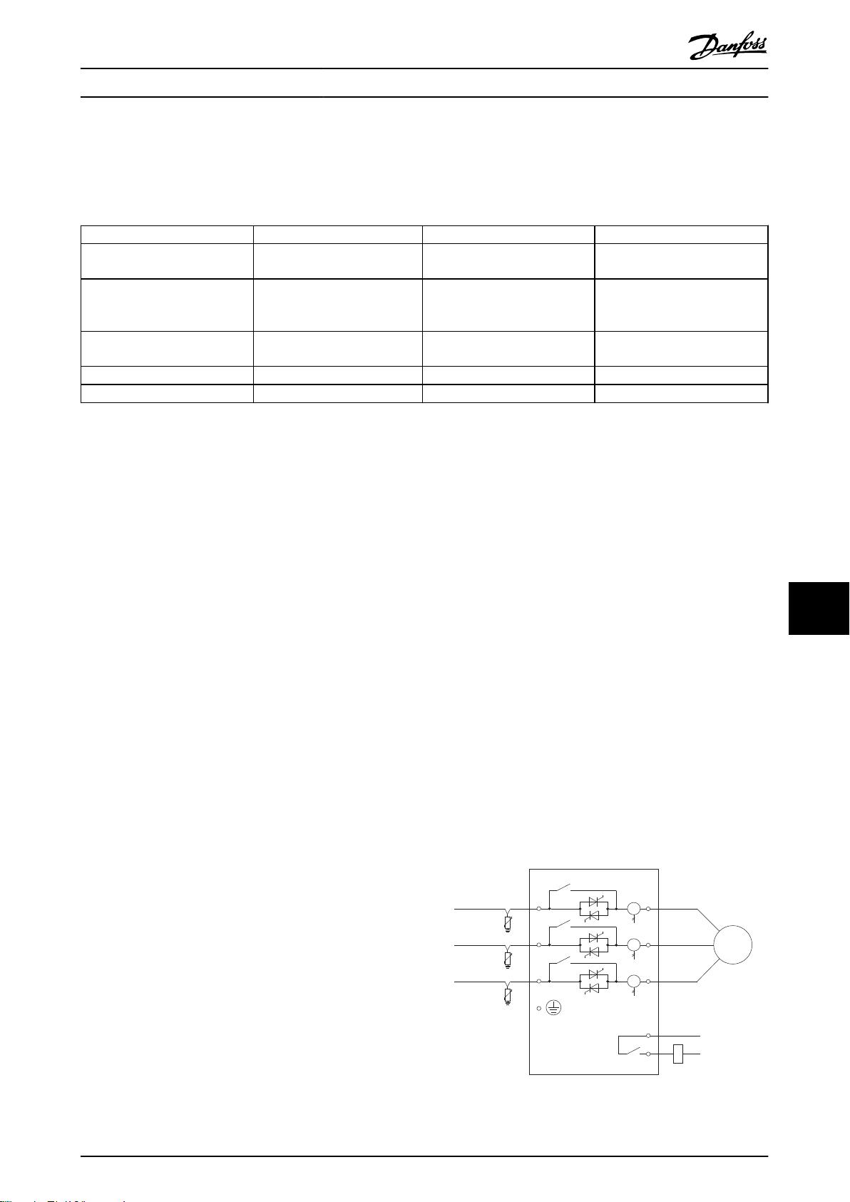
M
3
~
1/L1
2/T1
1/L1
1/L1
2/T1
2/T1
E
13
14
KM1
177RA001.10
Specifications MCD 500 Operating Instruction
10.1.3 PC Software
MCD PC Software can be used in conjunction with a communications module to provide the following functionality for
networks of up to 99 soft starters.
Feature MCD-201 MCD-202 MCD500
Operational control (Start, Stop,
Reset, Quick Stop)
Starter status monitoring (Ready,
Starting, Running, Stopping,
Tripped)
Performance monitoring (motor
current, motor temperature)
Upload parameter settings
Download parameter settings
Table 10.1
The PC software available from Danfoss's website is:
WinMaster: VLT® Soft Starter software for control, configuration and management
•
: VLT® software for configuration and management.
•
● ● ●
● ● ●
● ●
●
●
10.1.4
Finger guards may be specified for personnel safety and can be used on MCD 500 soft starter models 0131B - 1600C. Finger
guards fit over the soft starter terminals to prevent accidental contact with live terminals. Finger guards provide IP20
protection.
Finger Guard Kit
MCD5-0131B ~MCD5-0215B: 175G5662
•
MCD5-245C: 175G5663
•
MCD5-0360C ~MCD5-0927C: 175G5664
•
MCD5-1200C ~MCD5-1600C: 175G5665
•
10.1.5 Surge Protection Kit (Lightning Protection)
As standard, MCD 500 rated impulse withstand voltage is limited to 4 kV. The surge protection kits protect the system and
make the soft starter immune to high voltage impulses.
6kV
175G0100 SPD Surge protection kit for G1
•
175G0101 SPD Surge protection kit, G2-G5
•
12kV
10
10
175G0102 SPD Surge protection kit for G1
•
175G0103 SPD Surge protection kit, G1-G5
•
Illustration 10.1
MG17K402 - VLT® is a registered Danfoss trademark 77
Page 79

Bus Bar Adjustment Procedur... MCD 500 Operating Instruction
11 Bus Bar Adjustment Procedure (MCD5-0360C - MCD5-1600C)
NOTE
Many electronic components are sensitive to static electricity. Voltages so low that they cannot be felt, seen or heard, can
reduce the life, affect performance, or completely destroy sensitive electronic components. When performing service, proper
ESD equipment should be used to prevent possible damage from occurring.
All units are manufactured with input and output bus bars at the bottom of the unit as standard. The input and/or output
bus bars can be moved tot he top of the unit if required.
11
78 MG17K402 - VLT® is a registered Danfoss trademark
Page 80
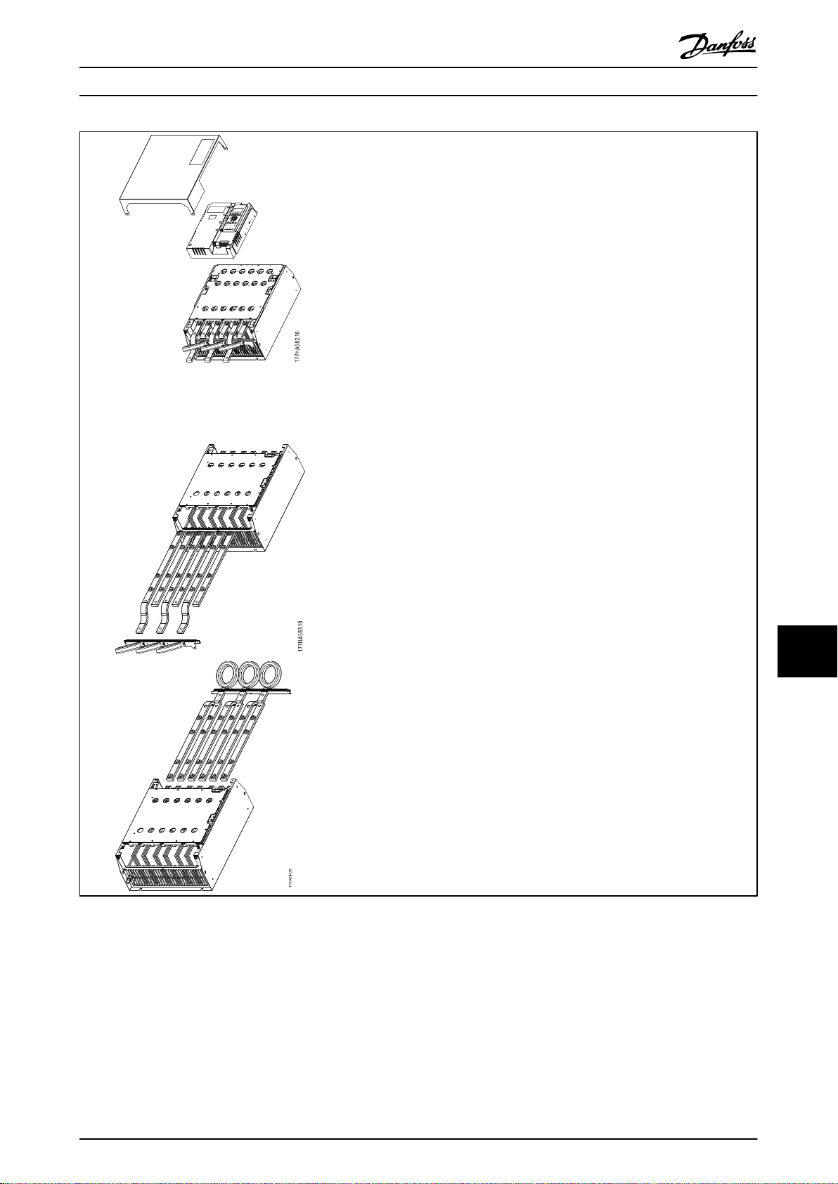
Bus Bar Adjustment Procedur... MCD 500 Operating Instruction
1. Remove all wiring and links from the soft starter before dismantling the unit.
2. Remove the unit cover (4 screws).
3. Unscrew the main plastic and fold away from the starter (4 screws).
4. Unplug the keypad loom from CON 1 (see note).
5. label each SCR firing loom with the number of the corresponding terminal on
the main control PCB, then unplug the looms.
6. Unplug the thermistor, fan and CT wires from the main control PCB.
NOTE
Remove the main plastic slowly to avoid damaging the keypad wiring loom which runs between the main plastic and the
backplane PCB.
1. Unscrew and remove the magnetic bypass plates (models MCD5-0620C to
MCD5-1600c ONLY).
2. Remove the CT assembly (three screws).
3. Identify which bus bars are to be moved. Remove the bolts holding these bus
bars in place then slide the bus bars out through the bottom of the starter
(four bolts per bus bar).
1. Slide the bus bars in through the top of the starter. For input bus bars, the
short curved end should be outside the starter. For output bus bars, the
unthreaded hole should be outside the starter.
2. Replace the dome washers with the flat face towards the bus bar, then
tighten the bolts holding the bus bars in place to 20 Nm.
3. Place the CT assembly over the input bus bars and screw the assembly to the
body of the starter (see note).
4. Run all wiring to the side of the starter and secure with cable ties.
Table 11.1
NOTE
If moving the input bars, the CTs must also be reconfigured.
1. Label the CTs L1, L2 and L3 (L1 is leftmost when working from the front of the starter). Remove the cable ties and
unscrew the CTs from the bracket.
2. Move the CT bracket to the top of the starter. Position the CTs for the correct phases, then screw the CTs to the
bracket. For models MCD5-0360C - MCD5-0930, the CTs must be placed on an angle (the left hand legs of each CT
will be on the top row of holes and the right hand legs will be on the bottom tabs).
11
11
MG17K402 - VLT® is a registered Danfoss trademark 79
Page 81
www.danfoss.com/drives
175R0549 MG17K402 Rev. 2012–03–05
*MG17K402*
 Loading...