

Vlinx ESR411W Quick Start Manual
p
A
p
Quick
Start
Guide
Vlinx
Wireless
Serial Server
Vlinx ESR411W
1. Package Checklist
The Vlinx Wireless Serial Server package
includes:
9 The Server unit
9 Quick Start Guide
9 CD-ROM Disk (Documentation and Software)
9 Footpads set
9 DIN Rail Kit
Not included:
9 Power Supply
9 Ethernet cables
9 Serial cables
9 Mounting screws
9 Power surge protection
9 Serial o
2. Both Ethernet and WLAN
1. Only one interface (Ethernet or WLAN) is
active at a time. The WLAN is active when
the Ethernet cable is disconnected. To
switch between Ethernet and WLAN, connect
or disconnect the Ethernet cable to a live
network or device, then press reset or cycle
International HQ: 815-433-5100 www.bb-elec.com
European HQ: +353 91 792444 www.bb-europe.com
Documentation Number Vlinx ESR41xW-2909qsg
tical isolation
ower.
2. If Ethernet is active, DHCP is enabled and can’t get
an IP address from the DHCP Server, the interface will
be assigned to 192.168.10.1. If WLAN is active
instead, interface will be assigned to 192.168.10.2
3. LED’s
LED Indication
PWR
RDY
CONS
WLAN
Signal Bars
P(Port) 1-4
LEDs on RJ45
connector
Red/Steady-Power applied
Green /Blinks-system ready
Green/Steady-Port1 Console mode
Green/Steady-WLAN active
Green/Rises with signal strength
Green/Off: Closed, ON: Active,
Blinks: Data traffic
Orange -- 10BaseT connection
Green -- 100BaseT connection
ON: No data Blinks: Data flow
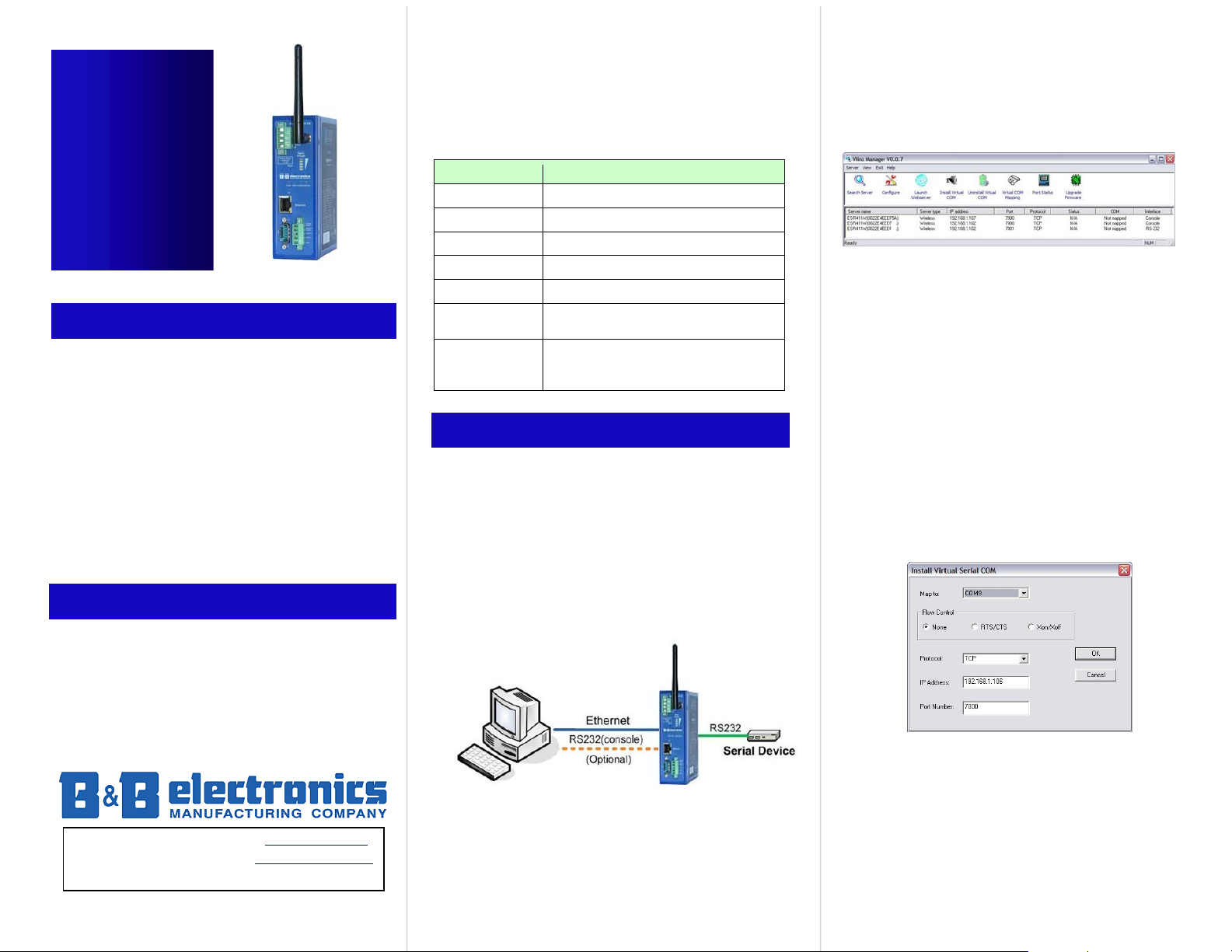
3. Ethernet (Wired) Set Up
5. Open the Vlinx Manager software. It will
automatically search for reachable Vlinx Serial
Server devices. A list of all Serial Servers
connected to the LAN will appear in the Vlinx
Serial Server List window.
6. Double clicking the selected Server on the Server
list will bring up web page. Use root as both
Username and Password to access web page.
7. Note: If Server(s) are not found, then host
computer and Server may not be on the same
subnet. Reconfigure host computer subnet to
match Server. Default subnet at start is
192.168.0.x as listed on Server side panel (x is
anything other than 1), subnet mask is
255.255.255.0
B: Install Virtual COM Driver (VCOM Mode):
: Installation and Setup, Socket Mode (Default
Mode):
1. Install the Vlinx Manager software on the host system.
2. Connect the Server to the Host PC with a crossover
Ethernet cable.
3. Connect the Server serial port to the serial device. For
DCE, use a straight through cable. For DTE, use a
crossover (null modem cable)
4. Reboot the Server by pressing Reset or cycle power.
After startup (about 35 seconds) the RDY LED will
start blinking.
1. Open the Vlinx Manager software. Highlight the
Server in the server list found by the Vlinx
Manager.
2. Click on the Install Virtual COM icon from the
menu. The following window opens:
3. Select an unused COM port (best practice is
COM5 and up) to map to the IP address and Port
(default is Port 7000). Select desired Flow Control
and protocol (TCP/UDP)
C: Test Data Communications:
1. Run the terminal emulation program (such as
PuTTY). Select COM port (e.g. Port 5 or above).
[continued back page]
A
[continued from Test Communications, first page]
2. Set Serial Type, Baud Rate, Data/Parity/Stop,
and Flow Control to match the configuration of
the serial device connected to the Server serial
port.
3. Enter Console mode from Vlinx™ web server.
4. Press space bar, check Properties page to
validate the Server is working.
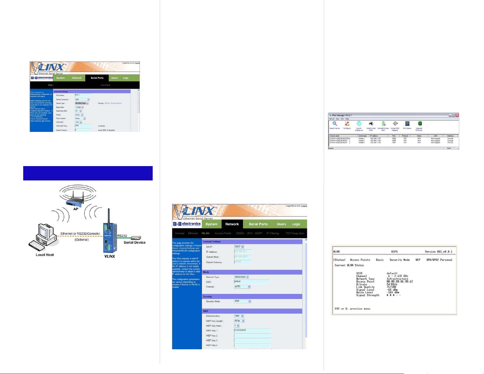
4. WLAN (Wireless) Set Up
4. Reboot the Server (push Reset button cycle power).
After startup the RDY LED starts blinking .
5. Set up the wireless network configuration for your
Host PC connection to AP (wireless Access Point).
6. Set up the wireless network configuration for your
Serial Server connection to AP.
Configure the WLAN settings via Ethernet port --a. Connect the Server to a Host PC via a crossover
Ethernet cable.
b. Reboot the Server (push Reset button or cycle
power).
c. Log in the Server through Launch Webserver icon
Configure the WLAN settings via Serial Console
(use Serial Port 1).
a. Run a terminal emulation program (such as
HyperTerminal or PuTTY) with the following settings:
115200, 8-N-1.
b. Configure the WLAN settings to match your AP’s
settings (Network Type, SSID, Security Mode, Key,
etc). A typical setting example is illustrated as below:
7. Set up the wireless network configuration for your
Server connection to match the AP configuration:
Note 1: Please make sure Host PC and Serial
Server are in the same subnet. For wider access
set DHCP to Enable at “Network Settings” on web
page.
Note 2: After configuration, disconnect the
Ethernet (or serial) cable and reboot the Serial
Server.
8. Open the Vlinx Manager software. It will
automatically search for reachable Server s. A list
of all Servers connected to the LAN will appear in
the Server List window.
9. Double clicking the selected Server on the server
list will bring up the web page.
Note: If you cannot see Server appearing on the
search server list, correct the wireless network
settings to enable the WLAN network connection.
You can check out the WLAN settings using the
Ethernet port or through Serial port 1 at Console
mode.
: Installation and Setup, Socket Mode
(Default mode):
1. Install the Vlinx Manager software on the host
computer.
2. Connect the Server serial Port to the serial
device. For DCE, use a straight through cable.
For DTE, use a crossover (null modem cable)
3. Connect Ethernet cable or serial null modem
cable between host computer and Server (use
Serial Port 1 on Server for serial connection).
10. Confirm whether the WLAN settings match the
AP’s. For example, from the console UI, check out
the WLAN Status, like screen below.
B: Install Virtual COM Driver:
(Refer to section 2-B, first page)
C: Test Data Communications:
(Refer to section 2-C, first page)
 Loading...