


Version 07.04.2011
Video-inserter
VL2-MMI2G
for Audi with MMI2G navigation system
Video-inserter with 2 video + RGB + rear-view camera input

Version 07.04.2011 VL2-MMI2G
Page2
Contents
1. Prior to installation
1.1. Delivery contents
1.2. Checking the compatibility of vehicle and accessories
1.3. Dip-switch settings
1.3.1. Enabling the interface’s video inputs (dip 1-3)
1.3.2. Rear-view camera settings (dip 5)
2. Installation
2.1. Place of installation
2.2. Connections
2.3. Installation procedure – function check
2.4. Picture settings
2.5. Audio insertion
2.6. Connecting 2 AV sources
3. Interface operation
4. Specifications
5. Technical support
Legal Information
By law, watching moving pictures while driving is prohibited, the driver must not be
distracted. We do not accept any liability for material damage or personal injury resulting,
directly or indirectly, from installation or operation of this product. This product should only
be used while standing or to display fixed menus or rear-view-camera video when the
vehicle is moving, for example the MP3 menu for DVD upgrades.
Changes/updates of the vehicle’s software can cause malfunctions of the interface. We
offer free software-updates for our interfaces for one year after purchase. To receive a free
update, the interface must be sent in at own cost. Labor cost for and other expenses
involved with the software-updates will not be refunded.

Version 07.04.2011 VL2-MMI2G
Page3
Product features
RGB-input for after-market navigation
2 video-inputs for after-market devices (e.g. DVD-Player, DVB-T tuner, …)
Built-in audio-switch
Rear-view camera input, automatically switching
Factory rear-view camera compatible
PAL/NTSC input compatible
Wrong-plugging circuit protection
1. Prior to installation
Read the manual prior to installation.
Technical knowledge is necessary for installation. The place of installation must be free of
moisture and away from heat sources.
1.1. Delivery contents
Take down the serial number of the interface and store this manual for support
purposes: ____________________

Version 07.04.2011 VL2-MMI2G
Page4
Requirements
General monitor with 4pin LVDS Mitsumi connector on backside
Vehicle Audi A4, A5 (B8), A6 (4F), A8 (4D/4E), Q7 (4L)
Navigation/Radio Navigation MMI 2. generation
Limitations
Video only The interface inserts ONLY video into the infotainment,
for sound use the FM-modulator or an AUX-in interface
AUX-1xx or a Dension Gateway 500.
1.2. Checking the compatibility of vehicle and accessories
1.3. Dip-switch settings
With the video interface boxes dip-switches it is possible to dis- or enable the interfaces
inputs (dip 1 to 3) and to preselect the type of camera which is (to be)
installed (dip 5).
Dip position down is ON and position up is OFF.
1.3.1. Enabling the interface’s video inputs (dip 1-3)
Only the enabled video inputs can be accessed when switching through the video sources. It
is recommended to enable only the required inputs.
Dip
Video-input
ON (down)
OFF (up)
Dip 1
RGB
enabled
disabled
Dip 2
Video IN1
enabled
disabled
Dip 3
Video IN2
enabled
disabled

Version 07.04.2011 VL2-MMI2G
Page5
1.3.2. Rear-view camera settings (dip 5)
Depending on whether no camera, after-market camera or factory camera shall be used, dip
5 must use different settings.
If set to OFF, the interface switches to factory LVDS picture
when the reverse gear is engaged to display factory rear-view
camera or factory PDC picture. The green wire of the video-
interface’s 6pin power connector must be connected to reverse
light (+12V of reverse light signal) by using a relay, ONLY if
camera shall is (to be) installed.
2. Installation
Switch off ignition and disconnect the vehicle’s battery! The interface needs a
permanent 12V source. If according to factory rules disconnecting the battery
is to be avoided, it is usually sufficient to put the vehicle is sleep-mode. In
case the sleep-mode does not show success, disconnect the battery with a
resistor lead.
If power source is not taken directly from the battery, the connection has to be
checked for being start-up proven and permanent.
2.1. Place of installation
The Interface has to be installed into the LVDS leads between monitor control-box and
monitor. The monitor control box is located at A6, A8 and Q7 behind the dash board, at A4
and A5 behind the air-conditioning control panel.
Rear-view
camera type
Dip 5
None
OFF
Factory
OFF
After-market
ON
Version 07.04.2011 VL2-MMI2G
Page6
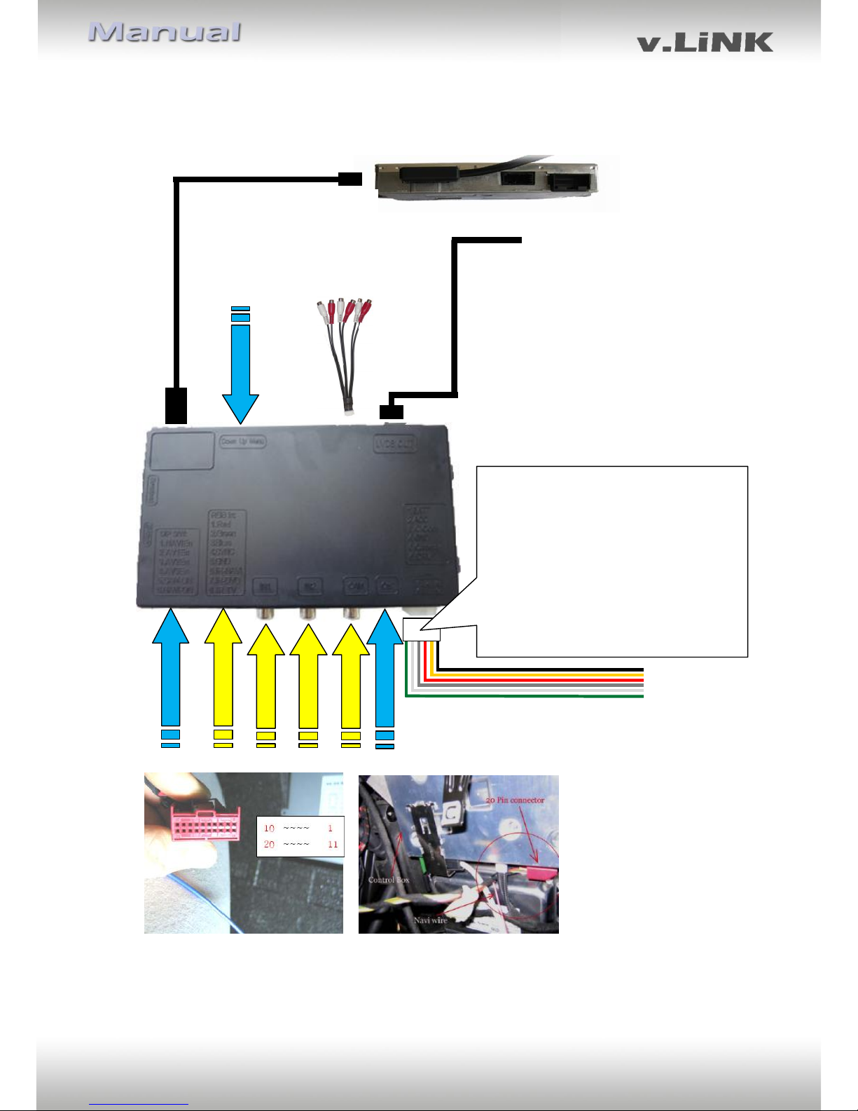
2.2. Connections
Video interface
Mitsumi
interface LVDS
cable
Backside monitor control-box
LVDS lead of
factory harness
DIP Switches
RGB Input
Video-IN1
Video-IN2
Camera-IN
Pic settings
Pin-definition white 6pin power connector
Pin 1 (yellow) - ACC or BAT +12V
Pin 2 (red) - ACC +12V
Pin 3 (grey) - No function
Pin 4 (black) - Ground
Pin 5 (green) - Rear-view camera input
switch to CAM on
+12V signal
Pin 6 (white) - iDrv-signal (connect to pin
16 of the 20pin connector or
+12V through pushbutton
CTRL-port
6pin power cable
The vehicles MMI wire is on pin 16 of the 20pin connector of the monitor
control-box. The connector can be red or black.
No liability for vehicle wire colors and pin definition!
Possible changes by the vehicle manufacturer. The given
information must be verified by the installer.
Female Mitsumi
interface LVDS
connector
female Mitsumi LVDS
connector of factory
harness
AudioKabel

Version 07.04.2011 VL2-MMI2G
Page7
2.3. Installation procedure – function check
Follow the below procedure using the “Connections” scheme from chapter 2.2. as reference.
Before the installation of the sources and the interface we recommend a first quick
connection of the interface and test run to ensure that vehicle and product are compatible.
Due to changes in production of the vehicle manufacturer there is always the possibility of
incompatibility.
- Switch off ignition and disconnect vehicle’s battery
- Disconnect the factory harness’ femaleMitsumi LVDS connector from monitor
control- box and connect it to male LVDS Mitsumi connector of video interface
- Connect female Mitsumi interface LVDS connector male Mitsumi LVDS connector of
monitor control-box
- Connect 6pin power cable to video interface and to power as described in chapter
2.2.
- Connect white wire of 6pin power cable (iDrv) to pin 16 of the 20pin connector from
the monitor control box (alternatively by external switch +12V, see chapter 3.)
- If 2 audio sources shall be used, connect it according to chapter 2.6.
- Connect Mitsumi interface LVDS cable to LVDS IN of video interface
- Reconnect battery and turn on ignition
- Check LEDs on CAN box and video interface, one on each must be on
- Try to activate video sources by infotainment buttons and by external switch (see
chapter 3.), using a test picture source
- If camera is (to be) connected connect green wire of 6pin power cable to +12V to see
whether the automatic switching to camera input works. Later connect green wire to
reverse gear light, using a relay
- If 2 audio sources shall be used, connect the audio wires and check the audio
function
- ONLY after positive function check proceed with installation of the video sources!
- After installation and connection of the real video source(s), adjust picture settings
(see chapter 2.4.)
Note: If the interface is used in combination with the AUX-in interfaces AUX-1xx, the white
iDrv wire can alternatively be connected to the orange activation wire of the AUX-in
interface. Then the AV-inputs will be controlled by the AUX-in interface (see manual of the
AUX-1xx).
Important! Do not connect the white wire additionally to pin 16 of the monitor control box
when connected to the AUX-in interface.

Version 07.04.2011 VL2-MMI2G
Page8
2.4. Picture settings
After installing the sources the picture settings can be changed using a pen on the buttons of
the video interface. Press the MENU button to open settings menu on the OSD and to switch
to the next setting. UP and DOWN change the corresponding values. The buttons are
embedded in the housing to avoid accidental changes during or after installation.
2.5. Audio insertion
This interface can only insert video into the factory infotainment. The video can be activated
to any audio mode of the factory infotainment. If an AV-source is to be connected, the
source’s video out is connected to the video IN1 of the video interface and the source’s
audio out to the audio insertion. Audio insertion is possible by AUX in interfaces AUX-1xx or
Dension Gateway 500 or FM-modulator.
2.6. Connecting 2 AV-sources
If two AV-sources shall be connected, connect the included audio cable to audio-switch-port
of the video interface. When switching the video interface from video-IN1 to video-IN2, the
audio will also automatically be switched.
Audio pins
Definition
1/2
Audio input signal R/L of source IN2
3/4
Audio input signal R/L of source IN1
5/6
Audio output signal R/L of AUX-1xx, Gateway
500 or FM-modulator
7
Ground
8
No function
Audio-cable
Video-interface
Audio-switch-port

Version 07.04.2011 VL2-MMI2G
Page9
3. Interface operation
The NAV button is used to execute interface functions.
Press NAV button – video input switching,
Each press will switch to the next enabled input. If all inputs are enabled the order is:
Factory video RGB-in video IN1 video IN2 factory video …
Inputs which are not enabled are skipped. If the audio cable is connected, when switching
from video IN1 to video IN2, also the sound will be switched.
4. Specifications
BATT/ACC range 7V ~ 25V
Power 0.3A @12V
Video input 0.7V~1V
Video input formats PAL/NTSC
Weight 195g
Dimensions (box only) B x H x T 182 x 24 x 100 mm
5. Technical Support
NavLinkz GmbH Caraudio-Systems Vertriebs GmbH
distribution/tech dealer-support distribution
Eurotec-Ring 45 Rheinhorststr. 22
D-47445 Moers D-67071 Ludwigshafen am Rhein
phone +49 2841 949970
email mail@navlinkz.de
 Loading...