

Page 1
YODA
Recommendations for assembly
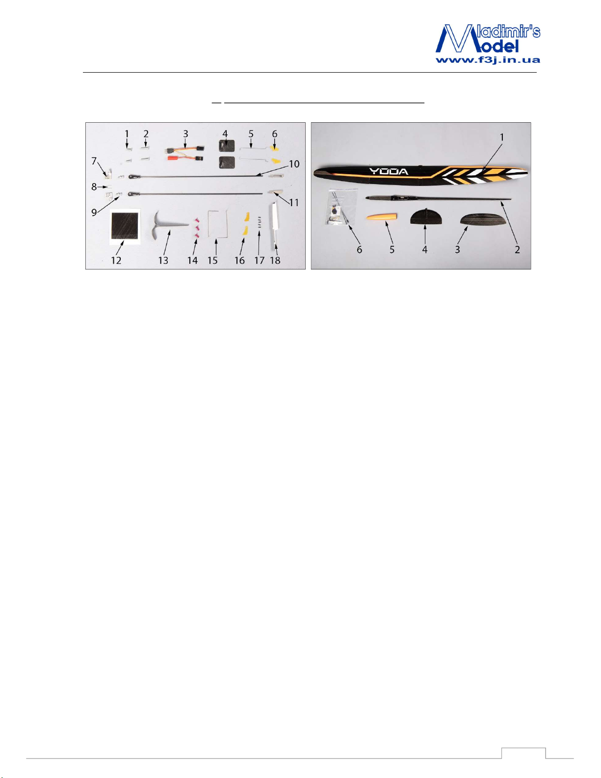
1. The list of parts and materials to build:
Accessory kit: Parts set:
1. Rear short screws for fixing wing (M3x10 , 1 spare
screw);
2. Forward long screws for fixing wing (M3x14, 1 spare
screw);
3. Fuselage part of the wire for aileron servos with JST
battery connector;
4. Yoda aileron servo hatches (left and right);
5. Yoda aileron rods (2pcs);
6. Yoda aileron horns (2 pcs);
7. Yoda aluminum flap horns (Snipe 2 aileron horns) (left
and right);
8. Aileron horn pins (D1x10, 2 pcs);
9. Yoda (Snipe 2) Ball link skrews; (2 pcs);
10. Yoda aileron rods (2 pcs);
11. Aileron clevises (with M2.5 thread);
12. Carboline SC 78 4/30 carbon for fixing aileron pins(1 pcs;
50x50 mm);
13. Yoda (Snipe 2) wing throwing peg;
14. Stabilizer fixing screws (M3x8, Aluminum, 1 pc spare);
15. Elevator and rudder torsion springs;
16. Elevator and rudder control horns;
17. Pipes for the fixing control cables (1 spare);
18. Yoda (Snipe 2) ballast fixing part;
1. Yoda wing;
2. Yoda fuselage;
3. Yoda (Snipe 2) horizontal stabilizer;
4. Yoda vertical stabilizer;
5. Yoda nose cone;
6. Yoda accessoires kit;
The list of materials needed to build the model:
1) Superglue and liquid medium, the accelerator
2) Cutter
3) Masking tape
4) Pen and ruler
5) Pliers
6) Sandpaper number 240-320
1
Page 2
YODA
Recommendations for assembly
2. Assembling the model
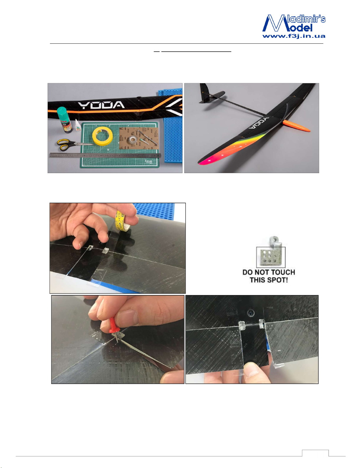
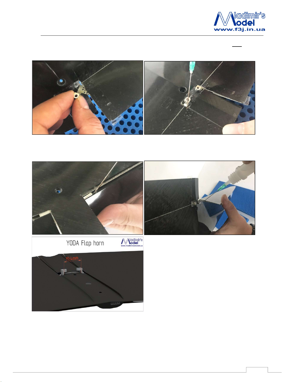
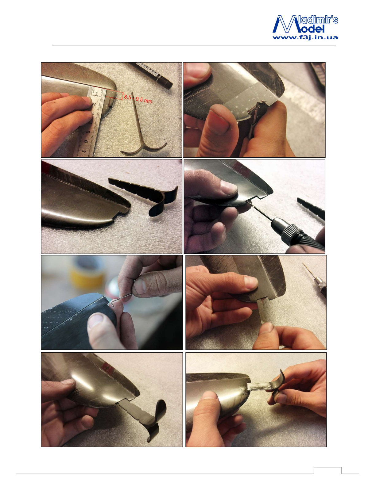
2.1 Flap horns installation.
This is very important sequence to follow for successful control installation.
Place a small piece of tape on bottom of flap over control horn and make small hole in flap with pin for
glue hole.
CAUTION!
Gluing zone of aluminium horn is covered with
primer for epoxy and CA!
2
Page 3
YODA
Recommendations for assembly
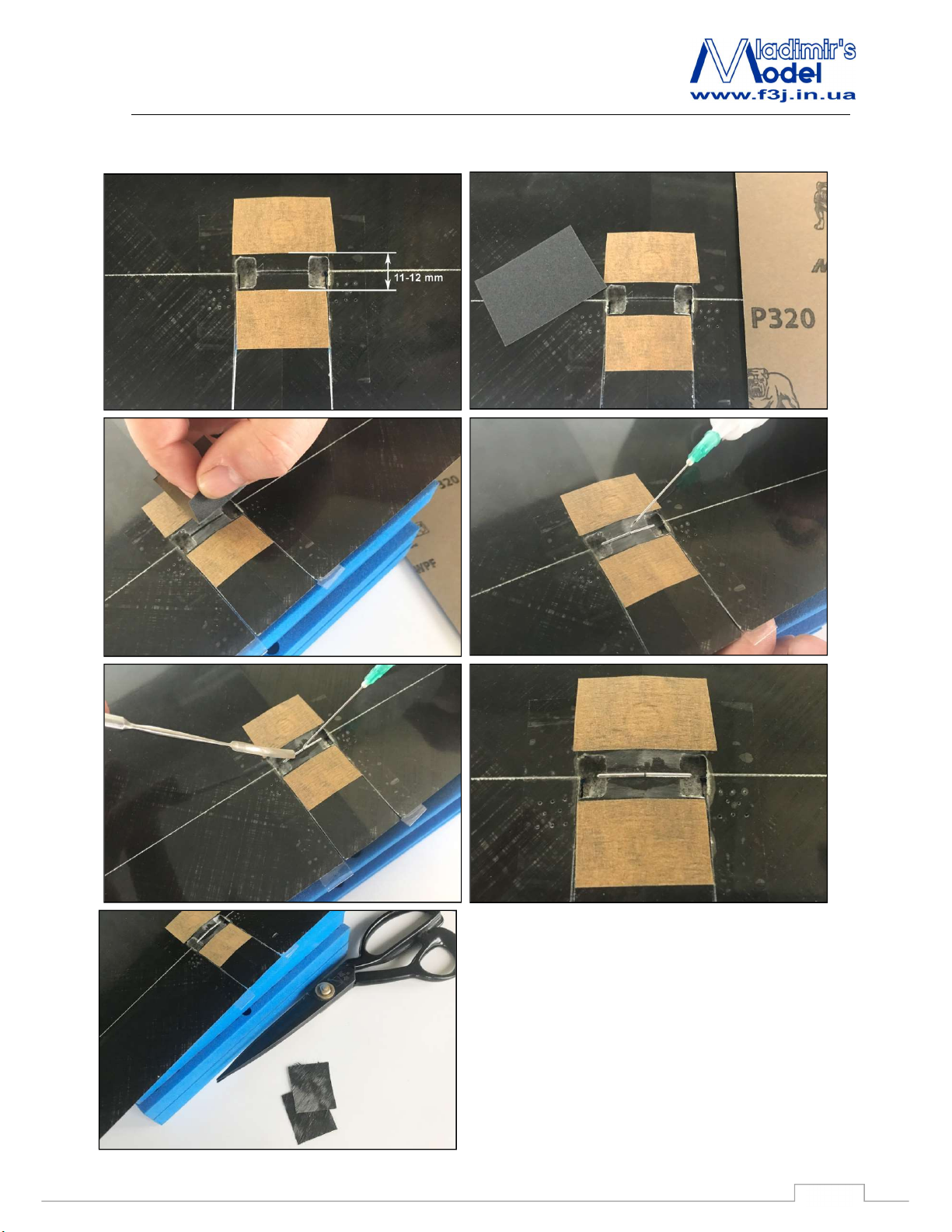
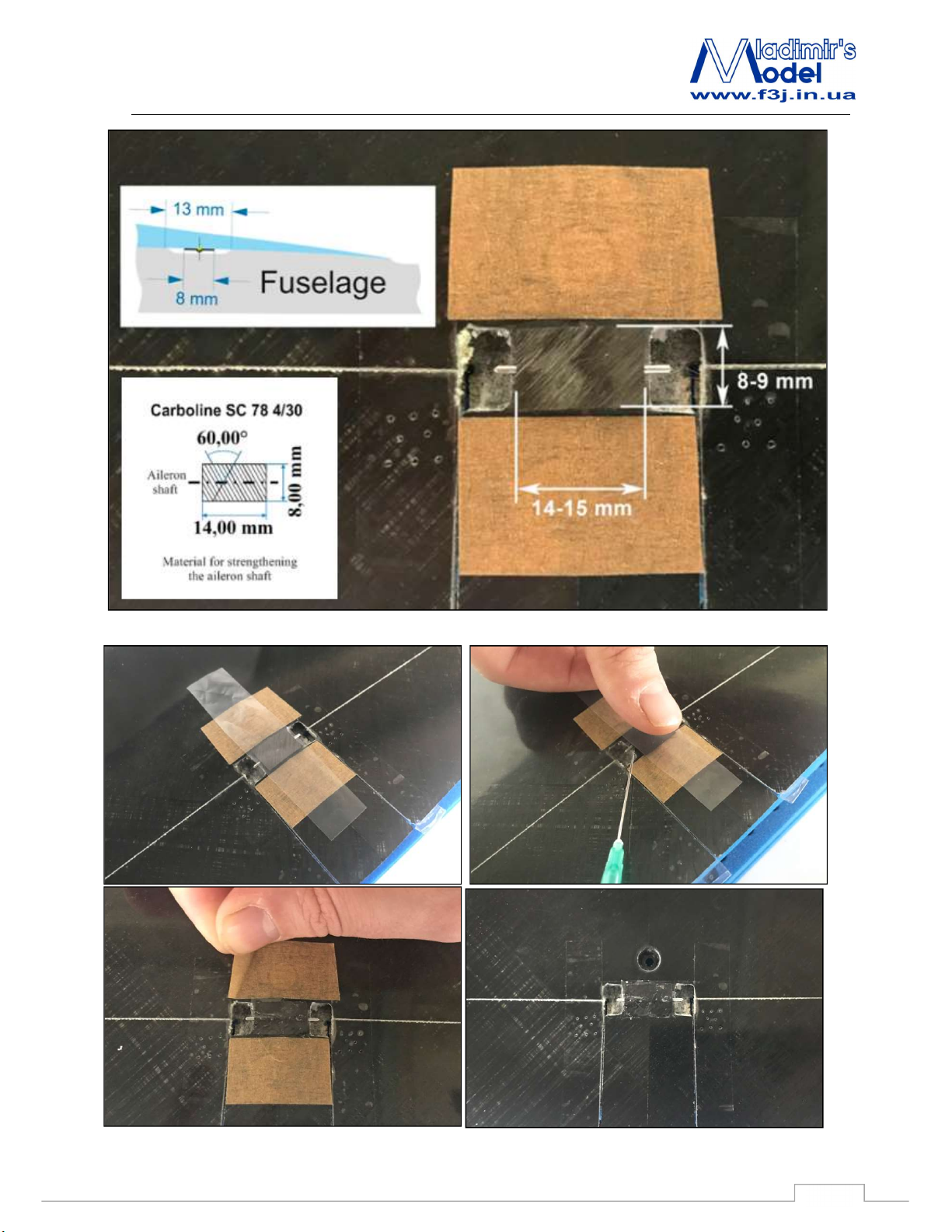
Glue pins in groves at bottom of wing.
Reinforce aileron’s pins by 2-3 layers of Carboline
SC 39 2/45 (8x14 mm).
3
Page 4
YODA
Recommendations for assembly
4
Page 5
YODA
Recommendations for assembly
Then slide control horn into slot in flap. Next, slide control horn on pin and push horn to inside edge of hole,
toward center of wing. Leave just enough clearance between horn and hole so the horn does not scrape edge of
hole.
Use some thin CA and drip glue into pin hole. When CA is dry, remove tape. Pull flap down and fill space
around control horn with CA.
5
Page 6
YODA
Recommendations for assembly
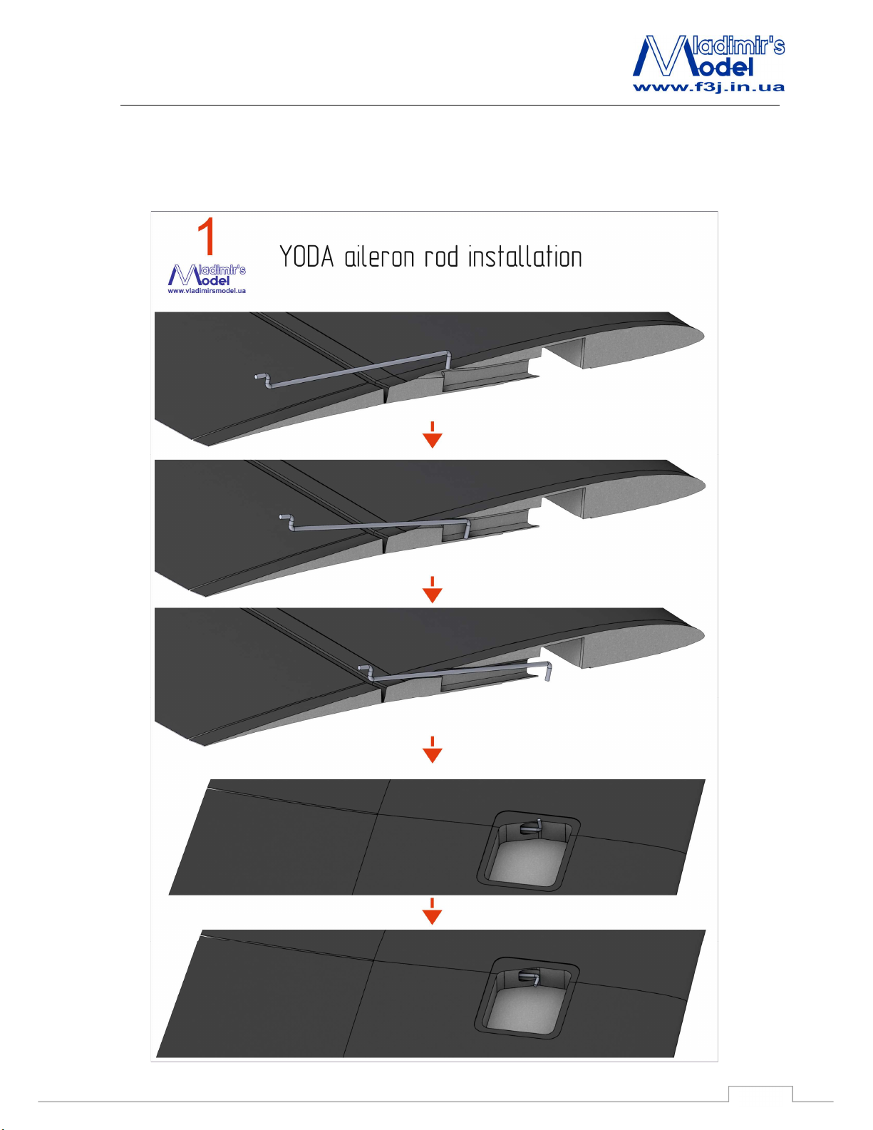
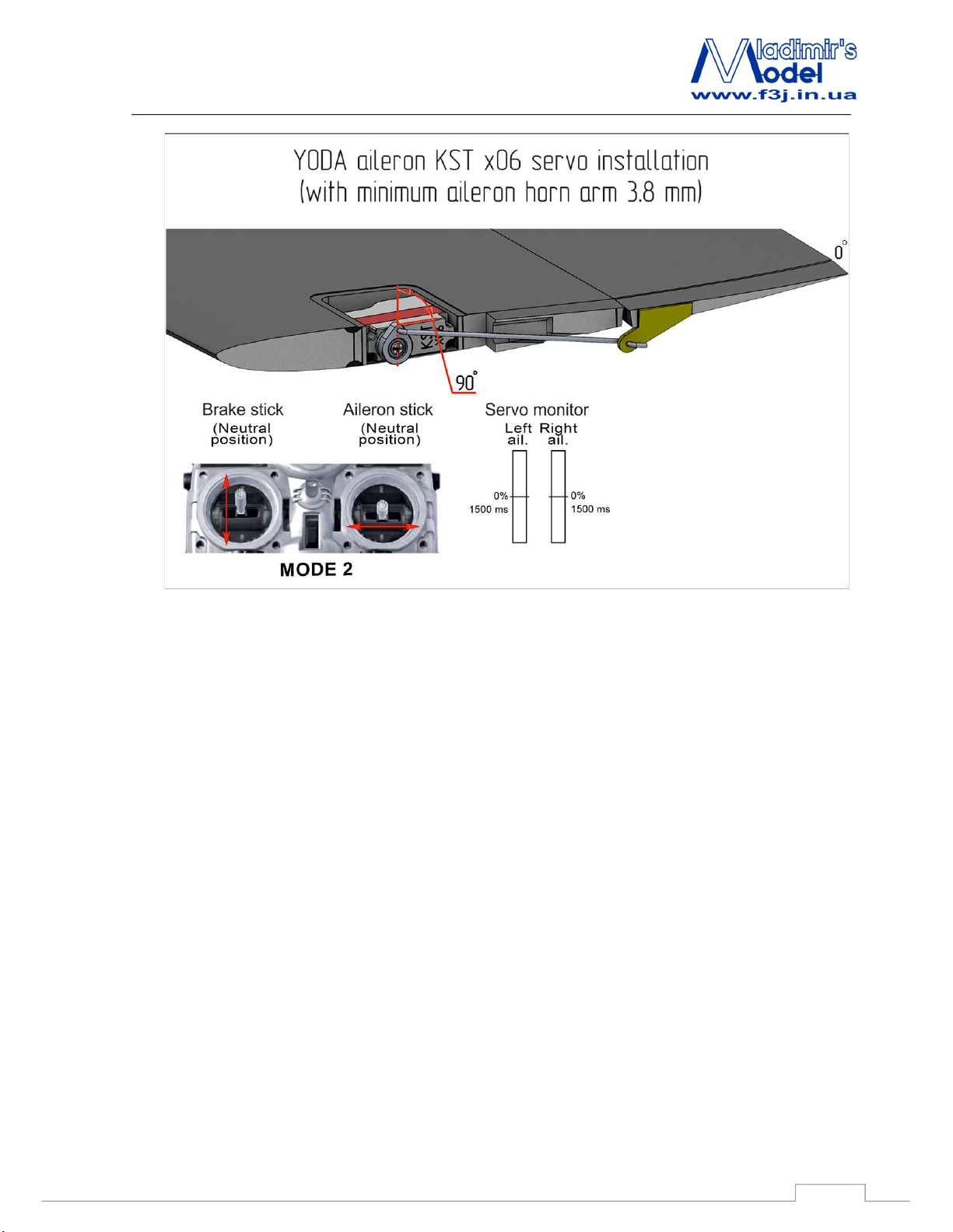
2.2 Yoda aileron servo and horn installation.
You must insert the rod from the outside of the wing and rotate it 90 degrees.
6
Page 7
YODA
Recommendations for assembly
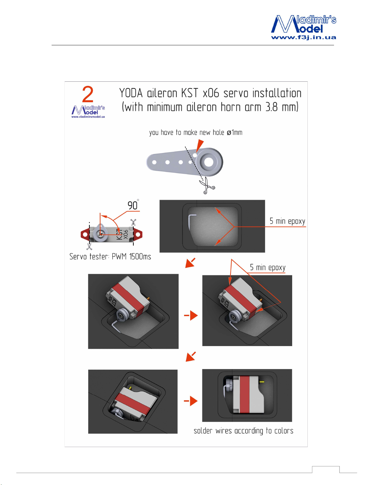
Drill a 1mm hole as close as possible to the base of the servo horn and cut the horn to the minimum size.
In the middle position of the servo, install the horn at an angle of 90 degrees to the servo.
Spread epoxy on the sides of the servos and the sides of servo spot.
Put the servo horn to the rod and insert the servo into the place.
It is necessary to fix the servo until the resin cures with thick super glue.
7
Page 8
YODA
Recommendations for assembly
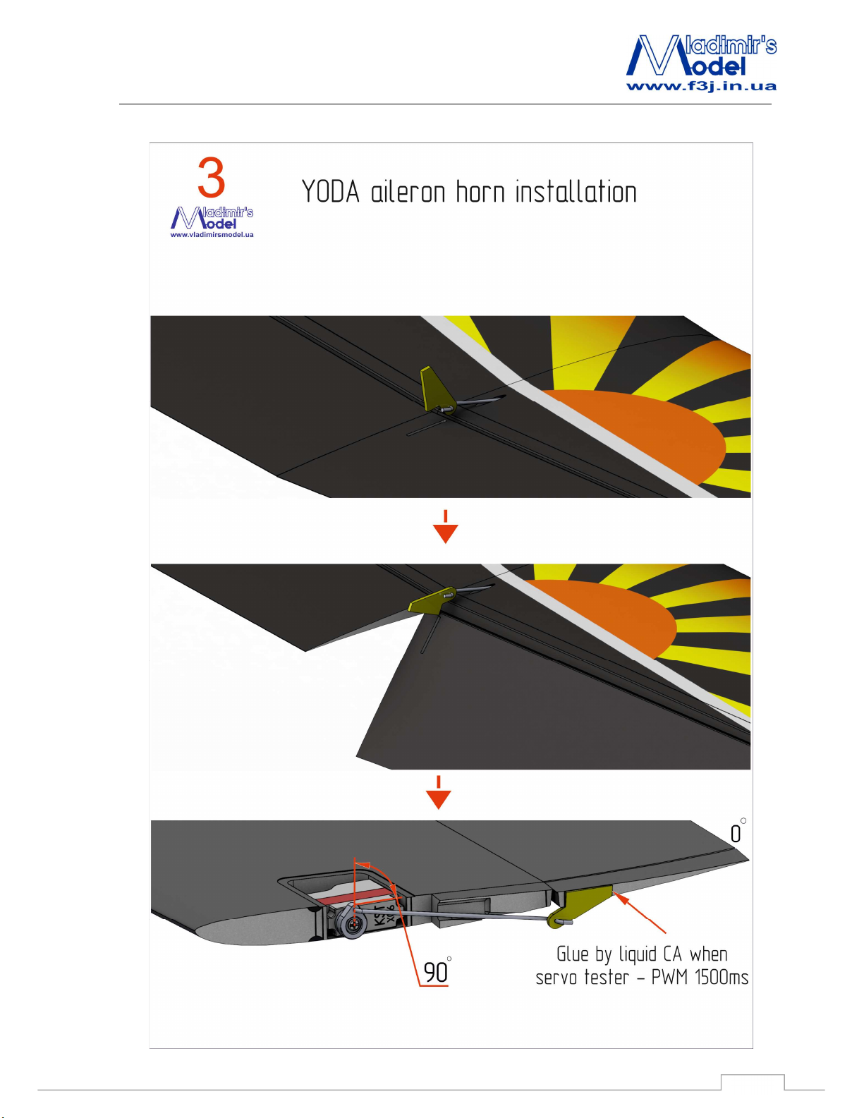
After resin polymerization, put on the aileron horn to the rod. Set the neutral position of the servo and
aileron and fix the horn in the aileron with thin superglue in this neutral position.
8
Page 9
YODA
Recommendations for assembly
9
Page 10
YODA
Recommendations for assembly
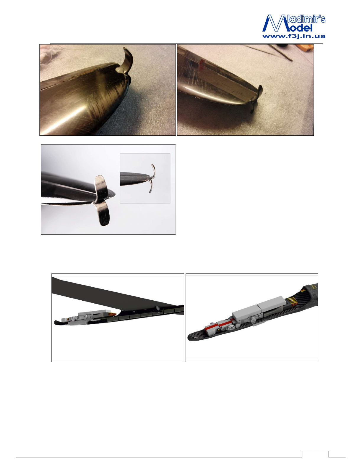
2.3 Launching peg installation.
10
Page 11
YODA
Recommendations for assembly
Please rewind the base of throwing peg by Kevlar thread
to avoid peg delamination, like fig.
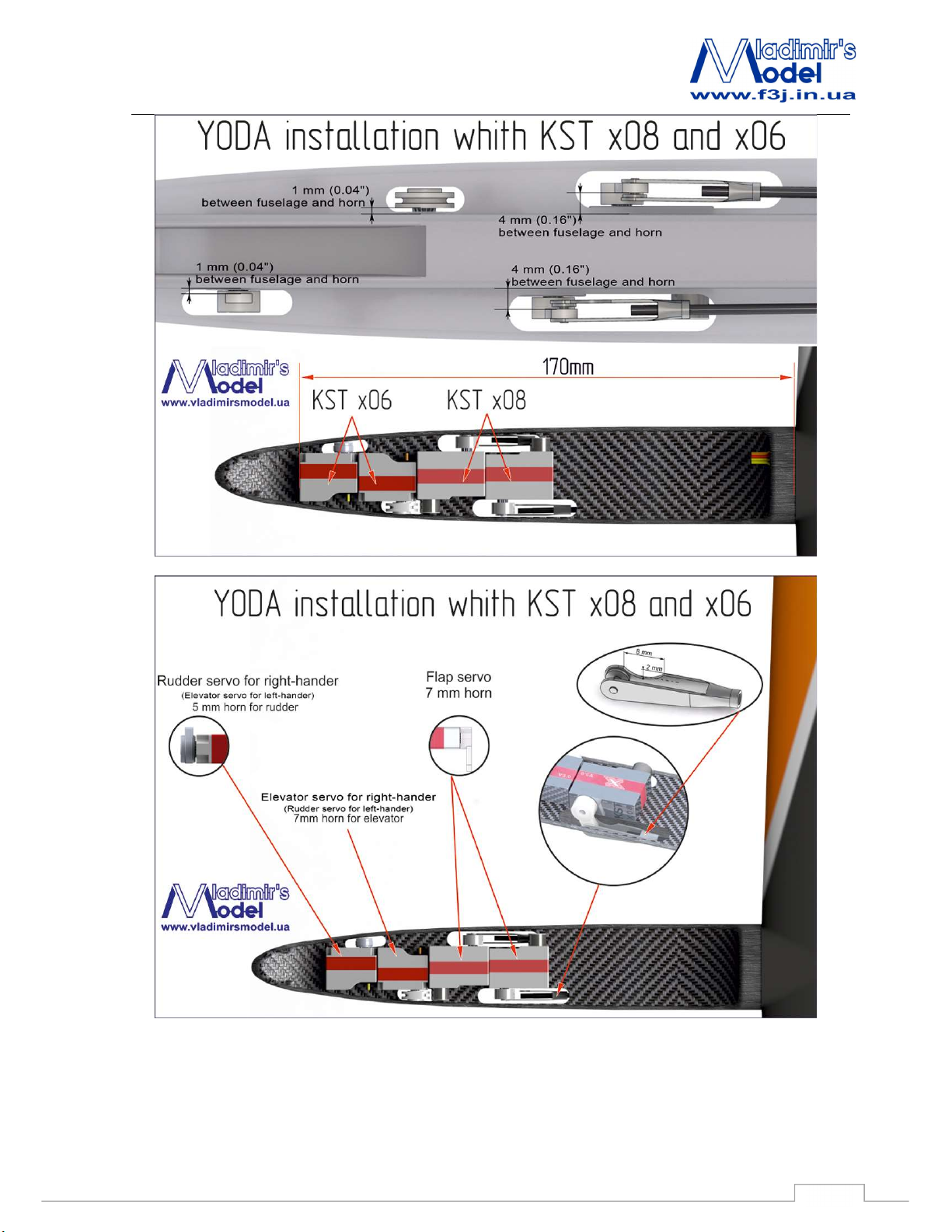
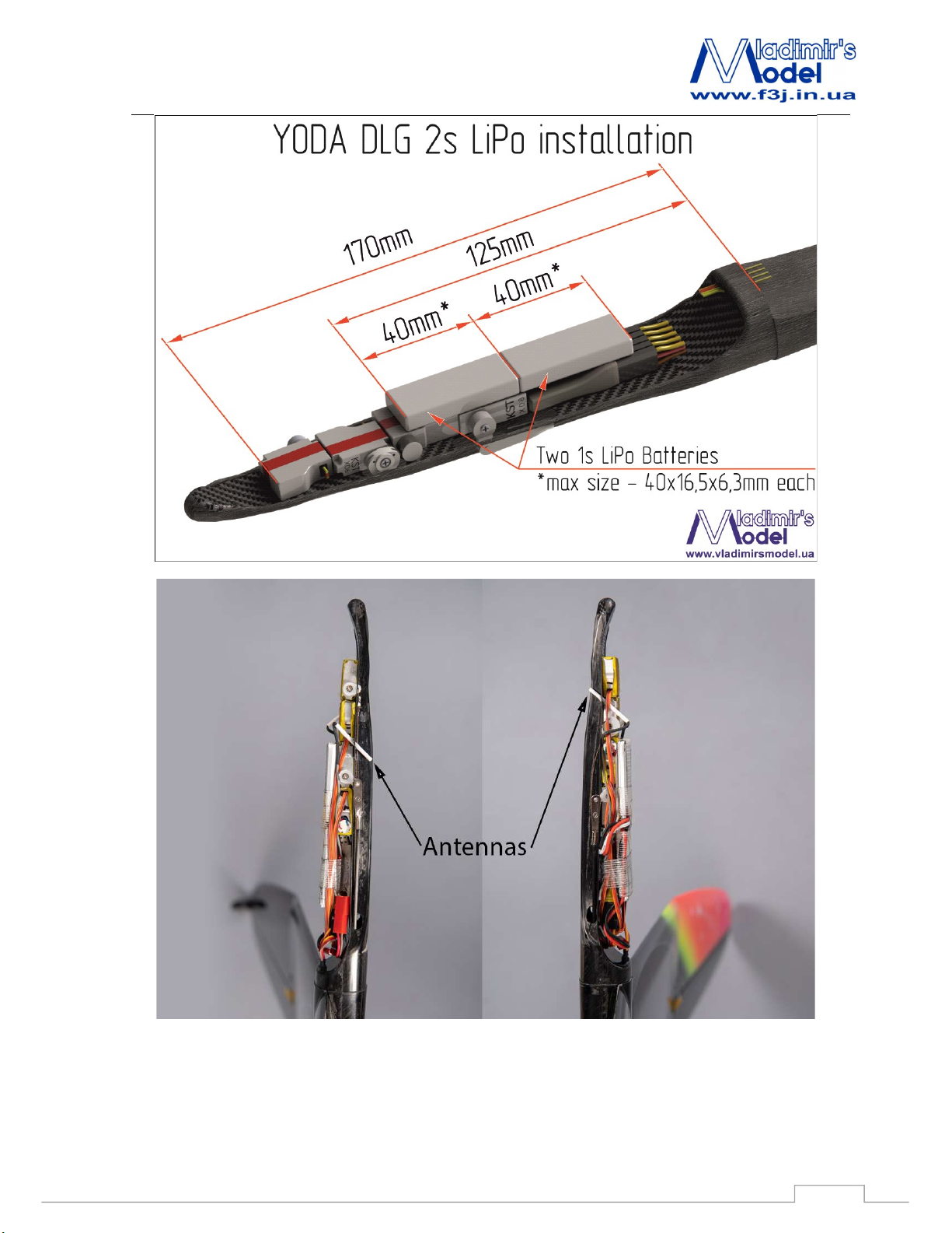
2.4 Fuselage servo accomodation.
11
Page 12
YODA
Recommendations for assembly
12
Page 13
YODA
Recommendations for assembly
13
Page 14
YODA
Recommendations for assembly
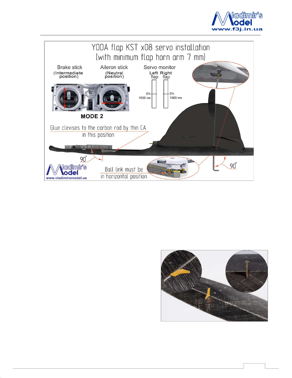
- The flaps have the same horns as in Snipe 2. ball head screws are screwed through the holes in the
fuselage with a 2.5 mm wrench. Use wrench without sphere.
- To screw the horn, you need to turn the flap down 18 degrees.
- We have to fix wing by two M3 screew: the longer screw for front and shorter to the back side.
2.5 Rudder and Elevator installation.
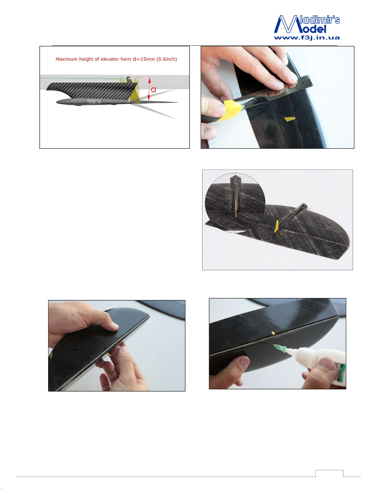
With a knife cut the slots in the elevator and rudder
in these locations. (Fig. 2.1 - 2.2).
Elevator horn is exactly in the center (along the
axis of the stabilizer mounting holes) as the position
must coincide with the slot in the pylon and tail boom.
Horns must be glued full depth to elevator.
Liquid superglue Glue Horns in elevator and
rudder..
Note:
- the maximum height of the elevator horn is 15
mm (Fig. 2.3)
Figure 2.1 - Bonding elevator horn
14
Page 15
YODA
Recommendations for assembly
Figure 2.3 - Maximum elevator horn length
Bonding of torsion spring in the control
surfaces
Center torsion spring on the control surface. (Fig. 2.4)
Figure 2.2 – rudder horn installation location
Make holes for the torsion spring with a needle and
install torsion spring with superglue. (Fig. 2.5, 2.6) Torsion
spring should provide force to the opposite side of the
control horn.
Figure 2.5 - Insert the torsion bar in the tail
Figure 2.4-Torsion spring location
Figure 2.6 - Sizing torsion feathers
15
Page 16
YODA
Recommendations for assembly
2.6 Yoda Fin installation.
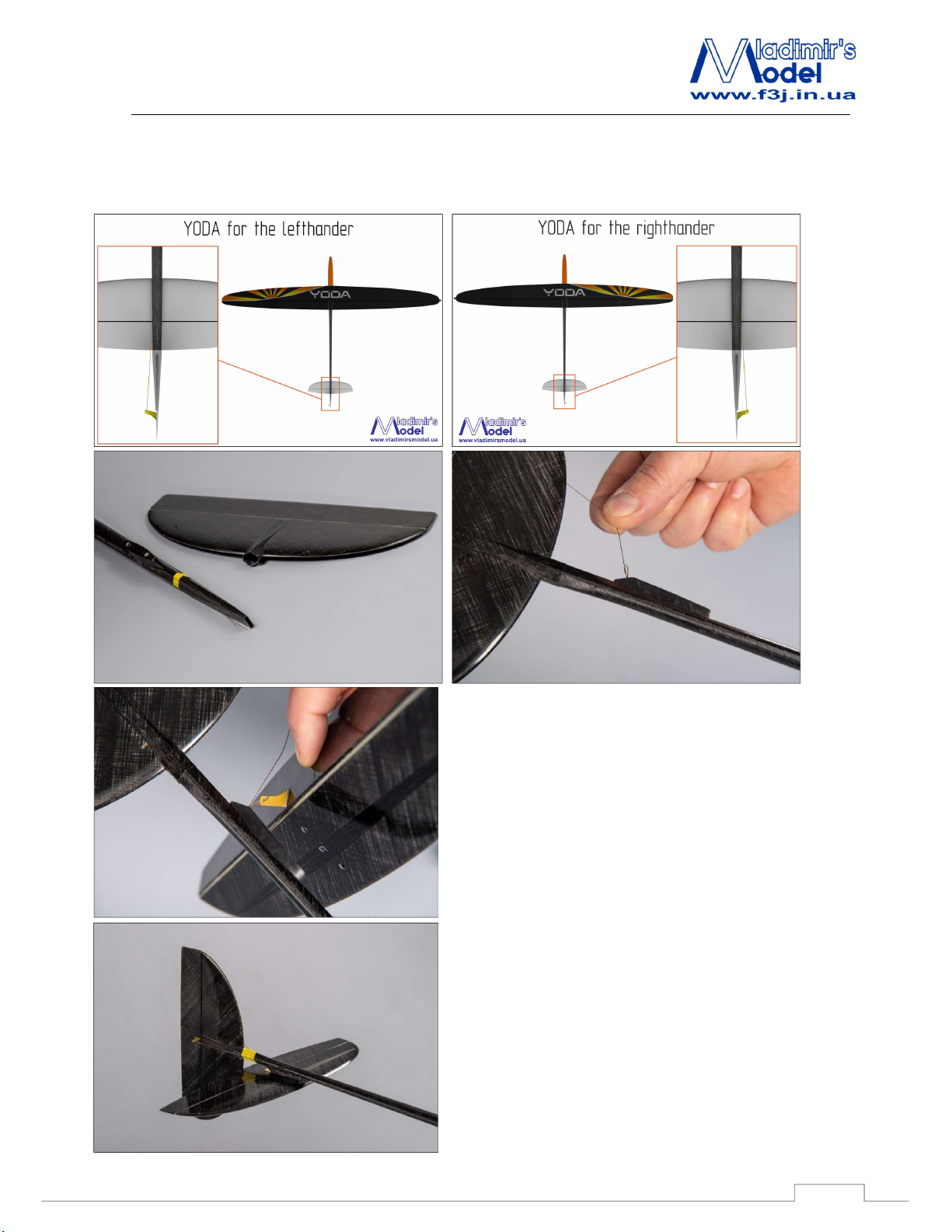
Yoda fin is removable now. It is the same for left and right hander because the Yoda fin is symmetrical.
Important: Put on Yoda fin to the fuselage until stop and fix it by tape before flight!
ATTENTION:
You must put on the fin to the fuselage until it stops
and fixed with tape.
Masking tape will do.
16
Page 17
YODA
Recommendations for assembly
2.7 Rudder and Elevator control cables.
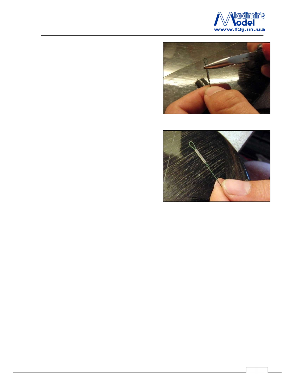
Insert the wire through the hole on the control horn.
Using a tube for cables (which you'll find in the
accessories kit) with a pair of pliers to crimp the cable
as photo 2.11
To make a draft of the stabilizer of a cable loop and
crimp its tube for fixing the rope. (Fig. 2.12).
For assistance in assembly, attach a 100 mm thread
to the elevator cable. You can lock the thread on the
tail boom with tape and pull it out of the slot in the
fuselage for assembly of the model.
Figure 2.11 - Crimping tube cable
Figure 2.12 - Preparation for the cable stabilizer
17
Page 18
YODA
Recommendations for assembly
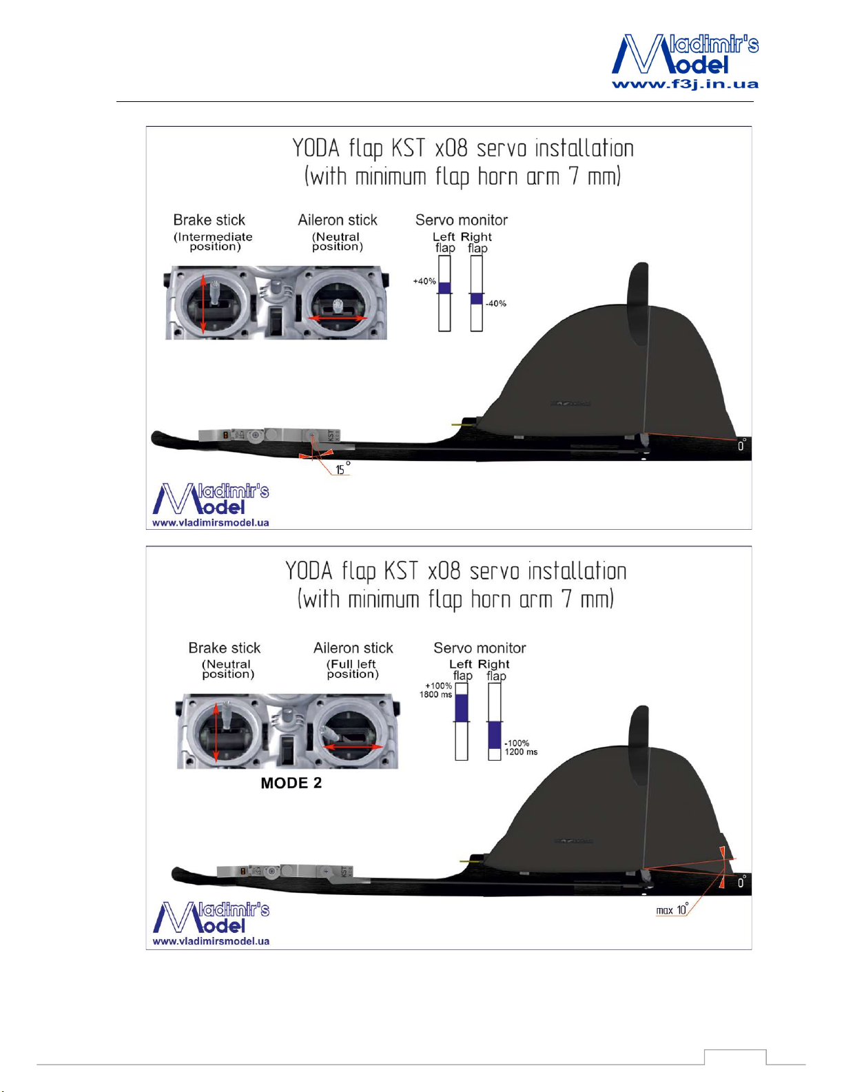
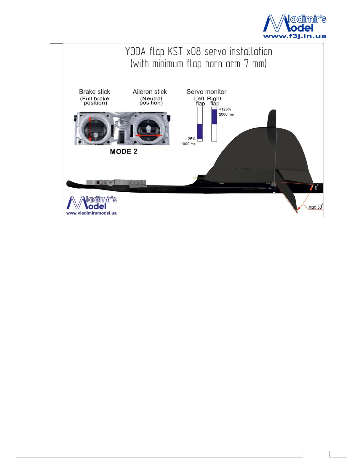
3. Radio-control installation
18
Page 19
YODA
Recommendations for assembly
19
 Loading...