

Page 1
SNIPE 2 EL
Recommendations for assembly
‘’
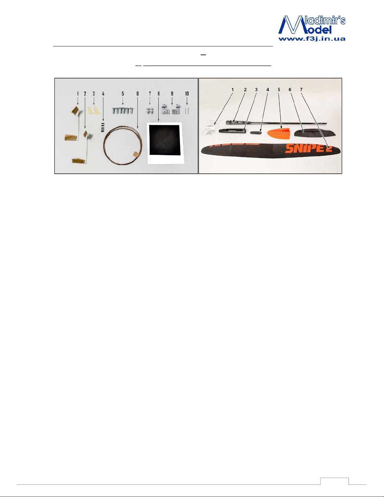
1. The list of parts and materials to build:
Accessory kit: Parts set:
1. Elevator spring;
2. Rudder spring;
3. Snipe 2 electric elevator and rudder control horns;
4. Pipes for the fixing control cables (1pc is spare);
5. Screws for wing and rudder M3x10 ( 3pcs are spare)
6. Snipe elevator and rudder control steel cable;
7. Snipe 2 aileron ball head aluminum screws (2 pcs);
8. Carboline SC 78 4/30 carbon for fixing aileron horn
pins;
9. Snipe 2 aluminum aileron control horns set (left and
right);
10. Aileron horn pins (2 pcs).
The list of materials needed to build the model:
1) Superglue and liquid medium, the accelerator
2) Cutter
3) Masking tape
11. Accessoires of Snipe 2 El kit;
12. Tail boom;
13. Fuselage;
14. Canopy;
15. Rudder;
16. Horizontal stabilizer;
17. Wing.
4) Pen and ruler
5) Pliers
6) Sandpaper number 240-320
1
Page 2
SNIPE 2 EL
Recommendations for assembly
2. Assembling the model
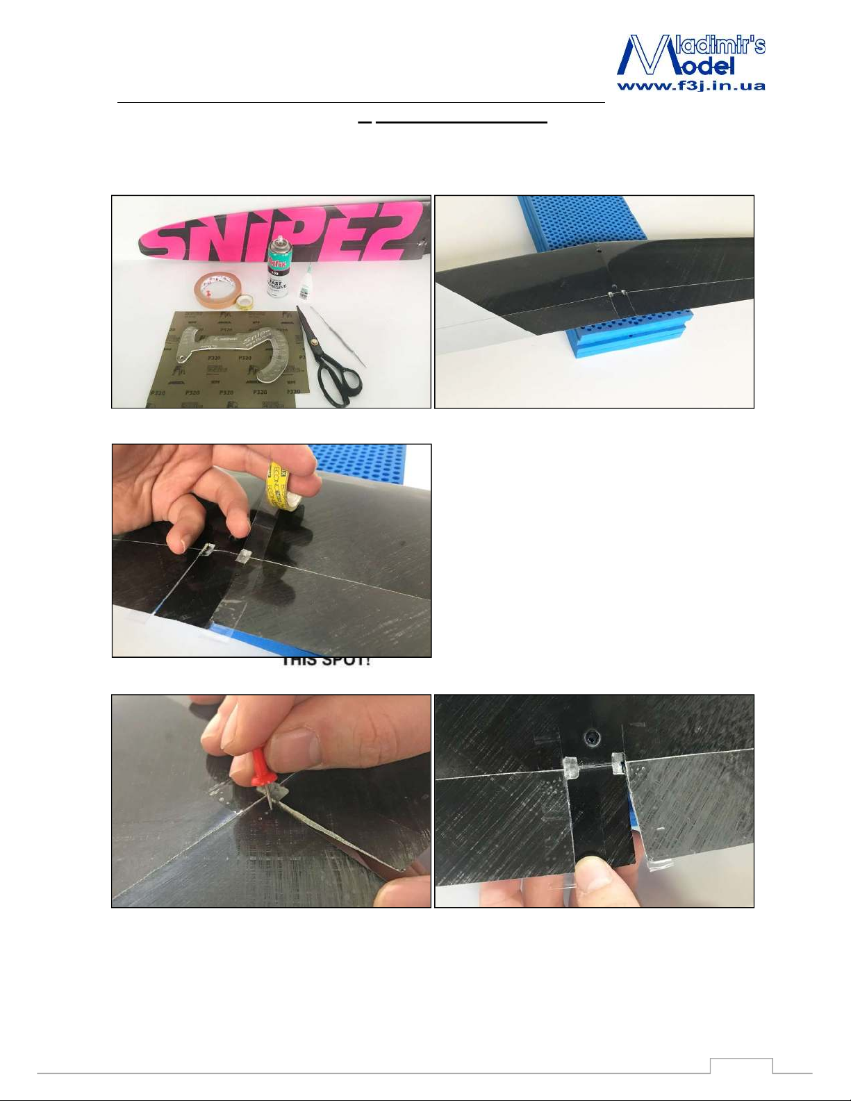
2.1 Aileron horns installation.
This is very important sequence to follow for successful control installation.
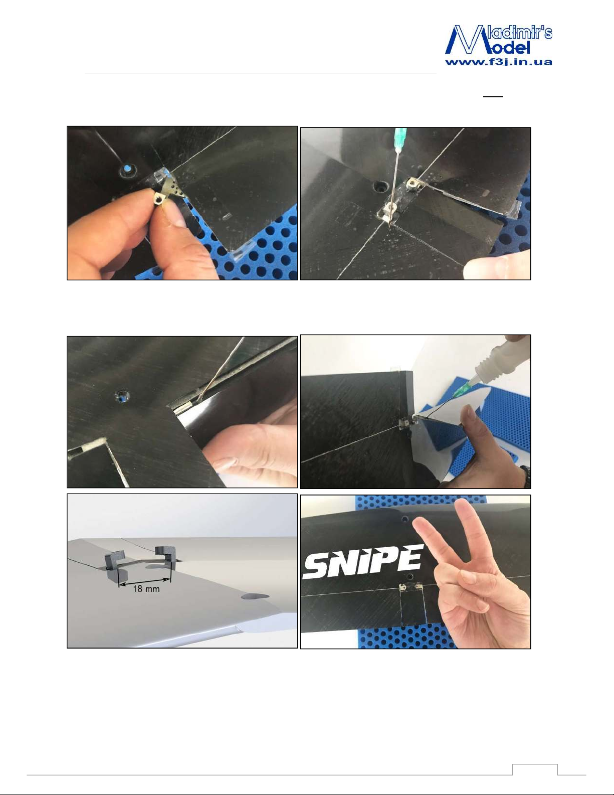
Place a small piece of tape on bottom of flap over
control horn and make small hole in flap with pin for
glue hole.
CAUTION!
Gluing zone of aluminium horn is covered with
primer for epoxy and CA!
2
Page 3
SNIPE 2 EL
Recommendations for assembly
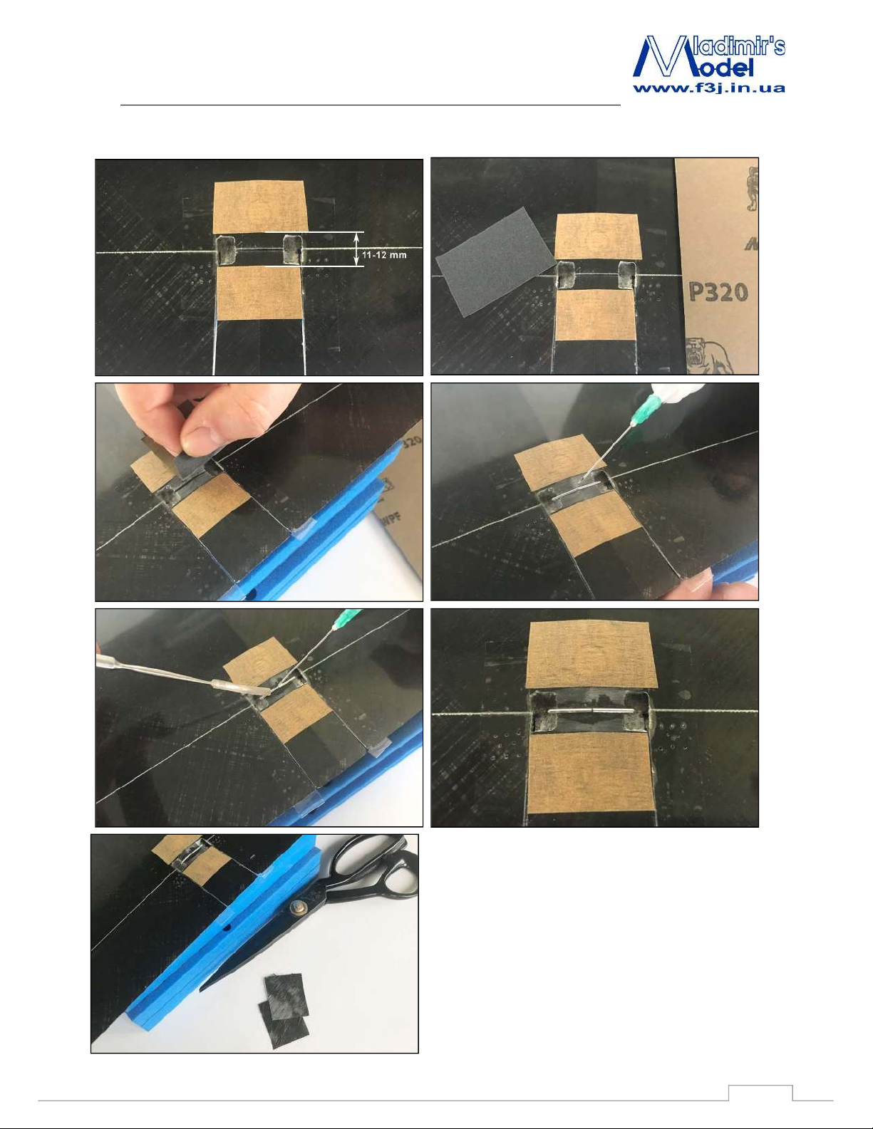
Glue pins in groves at bottom of wing.
Reinforce aileron’s pins by 2-3 layers of Carboline
SC 39 2/45 (8x14 mm).
3
Page 4
SNIPE 2 EL
Recommendations for assembly
4
Page 5
SNIPE 2 EL
Recommendations for assembly
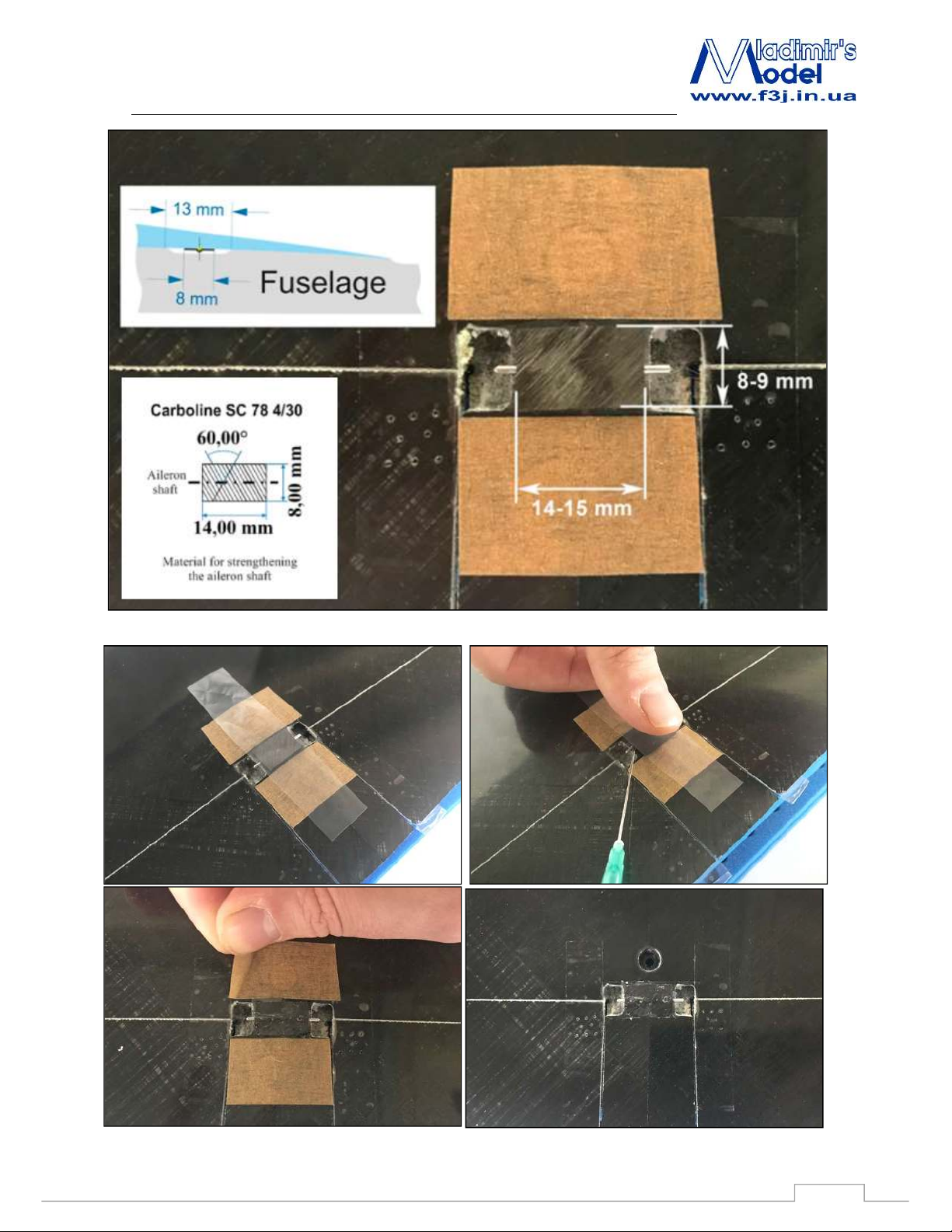
Then slide control horn into slot in flap. Next, slide control horn on pin and push horn to inside edge of hole,
toward center of wing. Leave just enough clearance between horn and hole so the horn does not scrape edge of
hole.
Use some thin CA and drip glue into pin hole. When CA is dry, remove tape. Pull flap down and fill space
around control horn with CA.
5
Page 6
SNIPE 2 EL
Recommendations for assembly
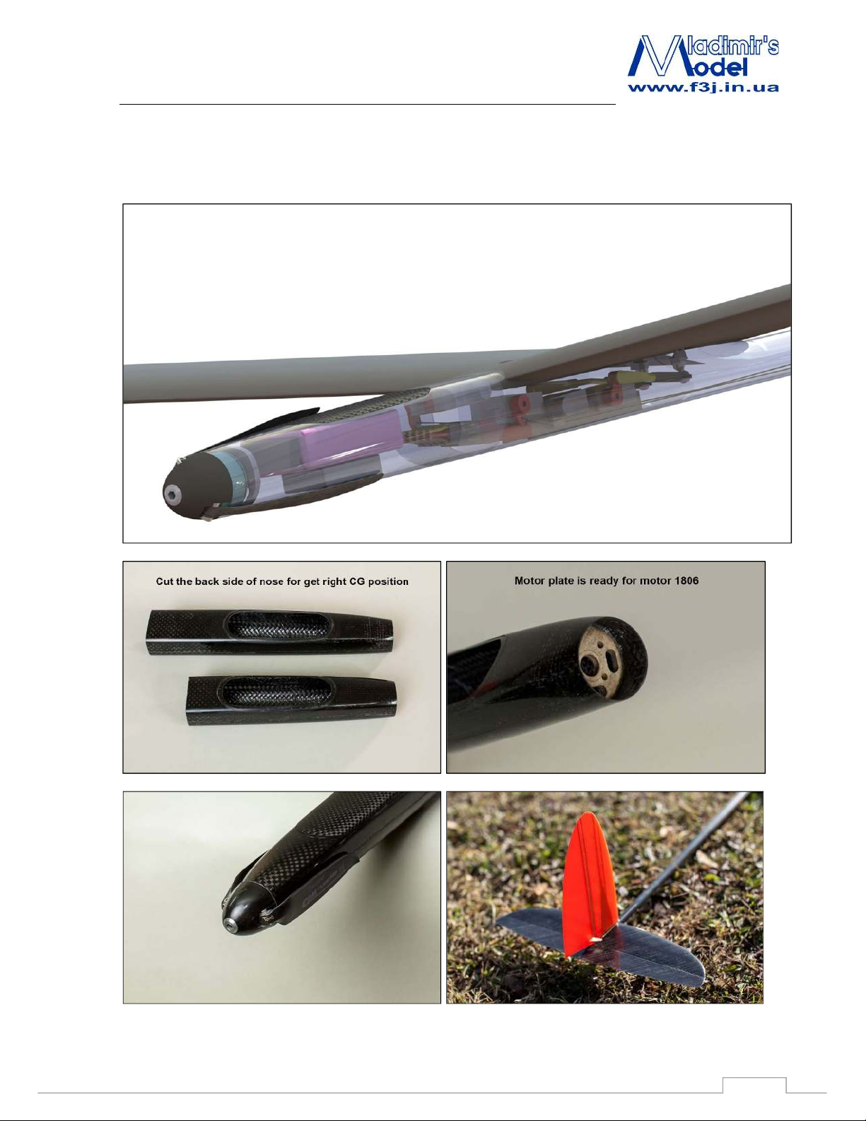
2.2 Snipe 2 EL Fuselage.
6
Page 7
SNIPE 2 EL
Recommendations for assembly
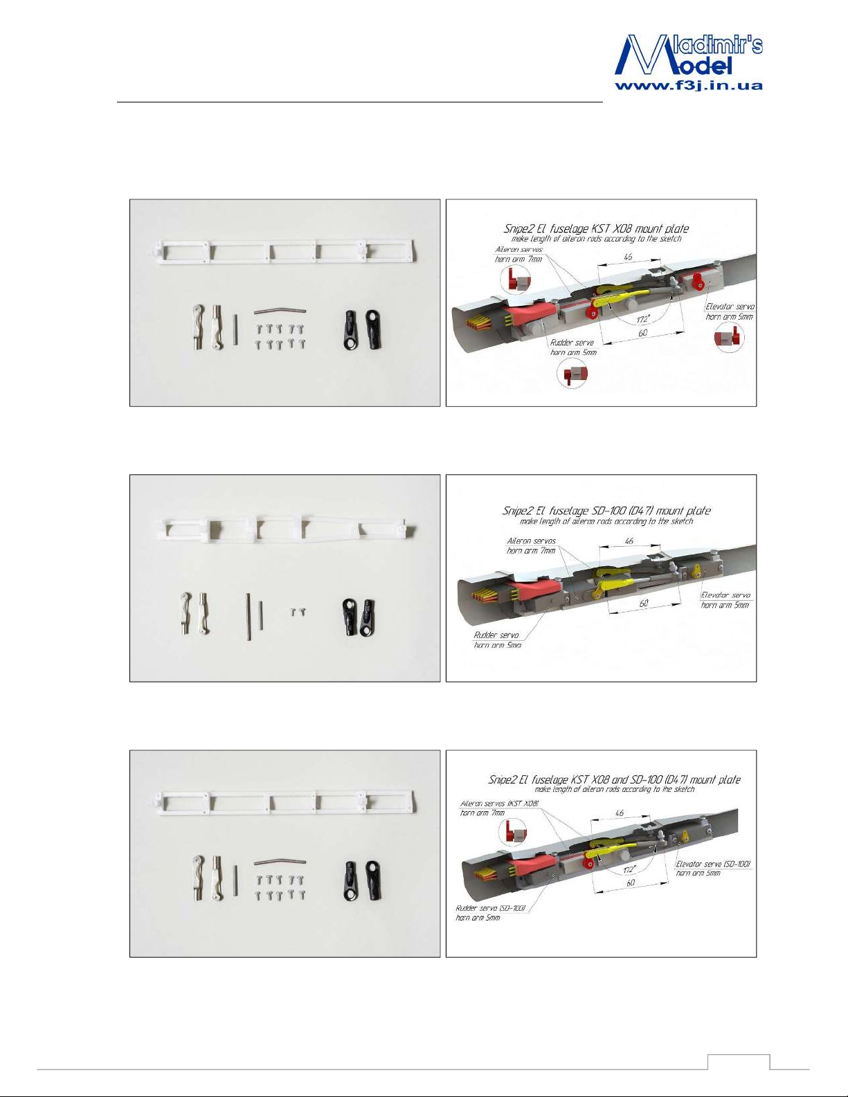
2.3 Snipe 2 Electric fuselage KST x08h mount plate
Snipe 2 Electric fuselage D-47 (SD-100) mount plate
Snipe 2 Electric fuselage KST X08 and SD-100 mount plate
7
Page 8
SNIPE 2 EL
Recommendations for assembly
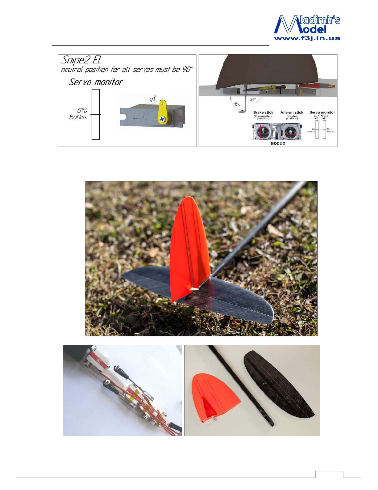
2.4 Snipe 2 EL Tail
8
Page 9
SNIPE 2 EL
Recommendations for assembly
2.4.1 Installation of torsion springs and horns
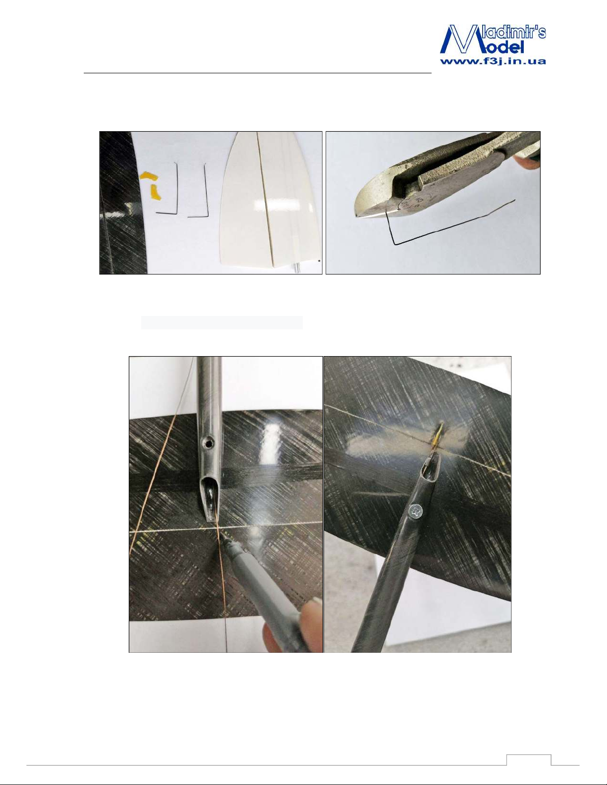
Сut the sides of the torsion bar, which will be located in the rudder and elevator. Leave 15mm length.
Install the stabilizer to the fuselage to mark the position of the elevator horn. You can use paper
tape to better see the mark. Control cable should be along the left side of the fuselage, as left as
possible: the cable should pass by the fin spar. Make an incision with knife and insert elevator
horn. Fix with CA.
9
Page 10
SNIPE 2 EL
Recommendations for assembly
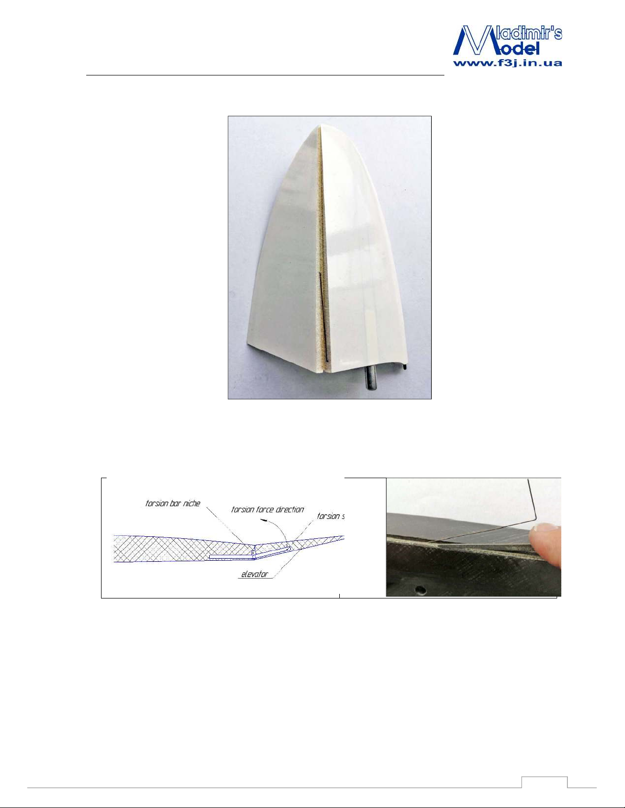
Rudder torsion spring: Set the rudder torsion spring as shown in the picture.
Elevator torsion spring: Scratch the torsion bar niche as shown in the sketch. Insert torsion
spring to the elevator. ATTENTION! Snipe 2 EL torsion spring have to pool elevator up! It works
in the opposite direction compared to Snipe 2 DLG. The right direction is shown in the sketch
below.
10
Page 11
SNIPE 2 EL
Recommendations for assembly
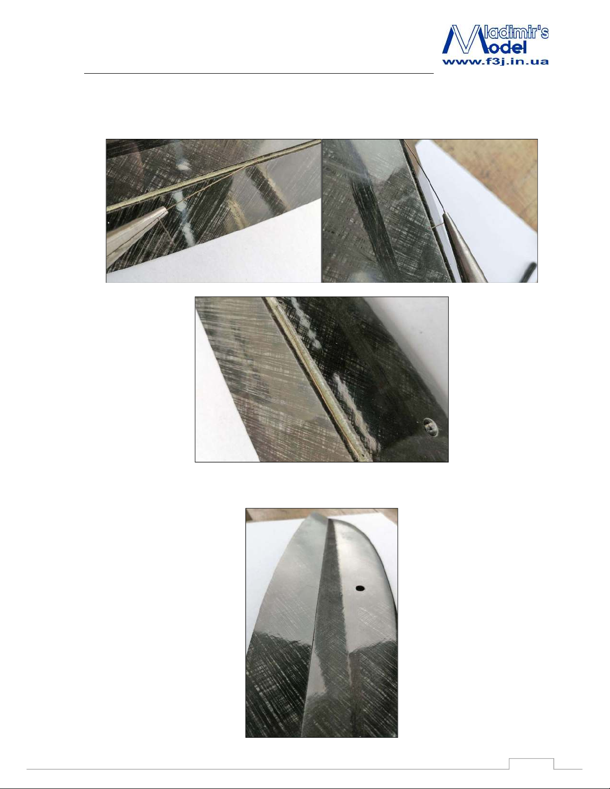
To complete the installation of the torsion spring, you need to bend down the elevator. Twist the
torsion bar with pliers and insert into the stabilizer
Torsion bar is installed correctly if the gap on the upper surface of the stabilizer closes with
torsion loading.
11
Page 12
SNIPE 2 EL
Recommendations for assembly
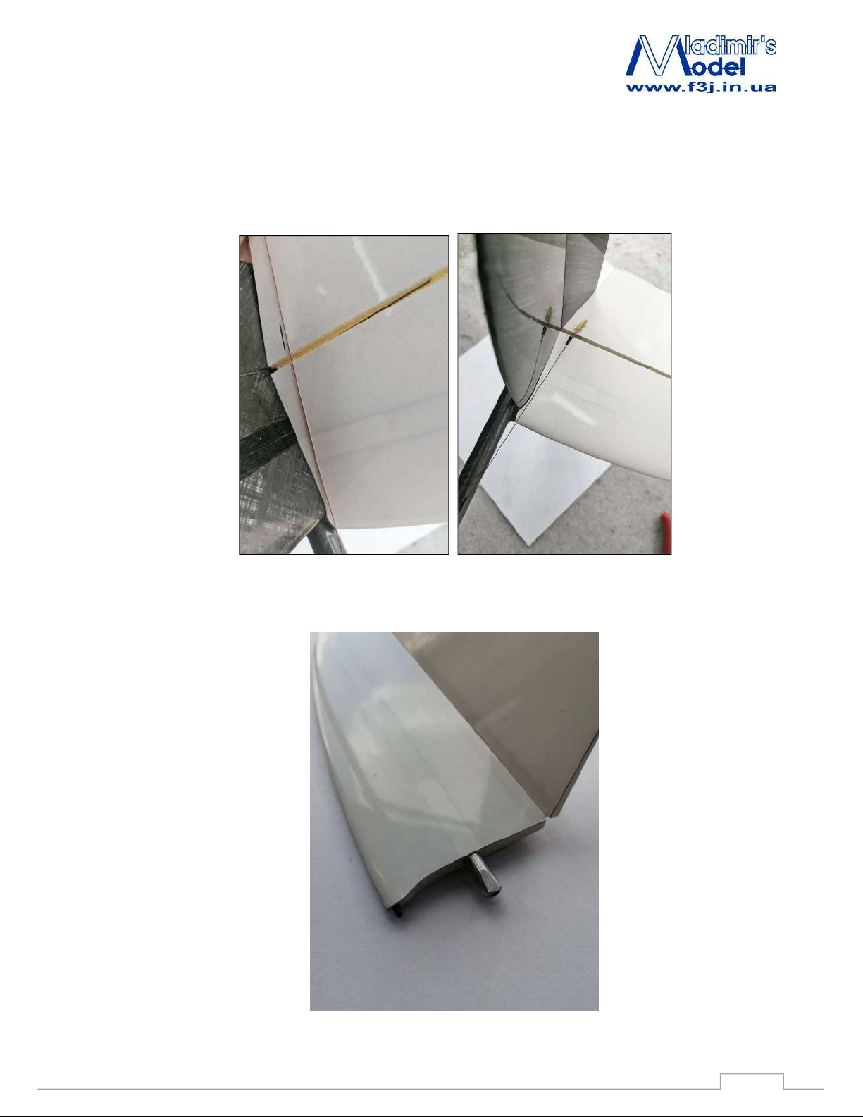
To install the rudder horn, assemble the tail and pull the control cable of the rudder 2 mm above
the horizontal stabilizer. Draw a mark along the control cable. You can use paper tape as well as
for marking the elevator horn. Make an incision with knife and insert rudder horn. Fix with CA.
Сut off the aluminum part of the horizontal stabilizer as shown in the picture. This will
prevent damage to the control cable when assembling the tail.
12
 Loading...