

Page 1
Snipe
Recommendations for assembly
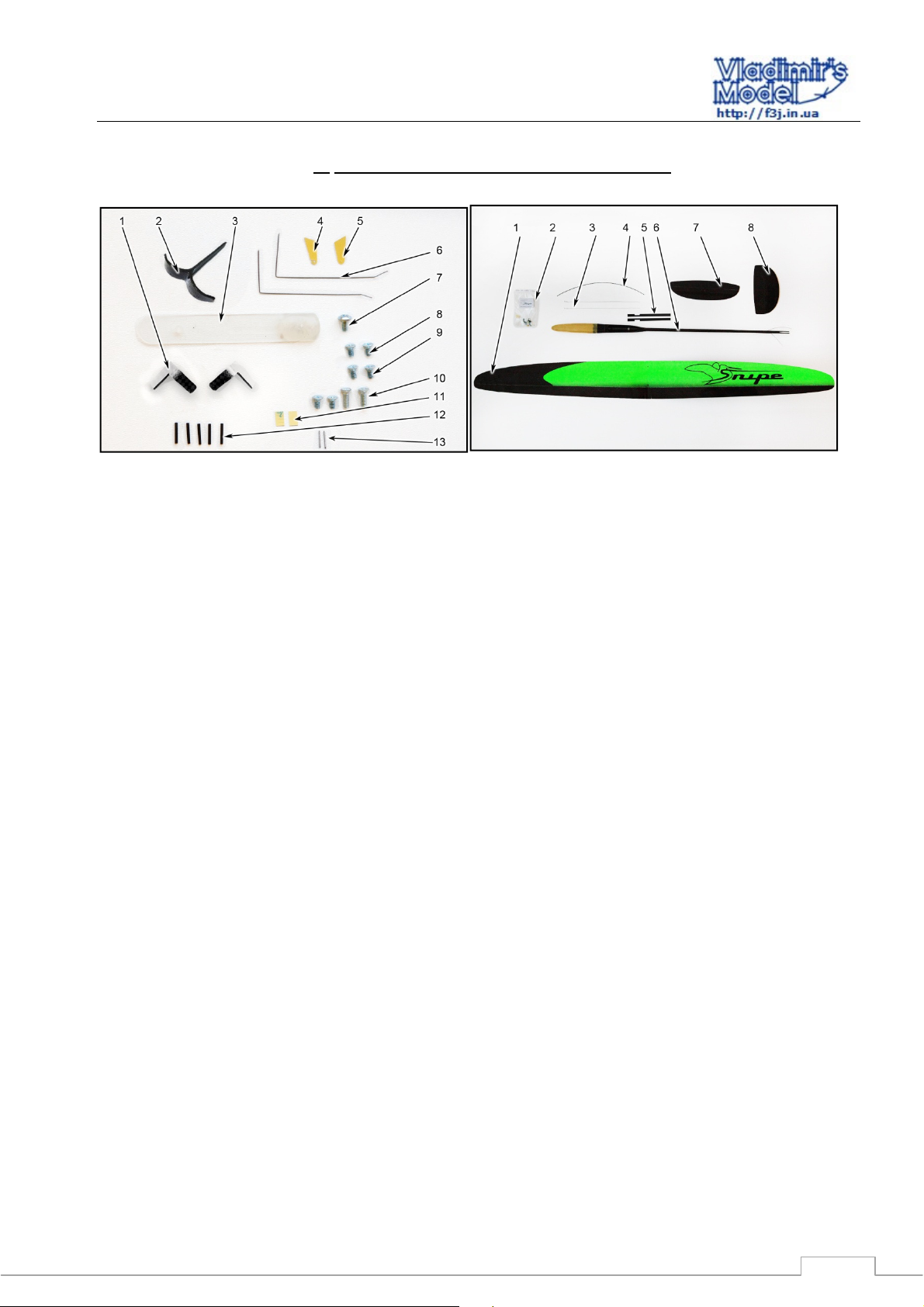
The list of parts and materials to build:
1.
Accessory kit: Parts set:
1 - Horns wing (2 pcs);
2 – Launch T peg;
3 – Ballast nose mount;
4 - Stabilizer control horn (with slot)
5 – Vertical tail control horn (with hole);
6 - Torsion spring rudder and elevator;
7 - Screw for ballast M3;
8 - Screws stabilizer (2 pieces);
9 - Spare screws stabilizer (2 pieces);
10 - Set of screws for attaching the wing and M3 h10 M3x6
(1 set of spare);
11 - Cover wing controls;
12 - Pipes for sealing control cables;
13 – Flaperon control horn pivot axes.
1 - Wing;
2 - Accessory Kit Snipe;
3 – Flaperon pushrod (2 pieces);
4 – Flaperon pushrod housing;
5 - Fuselage;
6 – Flaperon pushrod stiffener plate;
7 - Stabilizer;
8 – Vertical tail.
List of recommended hardware to run your model:
1) Ballast Snipe;
2) Battery Shread-RC Smart Li-Po 650mAh or Shread-RC Smart Li-Po 450 mAh
3) Servos: JR 285 MG, FutabaS3155, MKS-DS6100, HyperionDS09-SCD, DymondD60; DymondD47 (Only the rudder);
4) Receivers: Spectrum AR6255; Futaba 6008HS without the case; Futaba R6106HFC; Weatronic Clever 6 Receiver
2.4 Dual FHSS.
The list of materials needed to build the model:
1) Superglue and liquid medium, the accelerator
2) Cutter
3) Masking tape
4) Pen and ruler
5) Pliers
6) Sandpaper number 240-320
1
Page 2
Snipe
Recommendations for assembly
Assembling the model
2.
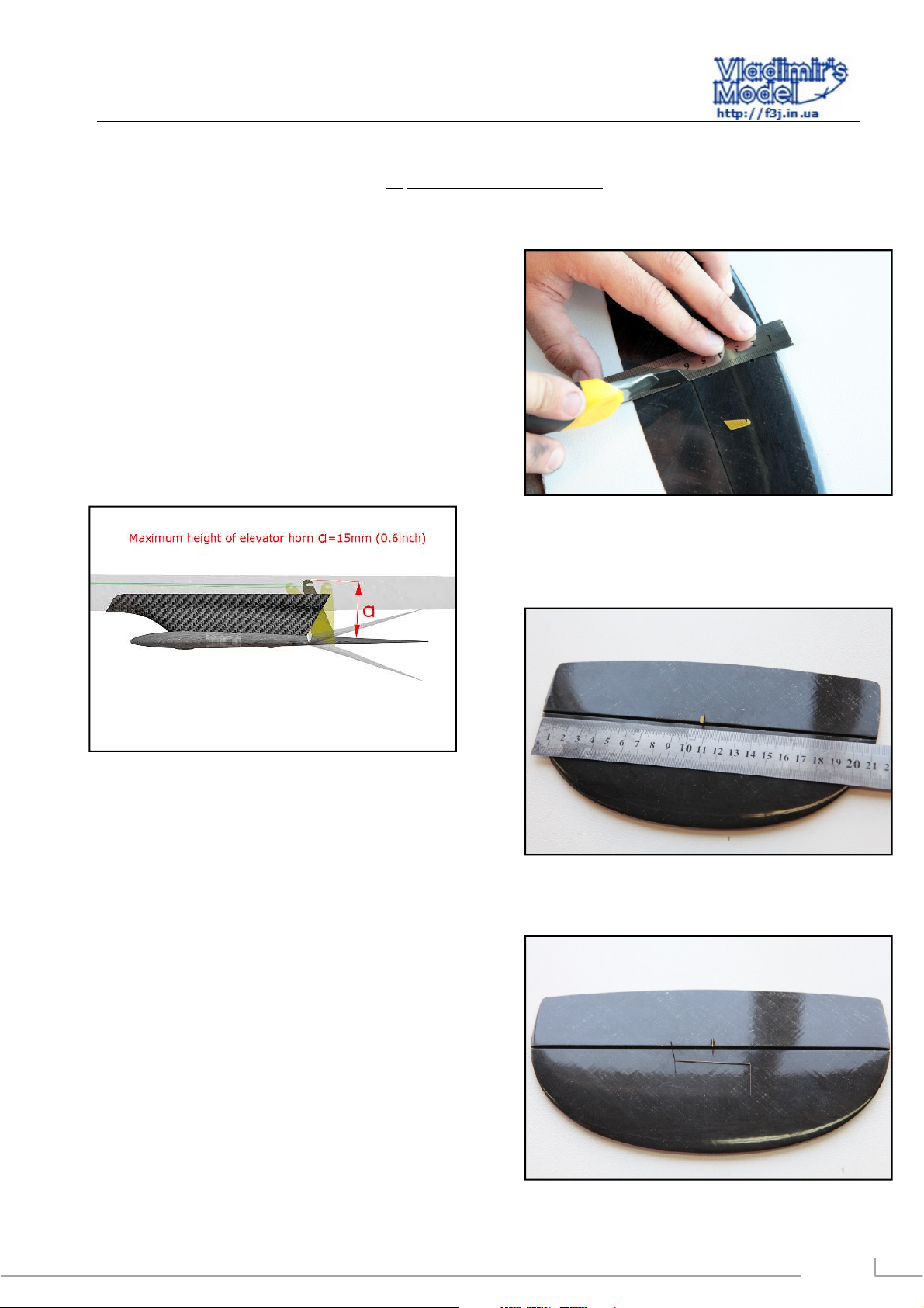
2.1 Bonding of control horns in rudder and elevator.
With a knife cut the slots in the elevator and rudder in
these locations. (Fig. 2.1 - 2.2).
Elevator horn isexactly in the center (along the axis of the
stabilizer mounting holes) as the position must coincide with
the slot in the pylon and tail boom. Horns must be glued full
depth to elevator.
Liquid superglue Glue Horns in elevator and rudder..
Note:
- the maximum height of the elevator horn is 15 mm
(Fig. 2.3)
Figure 2.1 - Bonding elevator horn
Figure 2.3 - Maximum elevator horn length
2.2 Bonding of torsion bars in the control surfaces
Center torsion spring on the control surface. (Fig. 2.4)
Make holes for the torsion spring with a needle and install
torsionspring with superglue. (Fig. 2.5, 2.6) Torsion spring
should provide force to the opposite side of the control horn.
Figure 2.2 – rudder horn installation location
Figure 2.4-Torsion spring location
2
Page 3
Snipe
Recommendations for assembly
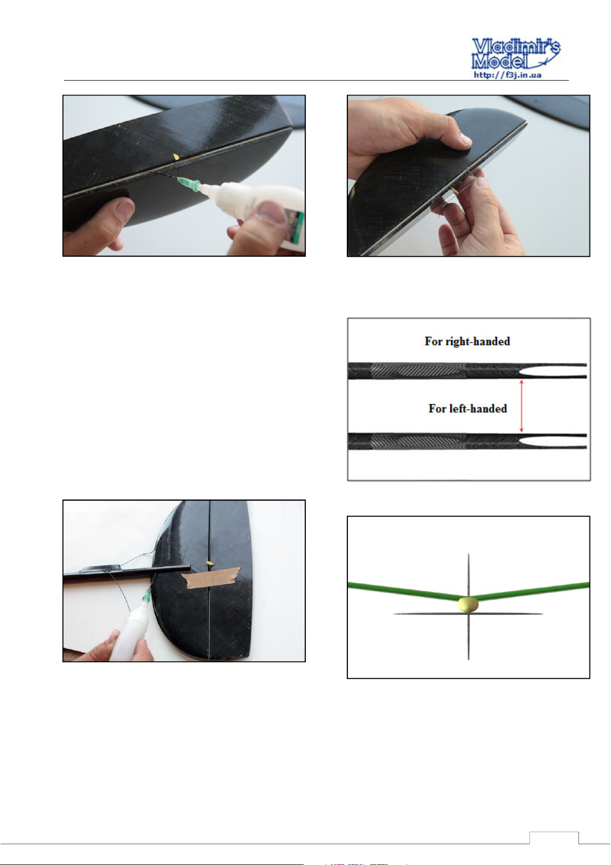
Figure 2.6 - Sizing torsion feathers
2.3 Inset kylya in hvostovuyu beam
Fix the rudder at zero deflection with masking tape.
For the vertical tail, install it vertical relative to the
stabilizer and wing (Fig. 2.8), and center it with respect to the
boom. (JW note: I offset mine about 1 cm upwards compared
to centered). Glue the fin into the groove of the fuselage with
superglue. (Fig.2.9)
(JW – I put a small fiberglass patch over the fuselage onto
the fin to increase the durability of the fin bond)
When bonding fin note:
- because airfoil is not symmetric, we make two versions
of the fuselage keel with grooves right-handed and lefthanded. Fig. 2.7 shows a view on the fuselage below
Figure 2.5 - Insert the torsion bar in the tail
Figure 2.7 - Two versions of the fuselage (bottom view)
Figure 2.9 – Bonding fin
Figure 2.8 Set fin perpendicular to the axis of the fuselage
3
Page 4
Snipe
Recommendations for assembly
2.4
Incorporation of tail surface control cables
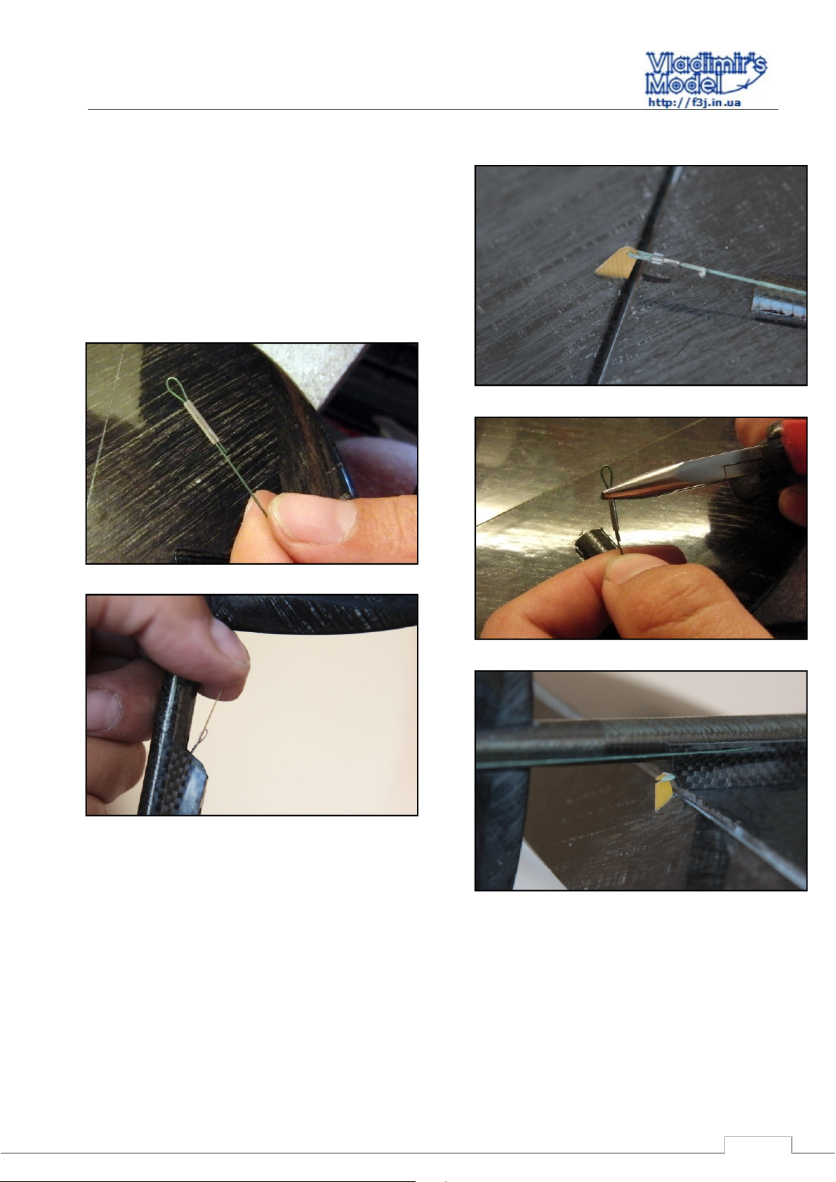
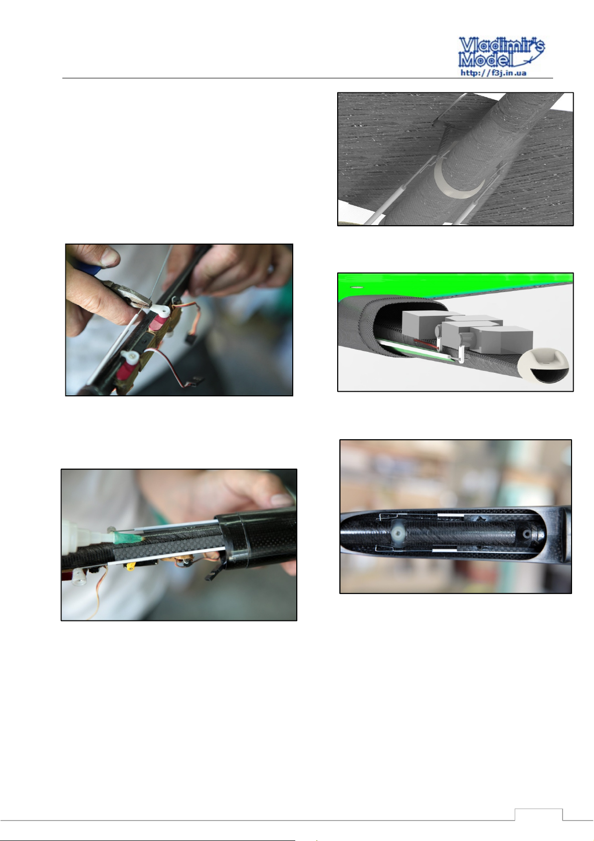
Insert the wire through the hole on the control horm. Using
a tube for cables (which you'll find in the accessories kit) with
a pair of pliers to crimp the cable as photo 2.10-2.11
To make a draft of the stabilizer of a cable loop and crimp
its tube for fixing the rope. (Fig. 2.12, 2.13).
For assistance in assembly, attach a 100 mm thread to the
elevator cable. You can lock the thread on the tail boom with
tape and pull it out of the slot in the fuselage for assembly of
the model. (Fig. 2.13)
Figure 2.12 - Preparation for the cable stabilizer
Figure 2.10 - Cable on rudder
Figure 2.11 - Crimping tube cable
Figure 2.13-The thread on the cable of the elevator
Fig. 2.14 - Cable stabilizer
4
Page 5
Snipe
Recommendations for assembly
2.5 Installing the aileron horns.
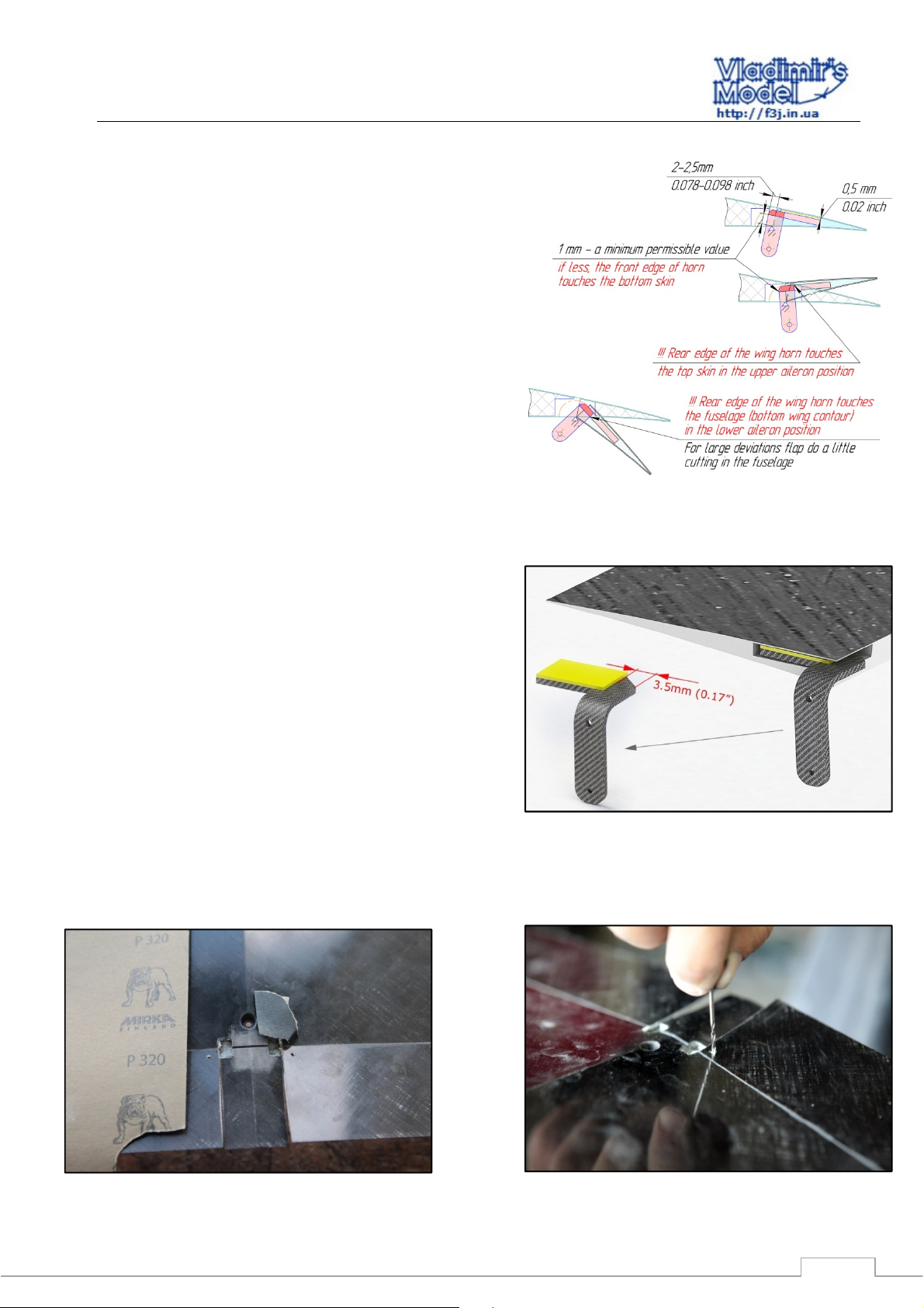
Attention: Snipe wing pylon has a complex kinematics.
Installing the horn the wrong location in the depth and the
chord of the wing there can be interference with the upper
wing skin. Fig. 2.15
In order to provide clearance from the upper surface of the
wing patch stick to the pylon . Attach the patch to the upper
flat of the flaperon horn tab. Fig. 2.16
Drill a hole with a diameter of 2- 3mm in the lower surface
of the wing in the control horn, to prepare horn installation
with glue . Fig. 2.17
Clean the area around the flaperon pivot axis slot and
sandpaper for better adhesion . Fig. 2.18
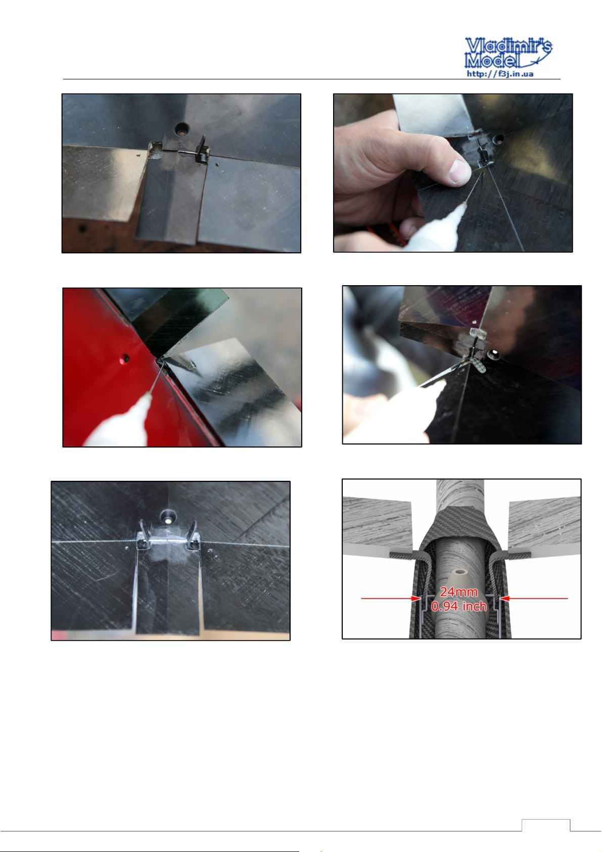
Insert the Horns in the slot of the flaperon , and insert the
pivot shaft into the flaperon horn. Secure the axle in the wing
slot with superglue . Fig. 2.19 Make sure that the horn
separation matches Fig. 2.24
Set the pylon in the gap of 0.3-0.7 mm from the stop line.
Set the plane parallel to the plane of the slot hog inside the
aileron . Lock Horns with thick superglue through the hole.
Use the accelerator , but do not let the foaming superglue .
Fig. 2.20
Turn the aileron carefully seal the pylon inside the aileron .
Be careful - do not pour glue joint elerona. Fig. 2.21 Kevlar -
2.22
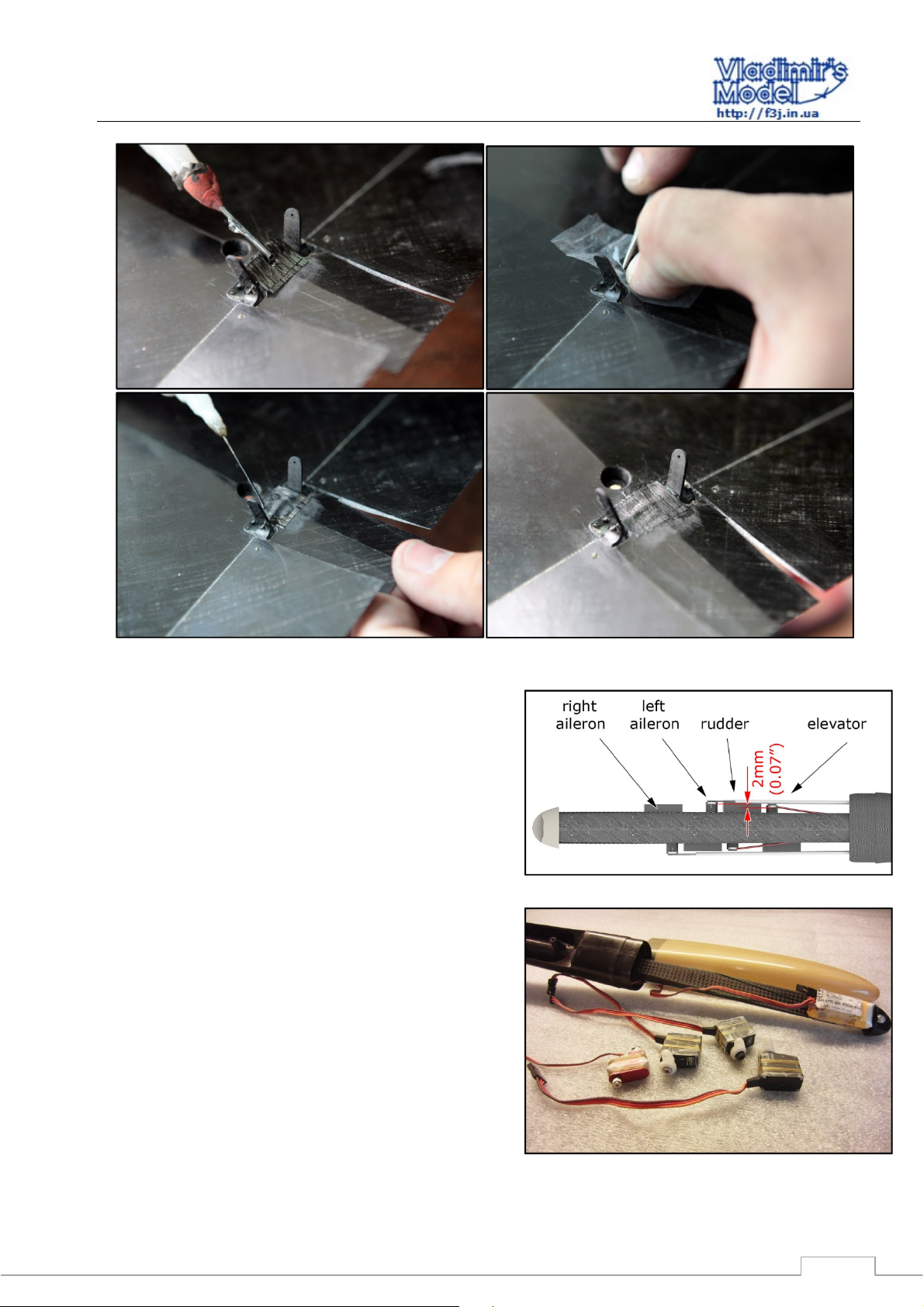
Cut carbon tissue ( 80-120 g/m2) or two layers of
Carboline. Glue the reinforcement , alternating impregnation
CA and crimping finger through a polyethylene film. Be
careful not to use too much CA and glue pylon axis . Fig.
2.25.
(JW note: I used good epoxy for these steps rather than
CA)
Fig. 2.15 - Kinematics aileron horn
Figure 2.16 – Flaperon horn tab insert
Fig. 2.18 – preparing axle bond with sandpaper
Figure 2.17 - Holes for gluing horn in flaperon
5
Page 6
Snipe
Recommendations for assembly
Figure 2.19 – Gluing the flaperon axles
Figure 2.20 - Bonding horns thick CA through the hole in the
aileron
Figure 2.21 - Bonding horn inside the aileron
Figure 2.23 - Finished Horns wing with pivot axles
Figure 2.22 - Bonding horn inside the aileron
2.24 - The distance between the flaperon horns
6
Page 7
Snipe
Recommendations for assembly
Figure 2.25 - Bonding gain axis hogs wing
2.6 Installing the servos, battery and receiver
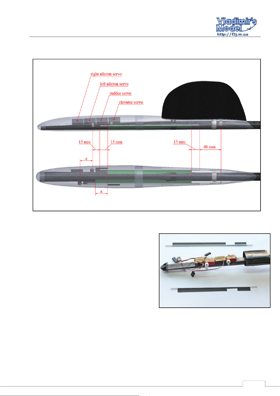
Recommend placing the equipment in the manner as
shown in Fig. 2.26 . Minimize nose weight by installing the
gear as far forward as space will permit.
To save space, we recommend trimming the servo mount
tabs so the servos can be pushed together. One can wrap the
servos with masking tape to aid in replacement (JW note, I
find it easier to not do this as the glue pops easily from the
plastic servo case when one needs to replace a servo).
Carefully wrap the servo case with strong thread ( Kevlar or
other CBM ) (Fig. 2.27).
Prepare Horns Servo with arm lengths:
The ailerons - 9 -11mm (JW – I use 6-7 mm);
The elevator and rudder - 8 -9mm . (JW – I use 7 mm)
Screw the Horns to the servo.
Secure the battery in place in the nose with adhesive tape.
Secure the receiver in place with double sided adhesive tape.
Horns aileron servos should be further away from the fuselage
body and tail servo horns closer (Fig. 2.26). Place the receiver
at the front of the fuselage fairing (aft of the servos).
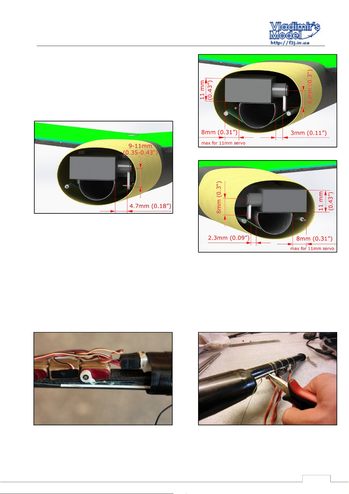
Attention: If you are using a servo thickness of 11 mm,
pay attention to the location to ensure that there is no
interference with the nose cone. (Fig. 2.28 -2.30).
Put the nose cone and check that it is worn and does not
interfere with the installed radio gear.
Figure 2.26 - Placement of equipment in the nose Snipe
Fig. 2.27 - Preparation of the servo to the foldout
7
Page 8
Snipe
Recommendations for assembly
Screw the wing and check the resulting center of gravity of
the model. (68mm from the leading edge [JW – start with 62
mm!]) Adjust it by moving the receiver and the battery
forward or back. (JW –AKA, by adusting noseweight!!)
The gear can now be bonded to the fuselage, leave the
battery removable. (Fig. 2.27)
Figure 2.30 - Left aileron servo installation (right aileron servo is
mirrored)
Figure 2.28 - Placement of the elevator servo
2.7 Attaching cables to the servo control.
Set the Horns machines upright handlebars and pull the
rudder cable through the servo and back through the crimp
tube. Tension cable to set neutral rudder. Crimp the tube
with pliers. (Fig. 2.31-2.32)
Repeat cable tension and crimp for elevator.
Figure 2.29 – Rudder servo installation
Figure 2.32 – Wire on the horn of servos
Figure 2.31 – Crimping of tube for tail control
8
Page 9
Snipe
Recommendations for assembly
2.8 Installing the aileron pushrods
Figure 2.33 - Install the aileron linkage and the supporting carbon plates (green)
Cut the flaperon tube housinge and carbon fiber plates in
length, as shown in ( Fig. 2.33 )
Glue the tube to the edge of the carbon plate with
superglue . ( Fig. 2.34)
Insert the flaperon control rod/tube assembly into the
fuselage .
Connect the pushrod to the aileron horns . Pay attention to
the correct direction of the linkage. ( Fig. 2.35 )
Screw the wing (use screw M3H10 for front fastening and
M3x6 for the rear ) .
The pushrod should be straight to get a direct connection
between the servo and the flaperon horn . Pay attention to the
how the rod will be bent for the insertion in the servo .
( Fig. 2.36 )
(JW – I recommend that the flaperon servo horn be angled
aft by about 15-20 deg when the flaperon is neutral, this
provides sufficient movement for landing flap deflection)
Tape the control surface in a neutral position. Bend the
rod 90 degrees to insert into the servo control horn. Trim
excess rod length and insert rod into servo horn.
Turn carbon sheet to contact the fuselage tube and
superglue it, as far as possible under the cowl. Ensure that
Figure 2.34 – Flaperon housing tubes with reinforcing plates
9
Page 10
Snipe
Recommendations for assembly
both ends have sufficient movement range for full control
surface movement prior to bonding( Fig. 2.38 )
(JW – after linkage mfg, I put a load on the control surface
such that the rod is in tension prior to gluing the sheet to the
fuselage tube, this ensures that the rod is straight)
Remove the wing and bond the remaining carbon sheet
inside the fairing to the fuselage . ( Fig. 2.39)
(JW – I put a small z-bend in the pushrod wire so the the
wire is centered in the middle of the control horn. I do this for
both ends of the wire)
Figure 2.35 - Direction tip aileron linkage
Figure 2.37 – Closing up of aileron pushrod tip on servo side
Figure 2.38 – Gluing flaperon stiffening carbon sheet
Figure 2.36 - Closing up of aileron pushrod tip on servo side
Figure 2.39 - Fixing the aileron linkage inside the fairing
10
Page 11
Snipe
Recommendations for assembly
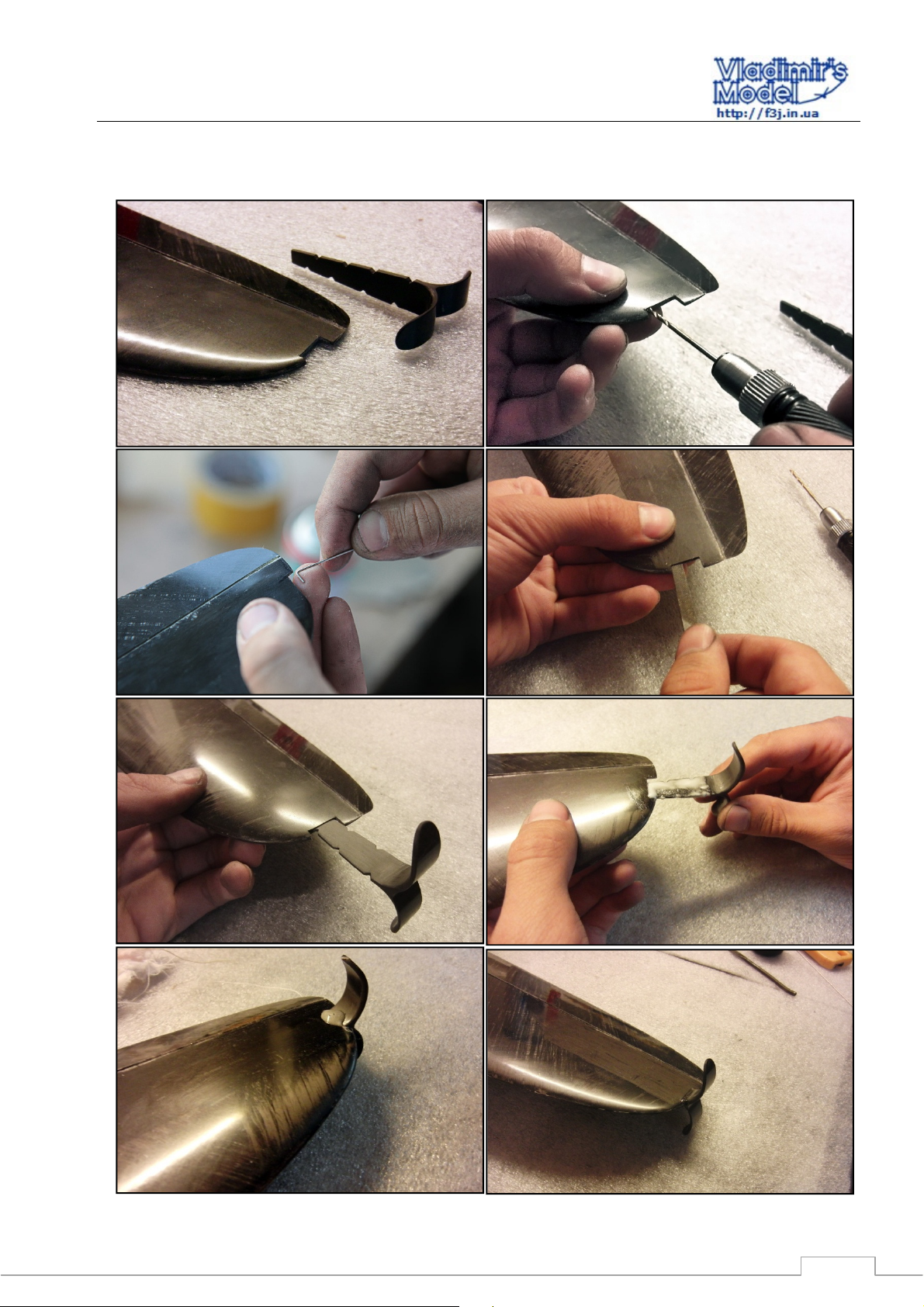
2.9 Insert a pin to roll into the wing
11
Page 12

Snipe
Recommendations for assembly
12
 Loading...