


VKAR SCT X10 PRO
INSTRUCTION MANUAL
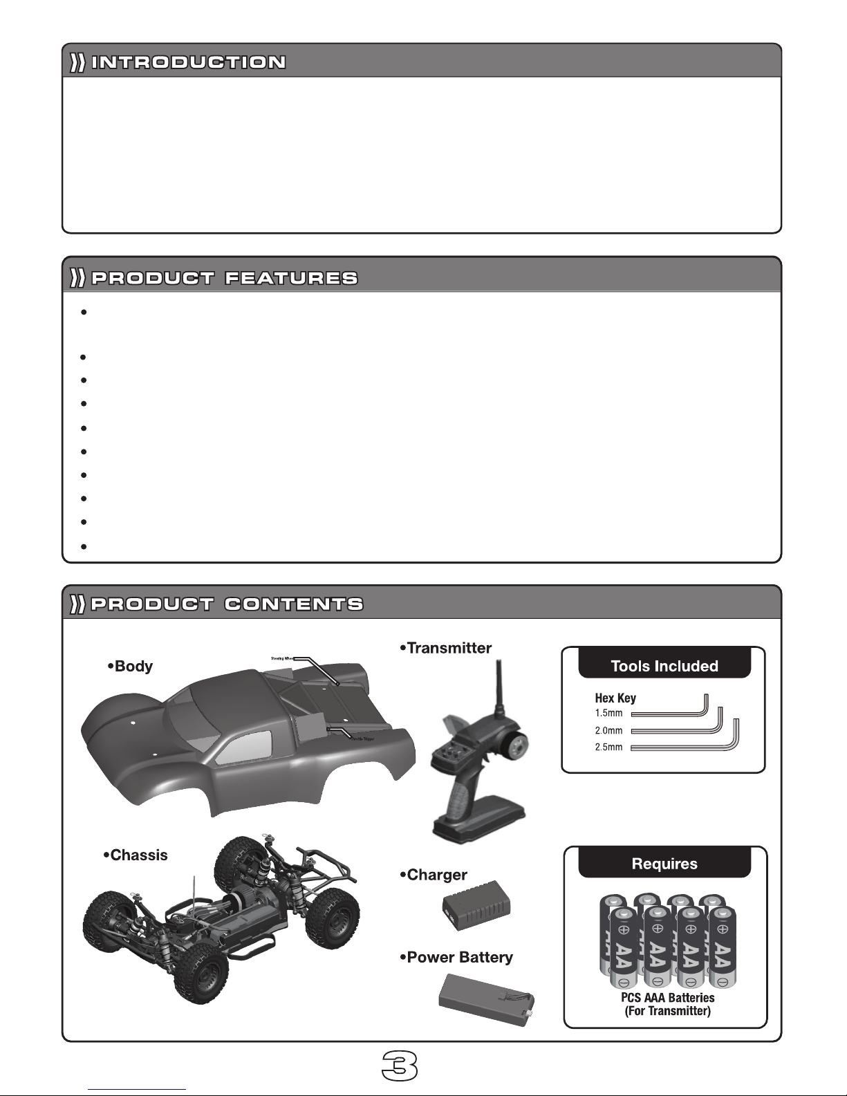
Lowers chassis 7.3mm.Low center of gravity enhances handling and
increases cornering speed.
Durable,anodized,hairline-finish aluminum chassis.
Easy-adjust motor mount,quickly adjust the gear pitch.
Aluminum,adjustable,big volume,oil-filled,coil-over shocks.
Three sealable differentials.
Scaled all-terrain front and rear tires for superior on and off-road traction.
Telescoping universal joint driveshaft.
Aluninum 12mm wheel hexes.
Pitch pinion gear and spur gear with slipper clutch.
Painted and decaled short course racing body.
Thank you for purchasing this Vkar racing model.This manual contains instructions on
operating and maintaining the Vkarx10 PRO.Please take a monent to read through this
manual to familiarze yourself with this model.
Vkarx10 PRO is a pure Water-Proof short-course thuck designed by Vkar with an one-piece
tub chassis.The design batter prontects the electronic components and driving system.
8
33
10 PRO
44
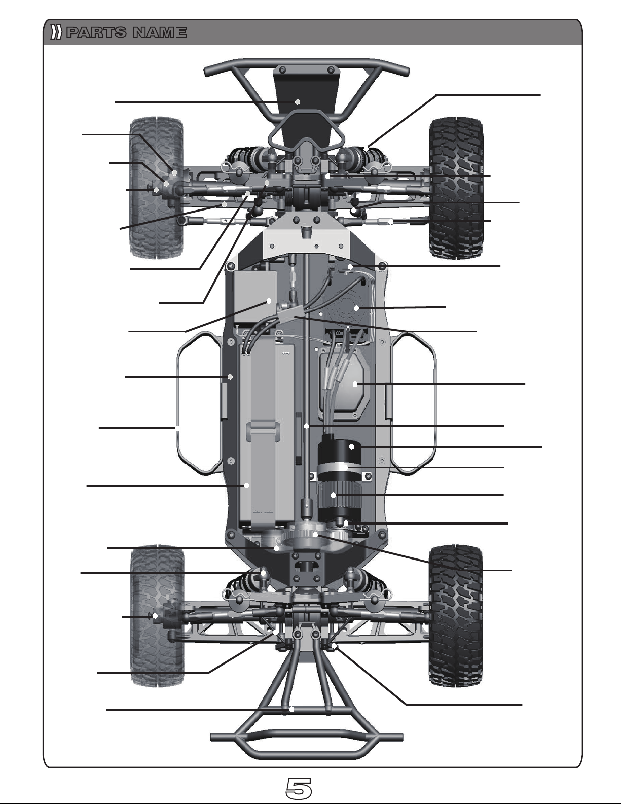
Front Bumpr
C-hub
Steer Block
Wheel Hex Hub
Universal Joint
Body Mount Bracket
Steering Servo
Side Bars
Battery
Base support frame
Dust Guard
Rear Hub Carriers
Sway bar
Rear Bumpr
Motor Mount
Motor
Center Shaft
Receiver
Battery Connector
Electronic Speed Control
Power Switch
Turnbuckle Rod
(Camber Link)
Arm Hold
Shock
Front Shock Stay
Suspension Arm
Shock
Sway bar
Spur Gear
Motor fixator
Motor radiator
PARTS NAME
55
66
RADIO SYSTEM INSTRUCTION

77
Green
Green Led
Red Led
ELECTRONICS SRTUP
Model wiring diagram
In order to ensure the normal working of the electronic parts,
please check their connections regulayly.
NOTE:If connecting the battery in
opposite polarity,will damage the ESC.
Power Wire
Power
Model
Model wire
CH1
Steering Servo
Model wire
Receiver
CH2 ESC
Switch
Set Key
NOTE:After starting the motor,if the rotation
direction is out of your expection,please
change red of black wires arbitrarily.

Steering angle
is less
Steering angle
is more
88

First,connect the charger to an AC
power source
Secondly,connect the battery park
to the 2S balance port.
Charge for around 4-5 hours.
Loosen the straps and place the battery
Tighten the straps.
99
Cannect the Battery and ESC using the plugs.
Place(8) AAA batteries into the transmitter.
First,switch ON the Transmitter.
Second,switch ON the Car.
Put the body clips in
Use right hand to control the steering wheel and use left hand to
control throttle trigger.
1. Charging The Battery
2. Loading The Battery
3.Powering Up The Truck
4.installing Car Body
5. You can try to start your car now
.

64
82
55
55
65
70
69
68
66
67
70
74
75
73
72
71
71
72
72
72
71
82
64
83
84
86
85
84
87
30
12
30
88
84
84
83
82
64
T15Z
T15Z
1010
FRONT AND REAR DRIVE SHAFT ASSEMBLY DRAWING

103
98
92
While a screw fitting into a metal hole, it has to be stained
with some screw glue.
57
117
47
57
116
110
111
109
104
114
104
112
115
113
118
118
119
119
119
119
Note: 114 to rotate around.
99
FA R
NEAR
96
95
97
12
13
13
103
103
3
98
170
101
7
M3*18
M3*8
M3*25
M3*8
M3*8
M3*10
M3*3
92
7.5
166
100
168
168
167
1111

24
23
25
22
27
27
28
39
29
30
31
30
31
32
35
34
33
21
44
4
2
3
5
1
43
4
3
5
6
3
3
6
1
4
1.Fill the shock body with full silicone fluid(sold separately)
2.Pump the shock shaft up and down to remove any air bubbles.
3.After the air bubbles have been pumped out ,pull down the shock
shaft to the bottom.
4.Push the shock shaft up to the tip before pumping out the extra
silicone fluid.
5. Install the spring and the dustproof cover.
6. Shock assembly now complete.
165
1212

x1
1313
SPARE PARTS

x4
x2
x4
x2
x4
x2
x1
x1
x2
x2
1414
SPARE PARTS
SPARE PARTS

SW101
SW102
SW104 SW201 SW202 SW203
SW204 SW205
SW301 SW303
SW304 SW305
SW306
SW307
SW308 SW309
SW401
SW501
x10
x10
x10
IM3x3
IM3x12
IM4x8
KM2.5x8
x10
KM4x8
x10
KM3x8
x10
KM3x20
KM3x25
x10
x10
PM3x10
x10
PM2.5x4
PM3x12
PM3x16
x10
x10
x10
PM3x8
x10
PM4x12
x10
PM3x23
x10
PM3x6
x10
ZM3x12
x10
BM3x8
x10
NT102
NT103 EC101 EC102 EC103
NT101
x10
NYLON
FLANGED
x10
NYLON
x10
2.5mm
4.0mm
3.0mm
x10
x10
x10
OR101
x10
OR102
x10
OR104
x10
OR106
x10
OR107
x10
OR108
x10
ID 3.0x2.0mm
ID 4.5x1.5mm
ID 21.5x0.8mm
ID 12x2mm
ID 16x1mm
ID 37x1.5mm
ASSEMDLY PARTS
OPTIONAL PARTS
STADARD PARTS
1515
ES1071
MA372

MASC 4X4
EXPLOED VIEW
1616 1717

1818
BILL OF MATERIAL
 Loading...