

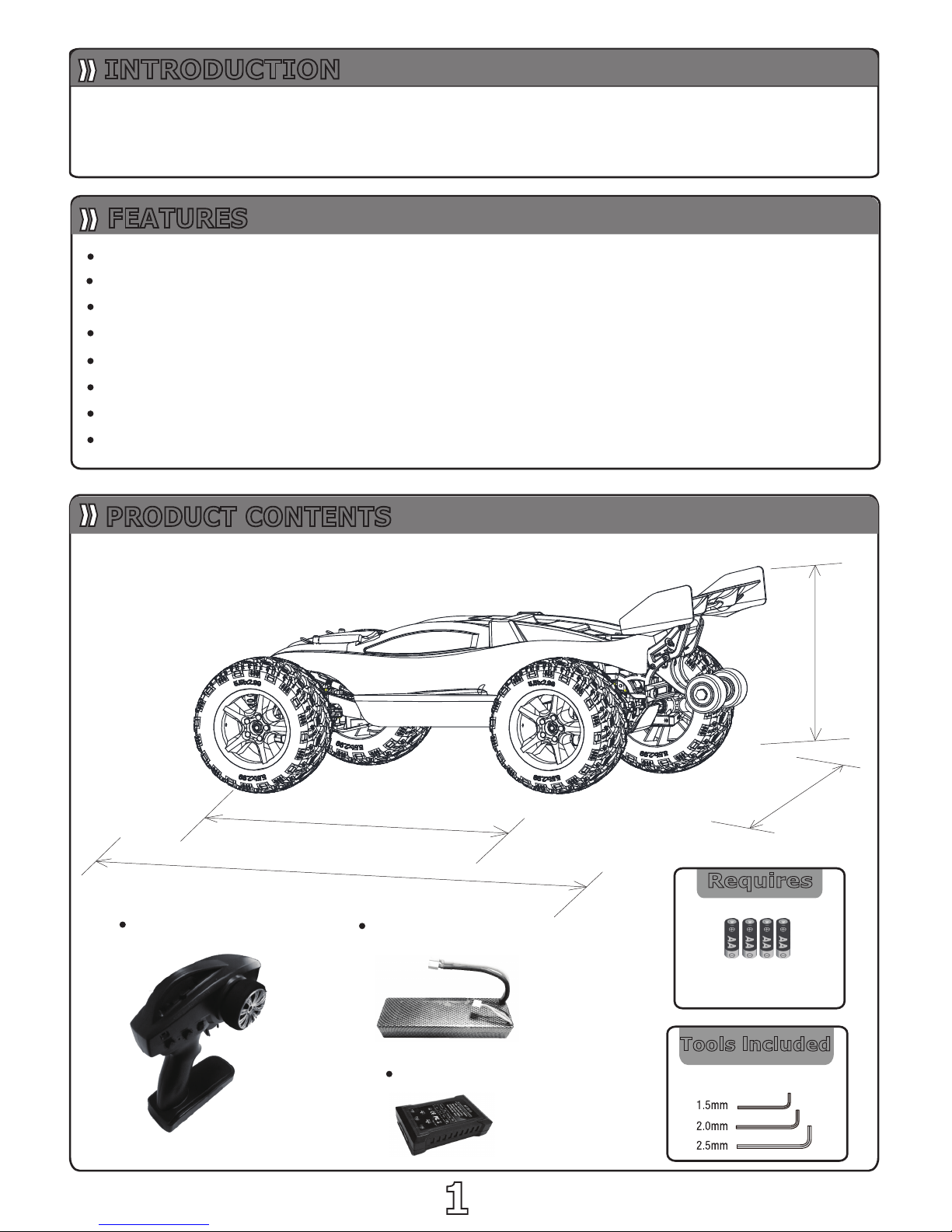
Bright LED
Adjustable wheel bar set
All bearing throughout
Adjustable rear wing
Sealed,tunable limited-slip differentials
All terrain tires & agreessive electroplate wheel
Oil-filled ultra AL shocks with progressive dual-springs
Fully assembled and Ready-To-Race
Thank you for purchasing this VKAR racing model.This manual contains
instructions on operating and maintaining the Bison .Please take a monent
to read through this manual to familiarze yourself with this model.
Tools lncluded
Requires
11
INTRODUCTION
532mm
380mm
218mm
330mm
Charger
Transmitter
Hex Key
4 PCS AAA Batteries
(For Transmitter)
Scale:1/10
Drive System:4WD
Power Battery
FEATURES
PRODUCT CONTENTS
22
IMPORTANT INFORMATION
The Bison is a powerful RC car that will bring much
enjoyment.Howewever,improper use can cause damage
and bodily injuries.Please read the following information
carefully to avoid casualties.
This model can be operated with Ni-MH or Lithium Polymer
batteries. Due to the battery’s high energy,density,please pay
attention to the following information to avoid injuries or
damages.
WARNING:
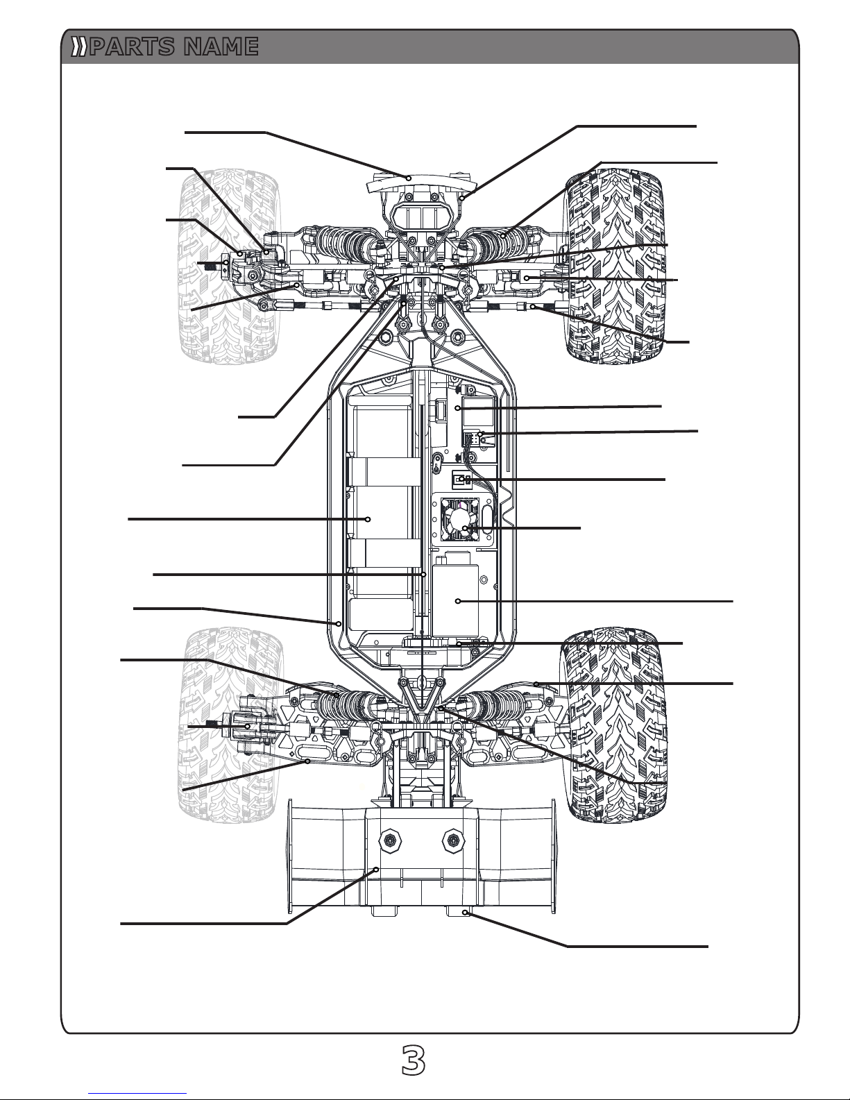
Front Bumper
Hub Carrier
Steer Block
Wheel Hex Hub
Body Mount Bracket
Chassis
Battery
Rear Hub Carriers
WING
Motor
Electronic Speed Control
Receiver
Turnbuckle
(toe Link)
Tailwheel
Shock
Front Shock Stay
Suspension Arm
Shock
Rear Shock Stay
Motor Mount
33
Support Bracket
Power Switch
Steering Servo
Turnbuckle
(Camber Link)
LED Light
Fender
Suspension Arm
Center Shaft
PARTS NAME
44
RADIO CONTROL INSTRUCTION
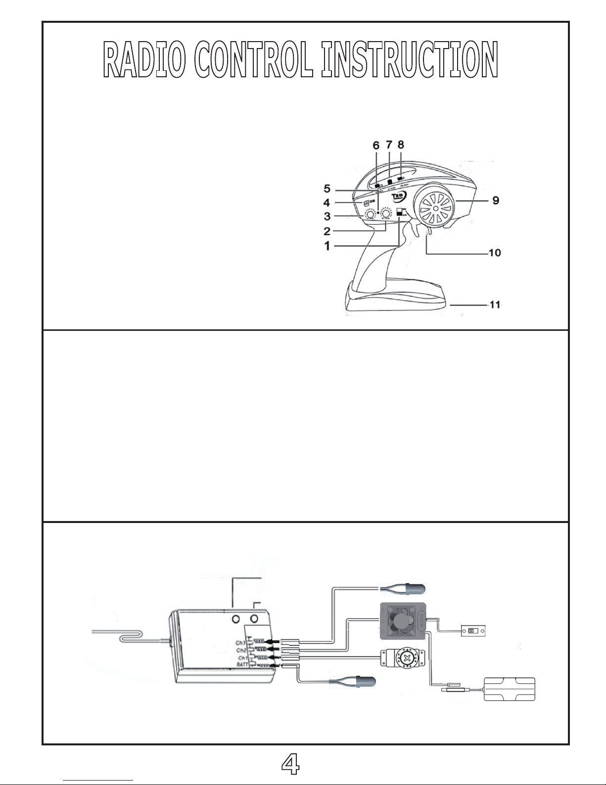
2.4G RC with 2-channels setup and fail safe function
1.Power Switch
2.Throttle Trim
3.Steering trim
4.Power /Ted Indlcator
5.Bind Key F/S Set
6.Steering Reverse
7.Steering D/R
8. Throttle Reverse
9.Steering Control Wheel
10.Throttle Trigger
11.Battery Box
Blnd Match
1. Turn on the receiver power,Press the bind key,the receiver’s Led should
be flashing.
2.Turn on the transmitter.
3. When the led on the receiver becomes solid,the binding process is completed.
Fail safe function
Normally the channels should be improperly presetted which simulates thefailure
being foundon them.Press the Bind key on the transmitter twice and LED should
flash thrice thrice likewise.All the way down,fail safe function is activated.
The system returns to normal situation if no custcomed setting is performed.
Generally Receiver System
LED Light
ESC
Servo
Battery Box
Receiver Switch
LED Light
Receiver Aerial
Bind Key
Bind Indicator
Red wire “A”
Blue wire “B”
Black wire “C”
Servo
Receiver
Power
Switch
Set Key
ESC
Model
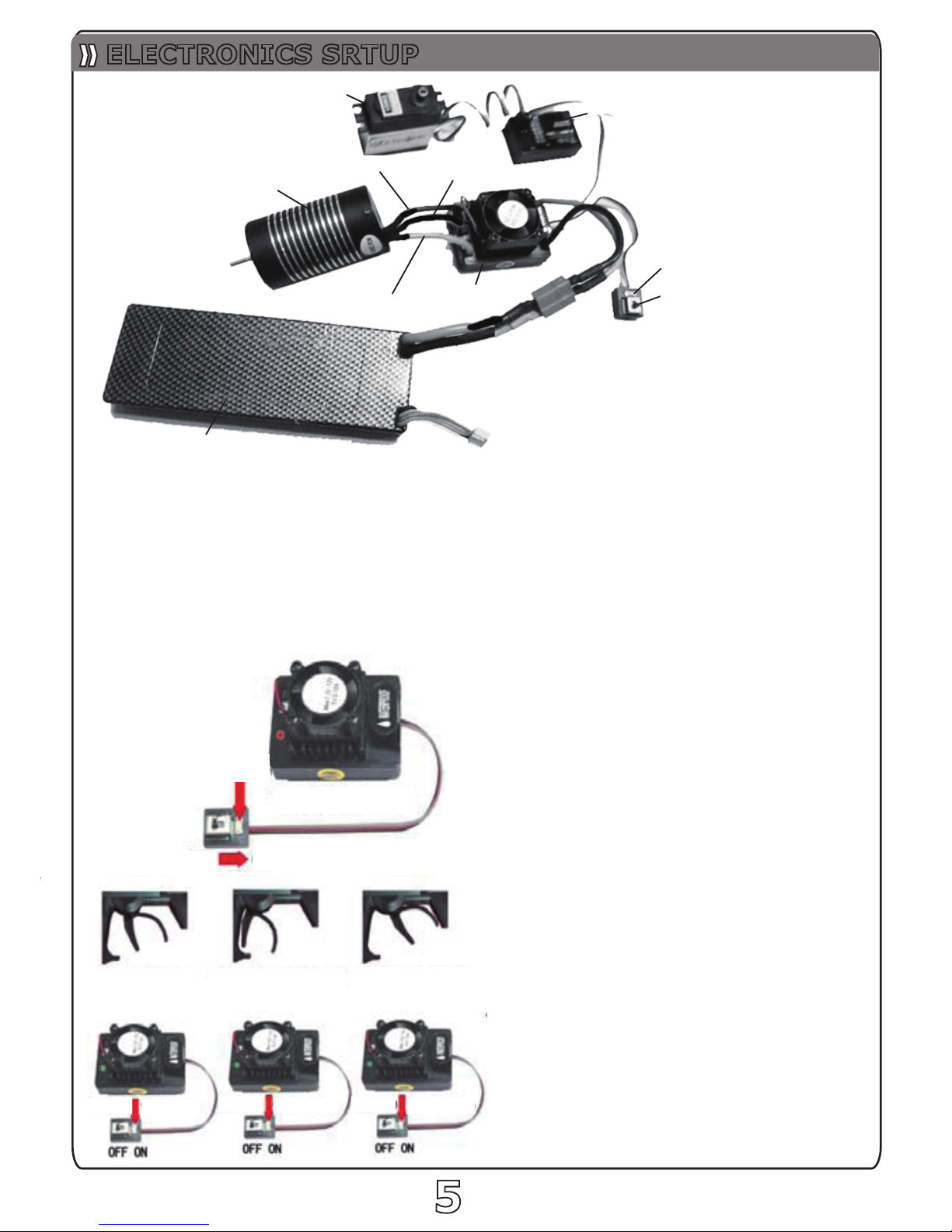
ELECTRONICS SRTUP
Hold the SET button
Red flashing, loosening
Neutral point Top polint of tjll throttle Top polint of tjll broke
Green LED
flashes once
Green LED
flashes twice
Green LED
flaches thrice
55
Begin to use the new ESC
1.Connect the ESC,motor,receiver,battery
and servo according to the following diagram
The #A,#B,#C wires of the ESC can be connected
with the motor wires freely.If the motor runs in the
opposite direction,please swap any two wire
connections.
Note:You can use the transmitter to set the throttle
channel to the “Reverse”direction,and then the
motor will run oppositely.Please calibrate the
throttle range again after changing the direction of
throttle channel.
2.Throttle Range Setting(Throttle Range Calibration)
In order to make the ESC match the throttle range,you must calibrate it when you begin to use a new ESC,
or anew transmitter,or after changing the setting of the neutral position of throttle channel.ATV or EPA
parameters,otherwise the ESC cannot work properly.
1).Switch off the ESC, turn on the transmitter, set the
direction of throttle channel to “REV”,set the
“EPA/ATV” value of throttle channel to “100%”,and
disable the “ABS” brake function of your
transmitter.(Note1)
2).Hold the “SET”key and then switch on the ESC,
when the red LED begins to flash,release the key
immediately.
(Please check the picture on the right side)
3). Set the THREE points according to the
steps shown in the picture on the right side.
a)Neutral point
b)End point of forward direction
c)End point of backward direction
4). When the process of calibration is finished,
the motor can be started after 3 seconds.
Note1: If you don’t release the “SET”key
after the red LED begins to flash,the ESC
will enter the program mode,in such a case,
please switch off the ESC and re-calibrate the
throttle range again from step 1 to step 4.

Steering angle
is more
66
Steering angle
is less
2. Charging the Battery
3. Loading the Battery
1. Wing Assembly
Quidck Start Guide
RADIO SYSTEM SETUP

7
47
46
45
48
50
52
51
55
54
52
50
51
49
49
57
56
57
46
47
M2.5x8
10x15x4mm
10x15x4mm
103
99
98
96
57
31
102
101
100
5x10x4mm
4mm
5x10x4mm
M3x3mm
M2.5x8mm
101
4mm
97
102
9
Differential Assembly
Front Driver Shaft Assembly
CORRECT
WRONG

8
107
108
109
98
31
103
108
107
110
101
98
104
105
106
98
97
96
47
3.5mm
M2.5x8
4.0mm
5x10x4mm
5x10x4mm
M3x3mm
15T
Rear Driver Shaft Assembly
TIPS:
The slipper clutch adjstment short cut
Use 1.5mm hex key,Insert the hold as the picture below.
Grasp the both sides of rear wheels,rotate in the same direction.
Adjusting the Slipper clutch
NOTE: the slipper clutch adjustment too loose or tight
may result in damsge the gear during racing.

M3x15
160
109
9
156
157
160
159
158
41
41
31
161
4
4
33
4
118
69
101
60
4
41
41
102
124
123
121
132
120
122
124
121
119
33
117
115
116
5x8x2.5mm
5x8x2.5mm
5x8x2.5mm
5x8x2.5mm
121
69
4.0mm
M3x20mm
M3x20mm
M3.0mm
M3.0mm
M3x10mm
M3x10mm
M3.0mm
M3.0mm
M3x8mm
Steering Assembly
Motor Mount Assembly
NOTE: Rotating the nut 115 to seek
suitable degree of tightness.
NOTE: Rotating the nut 115 to seek
suitable degree of tightness.
NOTE: Look out the interval between motor gear 161
and spur gear 109 if the screw is loosened 160 please adjust it.

1.Fill shock body with 4/5 silicone fluid(purchase seperately),pump the shock shaft
up and down to remove any air bubbles.
2.Wait the air bubbles pumped out,then pull down the shock shaft to the bottom,fill
the silicone fluid up to 2 mm,after that ,tighten the shock head 1.
3.Install the spring,shock assembling finished.
Shock Aaaembling Steps:
FRONT
REAR
10
12
13
22
23
7
7
12
1
3
2
16
11
9
10
10
3
11
15
24
19
18
5
9
43
13
61
61
44
28
43
13
41
28
41
Shock Assembly
Suspension Arms Assembly
NOTE:
Pay attention to choose
the right hole when installing

ET1001
ET1002 ET1003
ET1004 ET1005 ET1006
ET1007
ET1008
ET1011
Front
Rear
Front
Rear
ET1012
ET1013
ET1014 ET1015 ET1016 ET1017 ET1018
ET1019
ET1020 ET1021 ET1022 ET1023 ET1024
ET1025
ET1041
ET1029
ET1030
ET1031
ET1033 ET1034 ET1035 ET1036
ET1037
ET1038
ET1039 ET1040
x6
x2
x1
x1
x2
x1
x3
x4
x8
M3x10
M3x16
x2
x2
x1
Front
x2 x2
ET1028
x1
x4
1111
SPARE PARTS
ES1022
ET1010
x1
x1
x1
x1
x2
x4
M3x8
x1
x1
ET1026 ET1027
x2
ET1032
x4
x1
x1
x2
x2
x4
x1
x1
x4
Rear
x1
x2
x2
x2
x2
x2
x2
x2
x2
x2
x2
6.8mm
6.8mm
5.8mm
x2
x1
x1
M4X8
Left
Right
Right
Left
Front Rear
Left
Right
x2
x1
x1
x1
x1
x1
x1
x2
x1
x1
x2
x2
x2
x2
x2
x2
x2
M4x8
M3x6
M3x8
M3x10
M3x8
M3x15
x1
x1
x1
x2
x2
x2
x2
x2
x2
x2
x2
x2
x2
x2
x1
x2 x4
x1
x1
x4
x2
x2
x2
3x46mm
3x40mm
Front
Rear
x2
x2
x2x2
ET1042
x1
x1
M5
M5X85
x2
x2
M3x16
x2
x2
M4x15
x1

ES1001
ES1002
ES1003
ET1043
ET1044
ET1045
ET1046
ET1047
1212
SPARE PARTS
MA309
MA310
MA311
MA316
MA319 MA320
MA321
MA328
MA330
MA331
MA336
MA337
MA348
MA349
MA350
MA354-B
MA355
MA357 MA358
MA361
MA362
x2
x4
x1
x1
x1
x1
x1
x1
x10
x2
x1
x2
x1
x1
x1
x1
x1
x2
x1
x1
x1
x2
x1
x1
x1
x1
x2
x1
x1
x1
x2
x1
x1
x1
x1
x1
x4
x4
x2 x2
x1
M3x16 M4x15
x4x2
x2
x2
x2
x2
x2
x1
Front
x2
x2
x2
x2
x1
Rear
ET1049
ET1048
M4x12
M3x16
M3x16
M3x8
M3x8
ET1052
x2
x2
x2
ET1050
ET1051
x1
x1
x1
2x16.8
M5
ES1040
x2
x2
ES1046
x2
x1
x1
SPARE PARTS
x1
x4
x2
x2
Front
Rear
x1 x1
x2
x1
x1
x1

ES1073-B
MA601
ES1073-A
SPARE PARTS
1313
SPARE PARTS
OPTIONAL PARTS
SW101
SW104
SW201 SW202
SW206
x10
x10
IM3x3
x10
KM2.5x8
x10
x10 x10
x10
x10
EC102
OR101
EC101
x10
M5 NYLON
M3 NYLON
x10
2.5mm
4.0mm
x10
OR102
x10
OR104
x10
OR107
x10
ID 3.0x2.0mm
ID 4.5x1.5mm
ID 21.5x0.8mm
SPARE PARTS
NT103
NT102
x10
M3 NYLON
M3 FLANGED
x10
NT105
x10
x10
x10
x10
KM4x8
SW303 SW306
PM3x10
SW308
SW310
SW311
PM3x8
x10
SW312
PM3x23
SW313
x10
SW309
SM3x15
1.5x7.8mm
PN104
x10
2.0x16.8mm
5x8x2.5
5x10x4
10x15x4
8x12x3.5
x10
ID 2.5x7x0.2mm
ID 5x7x0.2mm
ID 5x12x0.3mm
SH101
SH102
SH103
x10
NT101
PN101
x10
ID 16x1mm
PM3x6
IM4x20
自攻SM3x10PM3x16 PM3x20
BB104
BB103
BB102
BB101
x10 x10x4x4
x4x4
ELECTRONIC COMPONENTS
x1
x1
x1
x10
SW314
PM4x15 PM4x12
ET1053 ET1054
ET1055
ET1056
ET1057
MA704
ET1058
60A
3660
2500KV
9KG
100A
x1
x1
x1
x1
x1
x1
x1

1414
1515
EXPLOED VIEW

1616
Nu mb er Na me
Sp ec if ic at io n
Do sa ge Nu mb er Na me Spe ci fi ca ti on Do sa ge Nu mb er Na me S pe ci fi ca ti on Dos ag e
1 Hydraulic top button 1 4 58 Lower Deck-F 1 115 Saver Spring 1
2
Hydraulic ball head c overed
4 4 59 Box Post 4 116 Saver Spring 1
3 Universal _Ball 5.8 14 60 Screw M3x10 18 117 Servo Saver-B 1
4 Nylon Nut M3 8 61 Front Suspensio n Arm 2 1 18 Servo Saver-A 1
5 Shock_picston 4 62 Rear Suspensio n Arm 2 119 Steering Arm 1
6 Shock_bo dy-F 2 63 PIN 3X40 4 120 Steer Post-R 1
7 E-Clip 2.5 8 64 Steer Holder L 1 1 21 Bearing 5X8X2 .5 4
8 Shock Shaft 2 65 Steer Blo ck L 1 1 22 Ste
er Link 1
9 O-ring3x2 10 66 Steer Block R 1 1 23 Steer Po st-R 1
10 Shock_Support 8 67 Steer Holder R 1 1 24 Sleeve 4.5 2
11 Shock_Cap 4 68 Kinpin Case 4 125 Bumper F 2
12 Shock Ring 4 69 Screw M3x20 6 126 Screw M4x20 2
13 O- Ring 16x1 4 70 Screw M4x12 4 12 7 Support Bracket F 2
14 Dust Cover 4 71 Push-pull Rod 2 1 28 Fender L 1
15 Slingshot stop 4 72 Ball Cup 24 4 1 29 Fender R 1
16
Hydraulic ball head buckle
4 73 Screw M3x15 2 130 Antenna Mo unt 1
17 6.8 Ball Screw B 2 74 Washer
3x6x2 4 131 Tube 1
18 Shock_Spring-S 4 75 CVD shaft 1 132 Main Chassis 1
19 Shock_Plastic Parts 4 76 PIN 2X12 1 133 Iron Center Shaft 1
20 Shock Spring-F 2 77 PIN 2X16.8 1 134 Gear Cover 1
21 Air Vessel 4 78 PIN 3X12.7 1 135 Bumper 1
22 Shock_Body-R 2 79 CVD Holder 1 136 Bumper 1
23 Shock Shaft 2 80 Fixed pin 1 13 7 Holder_L 1
24 Shock Spring-R 2 81 CVD Ring 1 138 Holder_R 1
25 Bumper 1 82 Wheel Hub 1 139 Ho lder 1
26 Bumper 1 83 Screw M3x1 6 16 14 0 Fixed dam 1
27 Bumper 1 84 Push-pull Rod 50 2 141
Wing
1
28 S
crew M4X8 6 85 Rear Hub Carriers 2 142 Pressure_pad 2
29 Screw M3X8 26 86 Shock Stay-F 1 143 Screw M4x15 2
30 Screw M3X6 12 87 Nut M3 4 144 Rally_tyes 4
31 Screw M3x3 1 1 88 Washer 4 145 Tire Inner 4
32 Pressure_pad 4 8 9 Nut M3 8 146 Wheel 4
33 6.8 Ball Screw_C 2 90 Screw M3x23 4 14 7 Nut M5 M5 5
34 Front Anti-roll Bar 1 91 Ball Cup 34 8 1 48 6.8 Ball Screw_B 8
35 4.8_Ball-Sleeve 4 92 Body Mo unt Bracket-F 1 149 Magic Tape 2
36 Ball Cup 26 4 93 Spring Lock 4 150 LI-PO Battery 1
37
Rear Anti-roll Bar 1 94 Shock Stay-R 1 151 Sponge Block 1
38 Bulkhead 4 95 Body Mount Bracket R 1 152 Mantle 1
39 Gear Box 2 96 Differential gear 15T 2 153 Servfo Stay 2
40 Gear Box 2 97 Spacer 2 154 SERVO 9KG 1
41 Screw M3X10 28 98 Bearing 5X10X4 5 155 Servo_ Arm 1
42 Arm Holder 4 99 Sponge Block 1 156 Motor 366 0 2500 KV 1
43 Pin Cap 8 100 Drive Shaft-F 1 157 Motor Mount-B 1
44 Pin 3x46 4 101 E-Clip 4 4 158 Mo tor Mo unt-A 1
45 Differential Ho using 2 102 Bearing bush 1 159 Screw
Spring 1
46 Bearing 10X15X4 12 103 Drive cup 2 160 Screw M5X85 1
47 CVD Holder 1 104 Slipper Screw 1 161 Motor Gear 1
48 O_Ring 21.5x0.8 2 105 Saver Spring 1 162 Receiver 1
49 O_Ring 4.5x1.5 4 106 Pre Ring 1 163 ESC 60A 1
50 Spacer 5X12X0.3 4 107 Driver Disc 2 164 Post 2
51 PIN 1.5X7.8 4 1 08 Slipper Sheet 2 165 Painted Body 1
52 Differential gear 24T 4 10 9 Spur Gear 52T 1 16 6 LED 1
53 Spacer 2.5x7x0.2 8 110 Driver Shaft-R 1 1 67 Tail Wheel Holder 2
54 Differential gear 11T 8 111 Push-pull Rod 2 168 T
ail Wheel 2
55 Differential pin 4 1 12 Lower Deck-R 1 169 Tail Wheel Holder 1
56 Drive the cone gear 43T 2 113 Servo Rod 1
57 Screw M2.5x8 1 0 114 Ball Cup 16 2
Bill Of Material
 Loading...