


ViZion DR + Straight Arm Installation Guide v2.0
Opal UAI 2.3.x.x
1
Customer Support
1.800.366.5343 – support@viztek.net
VZDR-UG-ViZion DR + Straight Arm Installation Guide-D-16082013.2.0
VIZION DR +
Straight Arm
Installation GUIDE
ViZion DR + Straight Arm Installation Guide v2.0
Opal UAI 2.3.x.x
2
Customer Support
1.800.366.5343 – support@viztek.net
VZDR-UG-ViZion DR + Straight Arm Installation Guide-D-16082013.2.0
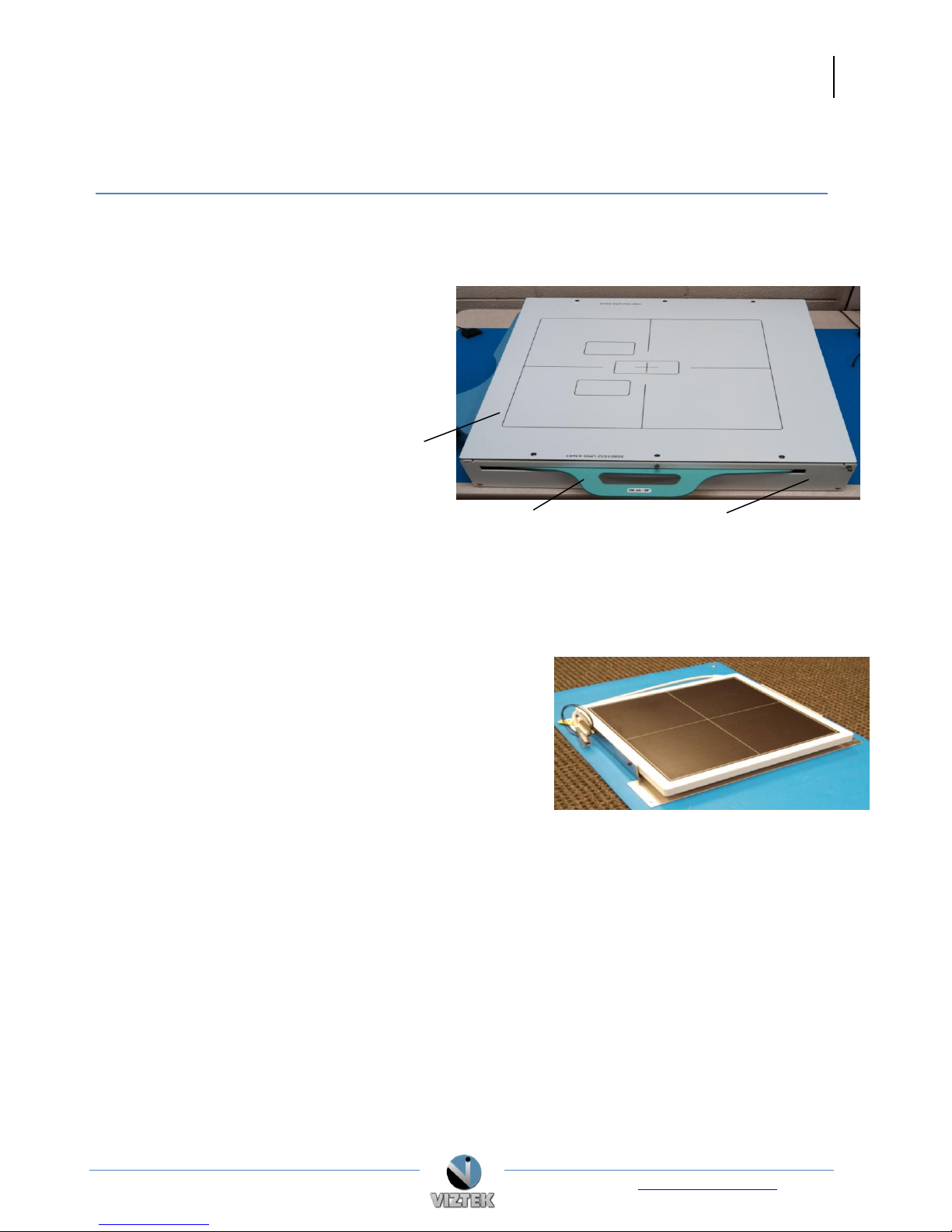
Grid Holder
Bucky Front Plate
Bucky Cover
Figure 1
Figure 2
ViZion DR + Straight Arm Installation
This guide will provide you with detailed instructions on how to assemble and mount the ViZion DR +
within the Viztek Straight Arm.
1. Remove the following: Figure 1
a. Grid holder
b. Bucky cover
c. Bucky front plate
2. Remove the 12 screws fastened to the bottom of the bucky cover.
3. Remove the 4 screws that hold the AEC/grid guide to the bucky.
4. Attach ViZion DR+ to the mounting plate, using 2 screws on each side. Figure 2
NOTE: Install a grounding strap to the ViZion DR+
detector in the screw hole labeled with the
universal grounding symbol.
5. Place the ViZion DR + dector and the mounting plate
onto the bucky
6. Align the plate with the same screw holes used for the
AEC/grid guide which were removed in step 3.
7. Place the AEC/grid guide on top of the panel and fasten 4 machine screws from the bottom.
8. Plug the correct cables to the ViZion DR+ detector plate and the AEC/grid.
9. Mount bottom plate attaching the grounding strap from ViZion DR + detector to the universal
ground located on the bottom cover.

ViZion DR + Straight Arm Installation Guide v2.0
Opal UAI 2.3.x.x
3
Customer Support
1.800.366.5343 – support@viztek.net
VZDR-UG-ViZion DR + Straight Arm Installation Guide-D-16082013.2.0
Figure 3
10. Install the front plate. Figure 3
11. Calibrate the generator (refer to the Viztek Website Resource
page for more instructions if needed )
12. Calibrate the panel (refer to the Viztek Website Resource page
for more instructions if needed)
13. Once generator and panel have been calibrated complete the following:
a. Install top cover
b. Slide grid into place
c. Calibrate AEC
14. Capture test shots.
 Loading...