

Page 1
Visit us on the Web:
www.vizitechusa.com
Mailing Address:
ViziTech USA
103 East Sumter Street.
Eatonton, Georgia 31024
Call Us:
706-749-8099
404-725-5104 cell
Thank you for your purchase!
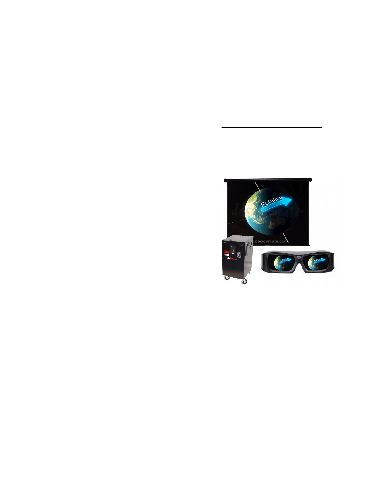
3DAVRover
User’s Guide 2014
706-749-8099
www.vizitechusa.com
ViziTech USA
Page 2

WARRANTY AND MAINTENANCE INFORMATION
Thank you for purchasing the AVRover portable AV system from Sound Video
Systems. We have assembled this system according to strict quality standards.
You should receive many years of reliable service from your AVRover. Your
AVRover may contain components with manufacturer’s warranties that pass
through to you. Sound Video Systems warrants each AVRover “Base Unit” for
a period of five (5) years from the time of end user delivery. The “Base Unit”
includes the powder coated metal cart, drawers and/or storage compartments,
wheels, wiring harnesses, mounted speakers and the AVRover brand mixer
amp. Components such as projectors, DVD’s, Computers, and other devices
will carry their own manufacturers warranties that will be passed on to you.
You will receive operation manuals, remotes and batteries for the major component parts in your AVRover system. Even though you may not need these
items to operate your system, you should keep them in a safe place for future
use.
The rack screws used in the installation of your AVRover may require a security
bit to remove the components for maintenance. The keys to the storage compartment are attached to the outside of the system. Keep this key in a safe
place.
STANDARD WARRANTY- The AVRover System comes with a five (5) year
Limited Warranty.
All component parts of the AVRover carry various warranties from the manufacturers of the particular component part. Sound Video Systems is a factory authorized warranty repair facility for most of the component parts contained in the
system. If you should experience trouble with your system, call us toll free at
(800)724-0236. We will assist you in getting your system functioning as quickly
and efficiently as possible.
The five (5) year limited warranty includes parts and telephone assistance, excluding damages caused by accidents, misuse, lightning, fire, other acts of God,
etc. This warranty does not include transportation of the AVRover to or from a
designated repair facility. The customer is responsible for providing technically
capable personnel to affect preventative maintenance, and if necessary, simple
repairs under the direction of SVS technical staff including but not limited to the
removal of a faulty component part for replacement. Sound Video Systems will
have the option to replace or repair any AVRover “Base Unit” parts under this
warranty.
NON-WARRANTY SERVICE
Please be aware of the following. Some of the equipment integrated into the
AVRover system may still have a separate manufacturer’s warranty. If a com-
ponent of your system fails, you will be responsible for disconnecting it from
your AVRover, sending it to Sound Video Systems or another Warranty Repair
Facility, and reintegrating it back into your AVRover. Repairs, if not covered by
a manufacturer’s warranty will be billed at standard repair rates. Phone support
will be available from AVRover certified technicians.
Available Content for the 3DAVRover
Reference
#
DESCRIPTION
SVS-E3D5
Eureka.in 3D Stereoscopic Content by Designmate (200 videos,
Purchase) 5 yr single user license
SVSE3DHD
Eureka.in 3D Stereoscopic Content by Designmate Hard Disc for
end user installation only
SVS-E3D1
Eureka.in 3D Stereoscopic Content by Designmate (200 videos,
1 yr. license)
SVS-EA5
Eureka.in 3D Stereoscopic Animations by Designmate (50 ani-
mations 5 yr. license)
SVS-EA1
Eureka.in 3D Stereoscopic Animations by Designmate (50 ani-
mations 1 yr. license)
SVS-AIB
Amazing Interactives Biology Lessons (Purchase)
SVS-AIC
Amazing Interactives Chemistry Lessons (Purchase)
SVS-AIM
Amazing Interactives Math Lessons (Purchase) 33 lessons
SVS-AIE
Amazing Interactives Elementary (Purchase) 8 Individual Learn-
ing Modules
SVSAIDTS Amazing Interactives Discover the Senses (Purchase)
SVSAIDTR
Amazing Interactives Discover the Respiratory System
(Purchase)
SVS-CS3D
Cyber Science 3D Stereoscopic Interactive Content (75 files,
Purchase)
SVS-CS3D
Cyber Science 3D Stereoscopic Interactive Content (75 files,
Purchase)
SVS-JTMP JTM Concepts Science Primary Content (31 lessons)
SVS-JTMI JTM Concepts Science Intermediate Content (53 lessons)
SVSJTMJHS JTM Concepts Science Jr. HS Content (52 lessons)
SVSJTMSHS JTM Concepts Science Sr. HS Content (47 lessons)
SVSVfrogD V-Frog Dissector (single user license)
SVSVfrogDS V-Frog Dissector (site license)
SVS3DWARRA
NTY
AVRover 3D Content Support 1 yr Extended Warranty
Page 3
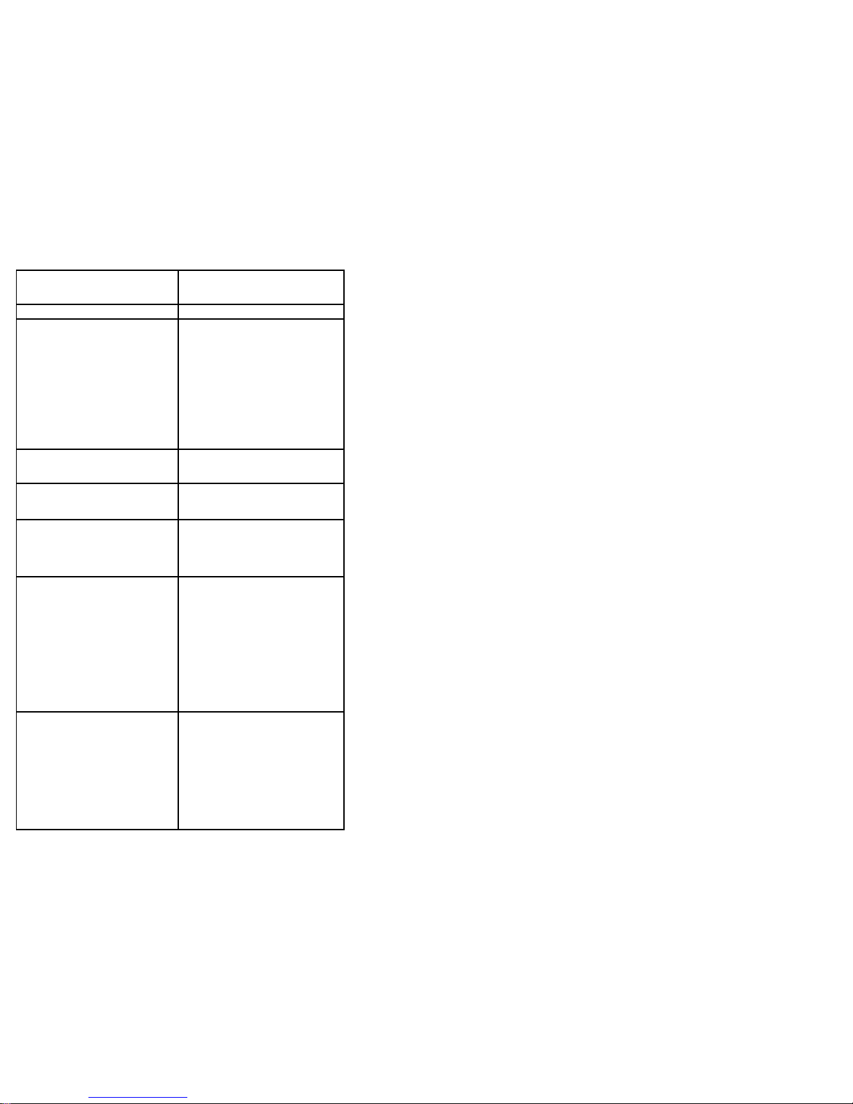
Table of Contents
Important Information…………………...........
Components of the AVRover ………….……..
Getting Started…………………………….......
Using the AVRover…………………………......
Powering up the AVRover …………….
Adjusting the Projected Image………….......
Removing the Projector..............................
Using the Computer………….......
Amplifier……………………………….......
Microphone…………………………...........
Turning Off the System ……………………...
Troubleshooting….………………….................
Troubleshooting Cont’d……………………….
10
________________________________________________________
Troubleshooting Cont.
Problem Check
Picture is green on INPUT 1
(COMPONENT)/INPUT 2
(COMPONENT).
Picture is pink (no green) on INPUT 1 (RGB)/INPUT 2 (RGB)
Change the input signal type
setting
When you cannot select an input
signal type, select “Color is faded or poor” in Help menu, after
selecting an item other than
“RGB” in Picture Mode” , and
then select an input signal type.
Picture is too bright and whitish.
Image adjustments are
incorrectly set
The cooling fan becomes noisy.
When temperature inside the
projector increases, the cooling
fan runs faster.
The lamp does not light up even
after the projector turns on.
The lamp suddenly turns off during
projection.
The lamp indicator is illuminat-
ing in red. Replace the lamp.
The image sometimes flickers.
Cables incorrectly connected to
the projector or the connected
equipment works improperly.
Select “Vertical stripes or flick-
ering image appear” in the
“Help” menu and make the
necessary adjustments.
If this happens frequently, re-
place the lamp.
The lamp needs a lot of time to turn
on.
The lamp will eventually need to
be changed. While the remaining lamp life draws to a close,
replace the lamp.
12
2
3
4
4
4
5
6
6
8
8
9
Page 4
Important Information
With proper care, Sound Video Systems’ presentation console
will provide you with many years of trouble-free operation.
The projector inside the console is a high-brightness light source. Do
not stare directly into the light and do not allow children to look directly into the light.
To reduce the risk of fire or electric shock, do not expose this product
to rain or moisture. Do not expose the console to dripping or splashing liquids.
Do not place any object that has an open flame or is filled with liquid
on the console. Avoid keeping beverages on top of the console.
This console has a three-wire grounding-type plug. This plug only fits
into a grounded power outlet or extension cord. Do not remove third
prong or try to fit into a standard outlet. Contact an electrician to
replace outlet if needed.
To prevent tripping hazards and damage to cables, coil any extension
cable that exits the console onto the cable wrap, especially during storage or transport.
Do not plug unnecessary item in auxiliary power outlet. The outlet is
intended for laptop and document camera only. The system and the
additional load may overload the system power surge.
Use caution when attempting to open the rear door of the AV Rover,
as wires are attaching the unit to the rear door. Removing the rear
door without attention to the attached speaker and amplifier wires
will damage the system.
Unit should be moved by authorized adults only; do not allow chil-
dren to move the unit. Do not sit or ride on unit.
Prior to moving unit, remove all equipment and items from on top of
unit and disconnect all electrical cords from wall outlets.
Do not allow equipment to overhang or extend beyond edge of top or
shelves and close all doors and drawers, removing the keys before
moving.
Unlock the casters. PUSH unit, from narrow side only, NEVER
PULL.
Be certain you have clear vision and avoid rough or uneven surfaces
and remove obstacles in your path.
Push at a slow walking pace, applying force to the narrow side.
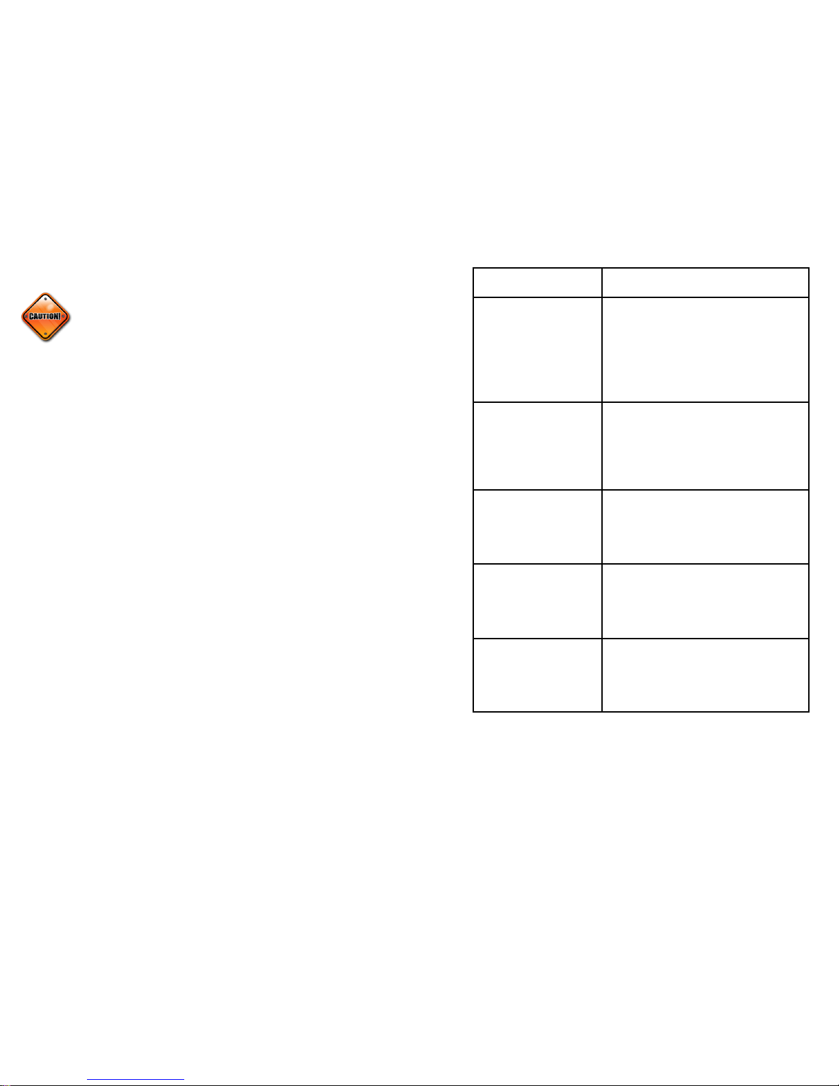
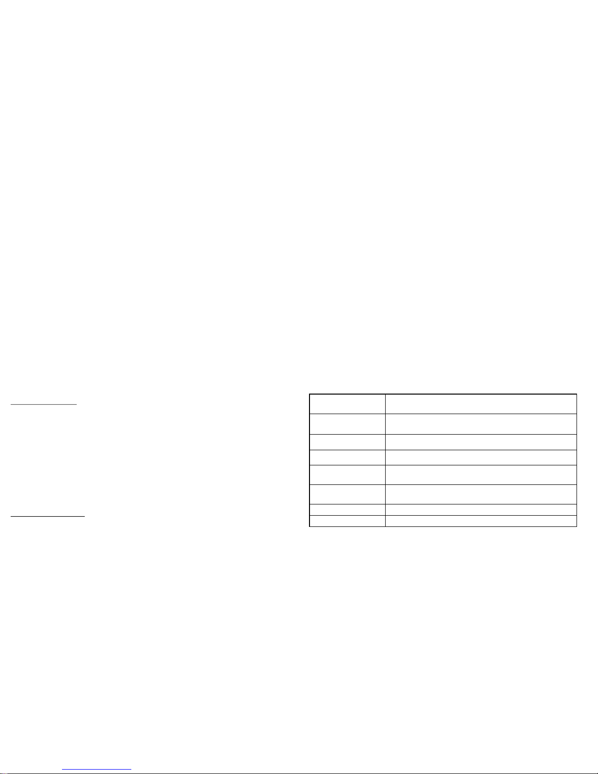
Troubleshooting
Problem Check
No picture and no sound or
projector does not start.
System power cord is not plugged into the wall
outlet.
Power to the external connected devices is off.
The selected input mode is wrong.
Cables may have come loose.
External output has not been set on the laptop
computer.
Sound is heard but no picture appears or picture is
dark.
Cables may have come loose.
“Bright” is set to the minimum position.
Depending on the computer you are using, an
image may not be projected unless the signal
output setting of the computer is switched to the
external output. Refer to the computer’s opera-
tion manual for how to switch its signal output
settings.
Color is faded or poor.
Image adjustments are incorrectly set on the
projector.
Make adjustments of “Color” and “Tint” in
“Picture Mode” (Video Input only)
Video Input system is incorrectly set on the
projector.
Picture is blurred; noise
appears.
Adjust the focus
The projection distance exceeds the focus range.
(Computer Input Only)
Perform “Fine Sync” Adjustments (Phase Ad-
justments)
Noise may appear depending on the computer.
Picture appears but no
sound is heard.
Cables are incorrectly connected
Volume is set to minimum.
The amplifier is not turned on.
11 2
Warnings:
Page 5
Unplug the console during electrical storms or if it won’t be used for a long
period of time.
Unplug the console from the wall before you install any additional compo-
nents or perform any maintenance. In addition, make sure your peripheral
devices aren’t on when you’re making cable connections.
If you need to lift the unit for travel purposes, lift from the bottom, using
your legs to avoid personal injury or damage to the unit.
Find additional Safety information at www.avrover.com,
or call 800-724-0236
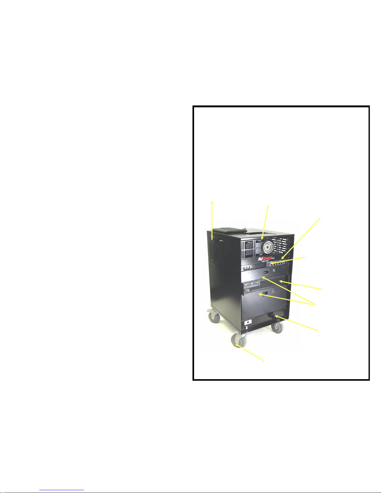
Components of the 3D Rover
Projector
XLR Input
Mixer /Amplifier
Computer
Projector
Adjustment
Retractable
25 ft power
cord
Non marking
locking wheels
Using the Computer:
1. Power up the projector as described in the above procedure.
2. Turn on the Computer by pressing the Power Button.
Turning off the System
1. Shut down the computer as you normally would power down
a computer.
2. Press the power button twice to turn off the projector. The
projector will ‘rev’ up its fan and then shutdown completely.
This may take a few moments, but be sure the projector does
shut down.
3. DO NOT unplug the system’s power cord until the projector
fan has stopped. Moving the system while the projector is still
hot may cause damage to the lamp.
4. Press the power buttons on the DVD/VHS and amplifier to
completely shut down the unit.
3 10
Locking Storage
Drawers
Page 6
Getting Started
Sound Video System’s
presentation console is
a rugged rolling unit (35” high) with all of its components securely mounted
inside. Using the presentation console is as easy as rolling it into place,
plugging it into an electrical outlet, and turning it on. There are no doors to
open, no shelves to deploy, and no need to find the remote
controls since all component controls are easily accessible, including the
projector that is securely mounted on an easily-adjusted, tilting shelf.
Using the Console
Because the cabinet is mobile, you can easily wheel it to any location for a
presentation. Once in place, you’re now able to access the devices to deliv-
er your multimedia presentation.
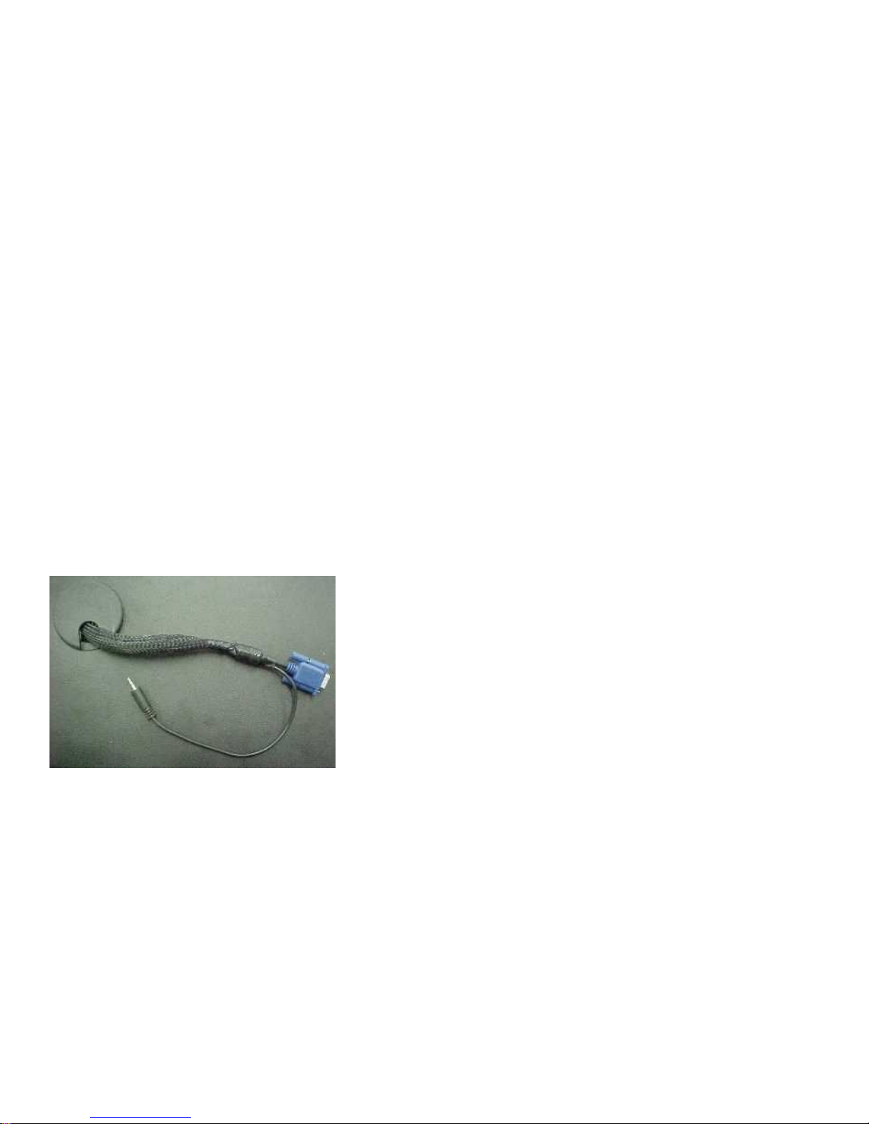
Connecting a User’s Laptop
The Sound Video System comes equipped with the cables needed to use a
laptop. Connect the VGA cable to the 15 pin monitor jack on your laptop
and the audio cable to the headphones jack.
Using a Laptop Computer
1. Connect the pull out VGA and audio cable and connect to the computer and power the projector and the PC as described above.
2. If the computer’s image is not already displaying on the projector,
press the “Video Input or Source” button. The projector should
now display the image of the connected computer.
3. The Laptop Cables will always be connected to VGA Input #1.
4
9
Page 7
Powering up the Sound Video System
1. – After plugging the unit into the electrical
outlet, turn on the projector. Press the power button shown through the
top of the console.
2. – The projector will display which video output it is
currently utilizing. To select the option you want to use, (eg. Computer,
VCR, DVD) press the “input” or “source” button until your desired video
source is showing.
Turn on the projector
Video Input
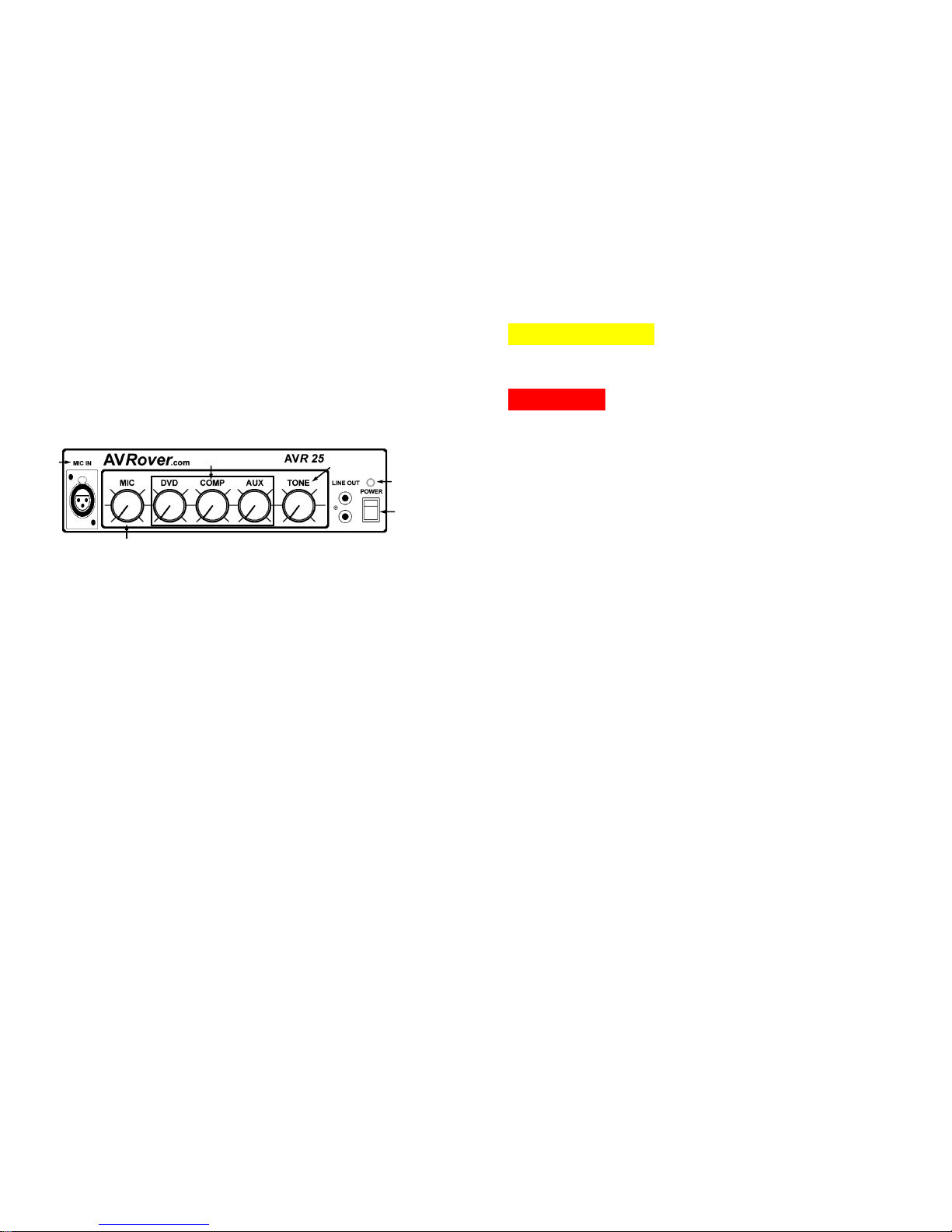
Using the Components
The Sound Video System comes equipped with an amplifier, line out, and
microphone input jack.
Amplifier
If the red LED is not already lit, located above the power button, press the
button to the “on” position. Once “on,” the red LED should light on the
amplifier.
Microphone
Connect the microphone to the input shown.
Some microphones have on/off switches on their handles. Verify that it is
turned on. The microphone will be ready to use as soon as it is plugged in.
The microphone has been programmed into the system to override any other audio output. Therefore, when you speak into the microphone, any other sounds that were playing will be lower in volume and the voice will be
heard through the speakers. Adjust the microphone volume control on the
amplifier.
Line Out
The red and white RCA jacks can connect external powered speakers to the
amplifier incorporating the AVRover into your existing sound system.
8 5
1
3
2
4
6
5
Page 8
6
Adjusting a Lopsided Image
If the image is lopsided, rotate one side of the console forward or back-
ward. If that doesn’t resolve the issue, you may need to adjust the keystone.
See projector manual for instructions.
Adjusting the Image
While you’re trying to center the rectangular image, please note that it is not
always possible to get a perfectly shaped image. This is because the screen,
projector, console, and floor are independent, physical variables.
When centering the image stand behind the console.
Using the adjustment pull cord on the side of the console, raise or lower
the image by pulling the cord. Lock it into place by pulling the cord
downward.
Moving the cabinet left or right will adjust the horizontal alignment.
To make the image larger, move the console backward, and likewise
move the console forward to make the image smaller.
The zoom lens will allow you to set the zoom to near maximum. This
will give you the largest image at the shortest distance, leaving a small
portion of the zoom to make final adjustments.
Projector & Combo Installation Instructions
Projector Removal
Remove projector mount by removing the projector face panel and the
projector mount assembly with the security bit provided. Note the adjustment cord configuration and undo from the cleat end. This will allow the
mount assembly to be removed. It may be necessary to disconnect the mi-
crophone cable from the amplifier to completely remove the shelf.
The projector is attached to the projector mount with machine screws
that can be removed with an Phillips head screwdriver. Note the position of
the spacers before removing the projector from the mount. Service can now
be performed on the projector.
Projector Installation
Use T-27 bit (located in accessory package) to remove 8 security screws
that secure back door. Gently remove door from unit (approximately 4 to 5
inches) and disconnect speaker wires from speaker located on rear door.
Feed rope into unit and clear from eyebolt on projection shelf. Leave
rope tied to D-ring.
Use T-20 to remove security plate and projector mount.
Set projector upside down with lens facing out and away from you.
Align lens in middle of mounting plate, or as close as possible.
Align mounting holes on bottom of projector with slots on mounting
plate.
If projector does not lay flat on mounting plate, use spacers to help level
projector.
Install projector mount assembly and security plate onto rack rails.
Laying system on its back side may facilitate mounting the shelf. Loop
rope through eye bolt, back through D-ring, and then out through console
and feed into cleat. Tie knot and make sure that projector has full range of
motion (up and down).
Attach yellow video cable (that is provided) to projector. Plug power cord
from projector and combo to power strip. Connect VGA cable to projector.
Slide cable jacket (provided) over the VGA cable and the laptop audio cable.
Make sure all cords and cables are reconnected before you put power to unit.
If you have any questions or concerns please call Sound Video Systems of
WNY, LLC at (800) 724-0236. Thank you for your business and
enjoy your AV Rover!
Additional 3DAVRover Options
7
SVS-CM2Max
Interactive Whiteboard System Option with
Freeclass and Wizteach Software
SVS-CM2MaxST
Short Throw Interactive Whiteboard System Option
with Freeclass and Wizteach Software
SVS-CM2MaxOS
Optional Hand Held Stylus for Onfinity CM2Max
SVS-ROVERPAD
Interactive Slate/Tablet
SVS-Lock
Wall Lock Bracket and AVRover Attachment Plates
SVS-DCS
Document Camera Shelf for Additional Work Sur-
face
SVS-PDC Protective Dust Cover (SVS200 or 3DAVRover)
SVS-3500
Projector Upgrade to 3500 lumens (Short Throw)
 Loading...