

Vizi-tec SBT-4K User Manual

www.vizi-tec.com
November 26, 2017
Vizible Technologies
SupaBrake
Third Brake Light Modulator 4K
(SBT-4K)
aka. SBT-4096
User Guide
Rev 1.1
Contact email@vizi-tec.com for more information
Page 1 of 24

Warranty & Specification, 3
Features & Functions, 4
Product Application, 5
Profile Selector, 6
Grace Period, 7
Frequency, 8
Modulation, 9
Slope, 10
Decay, 11
Appendix A (Time Segment vs. Grace Period), 12
Appendix B (Time Segment vs. Modulation), 13
Installation and switch access, 14 - 16
FAQ, 17 - 18
Cheat Sheet, 19
www.vizi-tec.com
November 26, 2017
Table of Contents
Contact email@vizi-tec.com for more information
Page 2 of 24

www.vizi-tec.com
November 26, 2017
WARRANTY & SPECIFICATION:
3 Year Limited Warranty!
We take pride in our products and stand 100% behind our design, workmanship and most importantly customer satisfaction. We
offer a full 3 year limited warranty with this product.
Firmware History:
10/12/17: [v1.0x] Ported over from v3.52 SB3 to new SBT hardware. SB3 engine designed to be access slide switches.
05/08/18: [v1.1x] Tweaked timing and minor bugs. Updated CANBus protocol.
Mechanical Dimensions:
Unit body:
Height = 8mm (0.315 inches)
Length = 24mm (0.945 inches)
Width = 35mm (1.378 inches)
Wire length:
175mm +/-10mm (7 inches +/-0.5) *Exclude connectors
Electrical Dimensions:
Wire gauge = 20 AWG.
Red = Input brake signal(+)
Black = Ground(-)
White = Modulated output
Input Voltage = 9.5VDC to 16VDC
Constant load current = 3.00 Amps @ 23C
Quiescent current = 700 uA
Operating Temperature = -30C to +50C
Storage Temperature = -40C to +95C
Fully compatible with all OEM light devices (bulbs or LEDs)
2 wire configuration with or without PWM technique
CANBus compliant
Page 3 of 24
Contact email@vizi-tec.com for more information

www.vizi-tec.com
November 26, 2017
FEATURES & FUNCTIONS:
Product Application:
The SBT-4K (Supabrake-Third Brake Light Modulator) is based on our popular, best in class, third generation SB3. The SBT-4K comes
packed with over 4 thousand profiles(4096 total) that are configurable on the fly through a 12 position toggle switch located on
device. Figure 1 shows the 12 selectable position toggle switch. From left to right are positions 1 thru 12.
The SBT-4K is specifically designed to work with any two-wire brake light devices - bulbs or LEDs. Such as those commonly found on
the rear window of cars and trucks; Also known as a third brake light or high mount brake light. Most third brake lights operate on a
simple two wire scheme and only active when the brakes are applied. They remain off at all other times. This results in a lack of
constant power to run the SBT’s time based algorithm. That is where the SBT comes in. It utilizes super capacitor technologies to
quickly store a tiny amount of power in a very short period of time, thus allowing its internal micro-controller to process the
algorithm.
Smart Algorithm:
(Standard)
(Usage = Automatic)
Upon applying the brake(s), the unit will send a burst of pulses to the vehicle's brake light(s). The duration of the burst is a function
of the time elapsed between the current braking cycle and the previous brake cycle. After this initial burst, this unit allows the brake
light(s) to function normally (solid brake light). (This algorithm is designed to eliminate target fixation as found in cheaper, passive
products that continuously "blink" the brake light(s) even though the vehicle is at a complete stop.) A time domain chart can be
viewed at the end of the document or at www.vizi-tec.com. The duration of the burst varies based on the profile selected. The
SupaBrake-Third Brake Light Modulator offers over 4096 different profile combination.
4096 Profiles:
(Standard)
(Usage = Manual)
User can select from over four thousand profiles on the fly via numerous slide switches. No need to remove or plug in a USB cable or
any external hardware to configure the kit. Full access to the algorithm is granted via the 12 slide switches. See page 5 to for switch
definitions and address.
Easy Plug and Play:
(Standard)
No need to cut, splice into the vehicle’s electrical harness. Simply unplug the stock connector that interfaces the third brake light
from the main harness. Plug the device in series. Done!
We have been manufacturing brake light modulators for over a decade and offer a wide selection for many popular motorcycles and
cars/trucks rear window third brake light. Chances are we have a plug and play kit for your vehicle. If you don’t see one listed
contact us at email@vizi-tec.com and we’ll work with you to make a custom kit at a discount.
Page 4 of 24
Contact email@vizi-tec.com for more information

www.vizi-tec.com
November 26, 2017
Grace Period:
(Standard)
(Usage = Automatic)
The SBT-4K will not modulate the brake light if the brakes are applied more than once within a certain time period. This is very useful
in heavy traffic so as not to annoy the person in the vehicle following behind. Its attribute can be set to 0 seconds, 3 seconds, 6
seconds or 12 seconds. Selecting 0 seconds defeats this function and allow the SBT-4K to modulate the brake light on each and every
brake application. See page 9 for more details.
Decaying Flash Routine:
(Standard)
(Usage = Automatic)
The burst of pulses is such that the period of the first pulse is slightly shorter than the following pulse and so on. This means that the
initial pulses will be faster whereas the later pulses towards the end of the burst will be slower. When viewed at speed and following
from behind, the impressing of decreasing speed is enhanced. There are 4 preset levels for this. Ranges from NONE to roughly 10%
compounded decay. If ‘None’ is selected the Decay level is defeated. Thus all pulses will have same period. See profile attribute for
more details on page 12.
Contact email@vizi-tec.com for more information
Page 5 of 24
www.vizi-tec.com
November 26, 2017
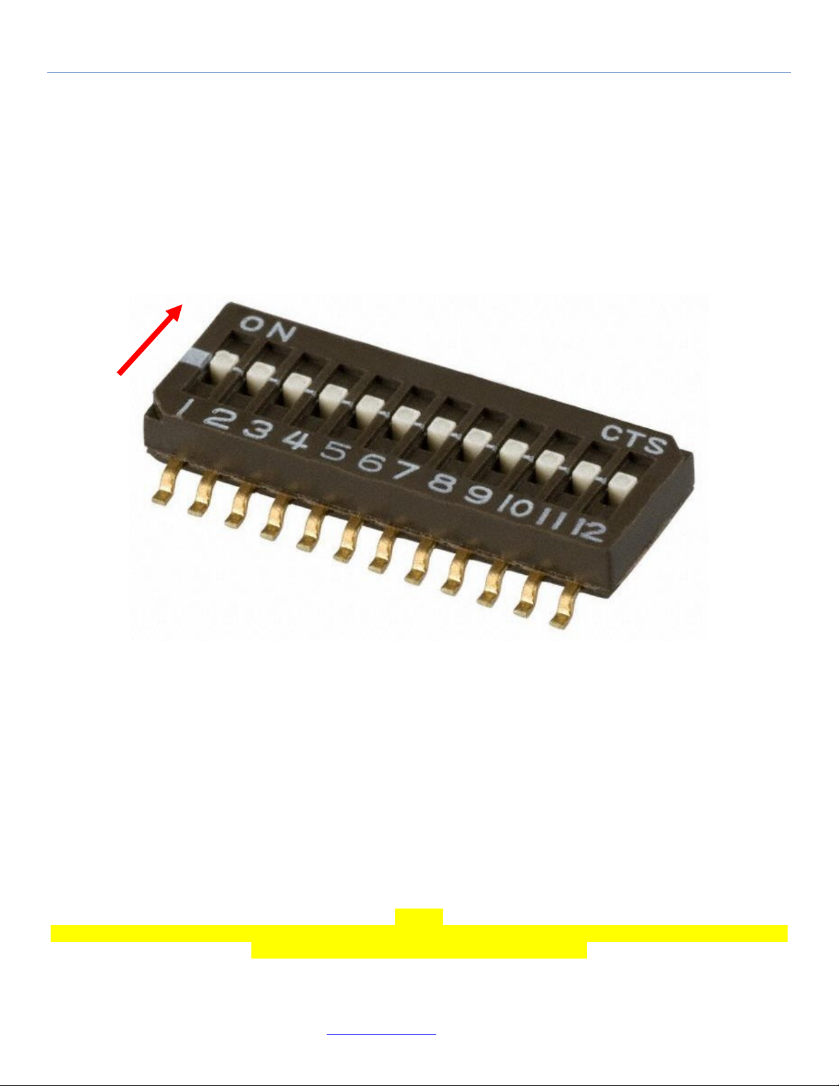
Profile Selector:
(Usage = Manual)
The SBT-4K allows the user to reconfigure the behavior of the profile on the fly with its 12 selectable slide switches. Figure 1 shows
the slide switch. From left to right are positions 1 thru 12. The red arrow depicts toggle position 1 located far left. Shown in the “ON”
up position.
(Figure 1)
Below is the order of the 5 attributes and number of variables associated within:
Attribute #1 GRACE_PERIOD position 1, 2 4 variables (Page 6)
Attribute #2 FREQUENCY position 3, 4, 5 8 variables (Page 7)
Attribute #3 MODULATION position 6, 7, 8 8 variables (Page 8)
Attribute #4 SLOPE position 9, 10 4 variables (Page 9)
Attribute #5 DECAY position 11, 12 4 variables (Page 10)
To see a detailed listing of their variables go to page number as listed above.
Caution:
Testing the attributes may cause the battery to discharge. Consider running the engine while doing such configuration. Make sure to
have good air ventilation when performing such tests inside.
Page 6 of 24
Contact email@vizi-tec.com for more information
 Loading...