

Page 1
-40 х
-40 А-2
-40 А-4
-40 С -2
-40 С -4
С
VIZIT®
VIZIT-М
25
:
-- ;
-- ;
--
-- .
:
-;
-;
-;
- 400.
.
Doorstation is intended for operation in VIZIT doorphones / video doorphones (Series Comfort).
The following models are available
doorstation to connect 2 apartment handsets
doorstation to connect 4 apartment handsets
video doorstation with colour camera to connect 2 video monitors;
video doorstation with colour camera to connect 4 video monitors
Abbreviations used in the model names
No camera
Colour camera
- Pinhole lens.
Individual CALL button for subscribers
Beep in the doorstation and monitor / apartment handsets when the CALL button is pressed.
Duplex intercom
Door zone video monitoring ( and )
Remote door unlockingbypressing the button on the monitor / apartment handset during intercom
Beeps to indicate door lock release
IR illumination for the camera ( and )
Lighting for the nameplate
Subscriber devices are trademarked products:
apartment handsets
video monitors of Series
The product does not contain voltage above
Do not make any connections or repair when the power is on.
Take care not to spill any liquids or chemically active substances on the product.Switch the power off before cleaning the
product. Clean by wiping with dry soft cloth. Do not use any liquid cleaners, aerosol cleaners or abrasive agents.
BVD 5
BVD 5 UKP
BVD 5 UKP
BVD 5 P
BVD 5 P
A
P
FEATURES
BVD-405CP-2 BVD-405CP-4
BVD-405CP-2 BVD-405CP-4
UKP
SAFETY INSTRUCTIONS
V
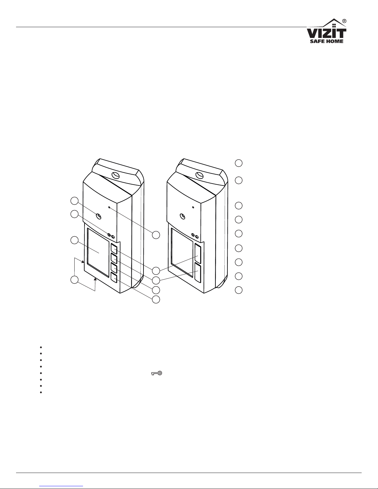
1 -Figure Doorstation BVD-405x
8
CALL button for Apartment 2
7
CALL button for Apartment 1
6
CALL button for Apartment 3
1
2
3
4
8
9
9
Microphone
7
6
5
5
Speaker
4
CALL button for Apartment 4
3
Niche for nameplate
1
Colour camera
BVD 5CP-2(4))( -40
2
IR LEDs
illumination for camera in(
BVD 5CP-2(4))-40
BVD 5CP--40 4,
BVD 5 --40 А 4
BVD 5CP--40 2,
BVD 5 --40 А 2
www.vizit.eu BVD 5x-40
1/11
OPERATING INSTRUCTION
BVD 5x-40
OPERATING INSTRUCTION
Page 2
INSTALLATION ORDER
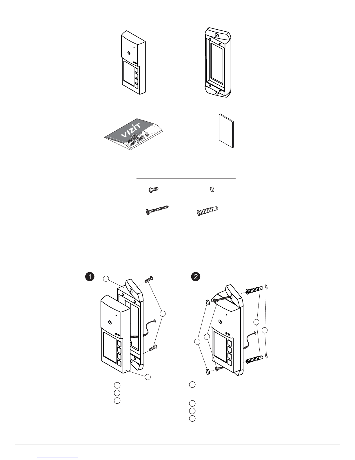
The doorstation is mounted on a wall near your entrance door. The skew base provides turn and allows either left-
side or right-side mounting
20°
. To protect the doorstation against sun, rain or snow, installation of specially designed Mounting
Kit MK-405 is recommended. Installation order of the doorstation together with its sun/rain shield is described in the
Mounting Kit MK-405 installation manual.
Doorstation BVD 5-40 х
Skew Base
Operating Instruction
x1
x1 x1
PARTS LIST
x1
Blank nameplate
Fasteners
Screw 6М4х1
Screw - 4х40
Anchor
for doorstation BVD 5 and skew base-40 х
x2
x2 x2
Gag
x 4
Figure 2 Doorstation wall-mounting on the left from the entrance door-
6
4
5
7
Hole
mm in diameter
mm deep
()
6
40
х2
Anchor ( )х2
Screw - 4х40 ( )х2
Gag ( )х2
1
2
3
Doorstation
Skew base
Screw 6М4х1 ( )х2
4
5
7
6
2
1
3
Fasteners are supplied.
www.vizit.eu BVD 5x-40
2/11
OPERATING INSTRUCTION
Page 3

Figure 3 Doorstation wall-mounting on the right from the entrance door-
- "-" 1
- "-" 2
- "-" 3
- "-" 4
- ( 40 );
FA
FB
FC
FD
VO
Line to Apartment ;
Line to Apartment ;
Line to Apartment ;
Line to Apartment ;
video out for BVD- 5CP-x
L N
LC
GND
+Е
IE-;
-
-
-;
intercom line
lock control
ground
supply voltage for doorstation
Figure 4 Terminals layout and marking-
L NIE
GND
+Е
VO
LC
FA
FB
FC
FD
www.vizit.eu BVD 5x-40
3/11
OPERATING INSTRUCTION
Page 4
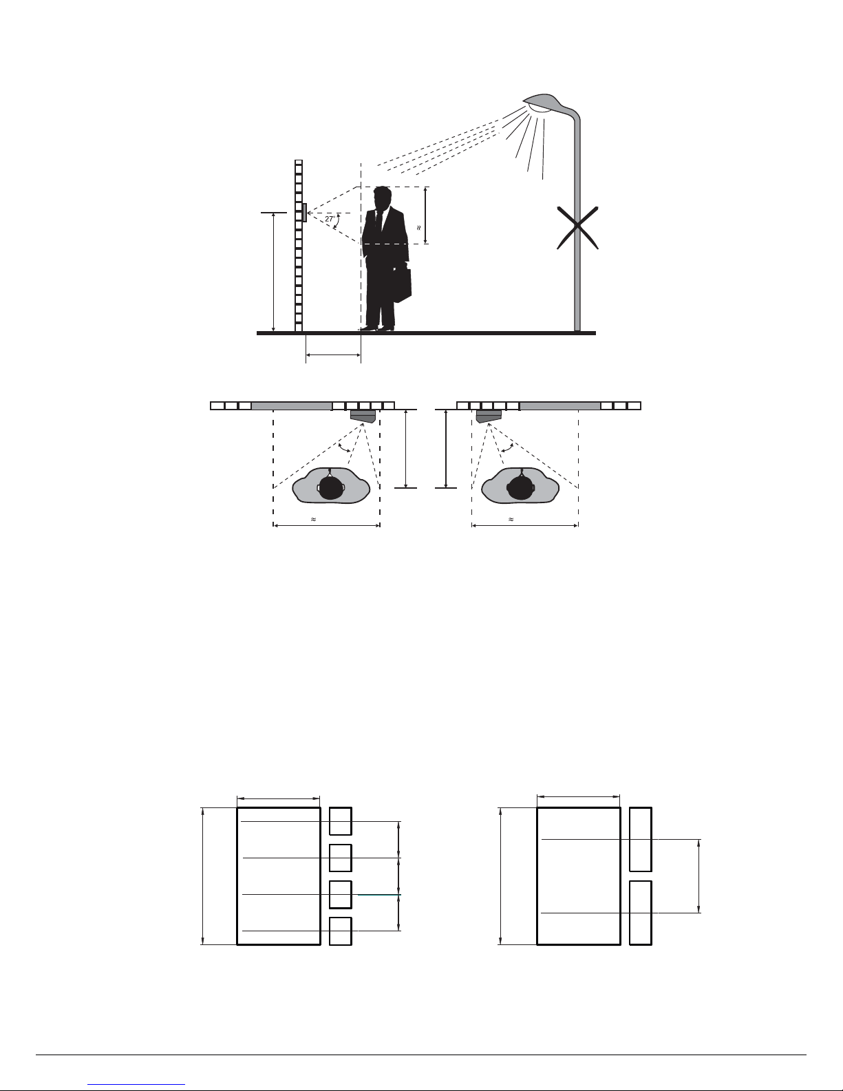
Locate the doorstation so as to avoid
‘EXAMPLES OF WIRING DIAGRAMS’
‘EXAMPLES OF WIRING DIAGRAMS’
:
-;
.
direct rays of the sun or other sources of light
- direct hit of rain or snow
Wiring diagrams for doorphone / video doorphone are shown in the section .
Use copper wires for connections in accordance with the recommended lengths and cross-sections given in the section
.
To reduce possibility of external noises influencing image, use 75-Ohm coaxial cable for video circuits.
NOTE
The doorstation is supplied wit a blank nameplate. The nameplate is a two-layer plastic plate with black base and silver
top layer. It is intended to have inscriptions on it, such as dwellers’ names, apartment or office numbers, company names
etc. Inscriptions are made by laser engraving, with removing silver layer and revealing the black base. Please refer to a
specialist to have the inscriptions made. Pattern and dimensions for laser engraving are shown on Figure 6.
Figure Pattern and dimensions for laser engraving on the nameplate
The nameplate is fixed in the niche in the doorstation’s front panel. To ensure proper fixing, clean the surface of the niche
with alcohol, then remove the protective film from the adhesive tape on the nameplate’s back, and firmly attach the
nameplate in the niche.
6 -
34°
50 cm
34°
50 cm
Figure 5 Recommended doorstation position
and camera field of view
-
150
cm
50
cm
80
cm
80
cm
5
cm
0
13.5
13.5
13.5
27
50.5
30.5
50.5
30.5
www.vizit.eu BVD 5x-40
4/11
OPERATING INSTRUCTION
Page 5
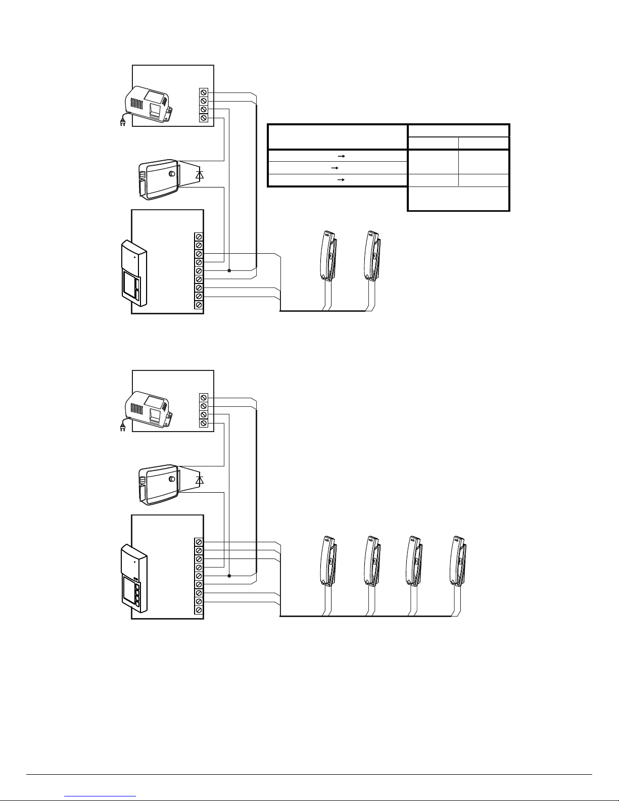
Figure 8 - 4-apartment doorphone
Figure 7 2-apartment doorphone-
LINE
LC
FB
+E
FA
GND
-
+
-
+
FD
FC
UKP UKP
-40
Doorstation
BVD 5A-2
+E
GND
FA
FB
LN
LN LNFA FB
EXAMPLES OF WIRING DIAGRAMS
V1A50
+E
GND
E
LECTROMECHANICAL
LOCK
V
MAX
(12 , 1А .)
Power Supply
18/12- -1BPD 1
-18
+18
+12
-12
LINE
LC
FB
+E
FA
GND
-
+
-
+
FD
FC
UKP UKP
-40
Doorstation
BVD 5A-4
+E
GND
FA
FB
LN
LN LNFA FB
V1A50
+E
GND
E
LECTROMECHANICAL
LOCK
V
MAX
(12 , 1А .)
Power Supply
18/12- -1BPD 1
-18
+18
+12
-12
-
+
-
+
UKP UKP
LN LNFC FD
Circuit length m,
Circuits
25
BPD 118/12- -1 -405А-2BVD
0.25 0.5
50
BVD-405А-2 UKP
Min. wire cross-
section, mm
BPD 118/12- -1 Lock
0.5 1.0
FC
FD
Apt. 1 Apt. 2 Apt. 3 Apt. 4
Apt. 1 Apt. 2
2
VO
VO
www.vizit.eu BVD 5x-40
5/11
OPERATING INSTRUCTION
Page 6
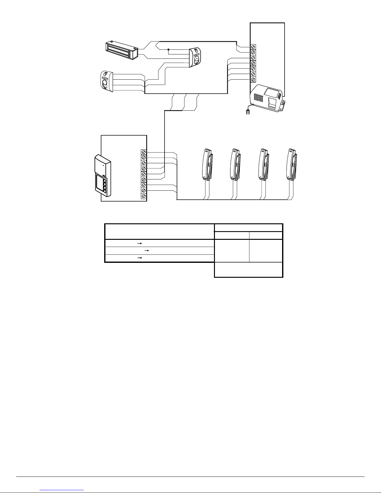
Figure 9 - VIZIT-KTM60 R24-apartment doorphone with RF controller
LINE
LC
FB
+E
FA
GND
-
+
-
+
FD
FC
UKP
UKP
+E
GND
FA
FB
LN
LN LNFA FB
-
+
-
+
UKP UKP
LN LNFC FD
FC
FD
LC
-40 4
Doorstation
BVD 5A-
-DL
+DL
BIP
ELC
RD
GND
OP
Reader
RD-3
Black
White
Blue
Red
Green
Button
МEXIT 300
Black
White
Blue
Red
Control
Unit
KТМ602М
+E
GND
LC
+E
LC
GND
-DL
+DL
Electromagnetic
lock VIZIT-ML400
+DL
-DL
+E
LC
LC
GND
GNDGND
+E
RD
RD
BIP
BIP
Circuit length, m
Circuits
25
KTM602M -405А-4BVD
0.25 0.5
50
BVD-405А-4 UKP
Min. wire cross-
section, mm
KTM602M VIZIT-ML400
Apt. 1 Apt. 2 Apt. 3 Apt. 4
2
VO
www.vizit.eu BVD 5x-40
6/11
OPERATING INSTRUCTION
Page 7
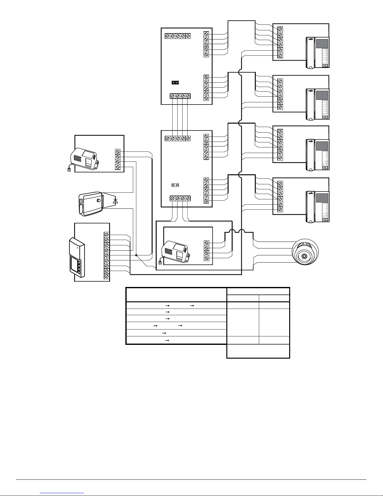
Figure 10 - 4-apartment video doorphone with outdoor camera and
video monitors powered from group power supply unitVIZIT*
Power Supply
/12- -1BPD24 1
-24
+24
+12
-12
Yellow
Black
Red
Black
VI
VG
+12
-12
LN
FC
FD
FA
FB
+E
GND
BVD 5A-4-40
LINE
LC
FB
+E
FA
GND
FD
FC
GND
P
VG
Ec
VI
VGM
Ec
VO
VGM
+E
GND
P
VI
+12
VG
GND
Ec
VO
VGM
+E
GND
P
VI
VG
GND
RVS-2
Distribution
Amplifier
XP1
GND
+E
Jumper has to be
left in place only in top
on this diagram.
XP1
RVS-2
LN-
GND
LN+
VI1
+E
Ec1
Monitor
VIZIT*
LN
FD
+E
VI
VGM
GND
Ec
LN-
GND
LN+
VI1
+E
Ec1
Monitor
VIZIT*
Ec
VI
VGM
+E
LN
FC
+E
VI
VGM
GND
Ec
GND
Ec
VI
VGM
Ec
VO
VGM
+E
GND
P
VI
+12
VG
GND
Ec
VO
VGM
+E
GND
P
VI
VG
GND
RVS-2
Distribution
Amplifier
XP1
GND
+E
LN-
GND
LN+
VI1
+E
Ec1
Monitor
VIZIT*
LN
FB
+E
VI
VGM
GND
Ec
LN-
GND
LN+
VI1
+E
Ec1
Monitor
VIZIT*
Ec
VI
VGM
+E
LN
FA
+E
VI
VGM
GND
Ec
GND
GND
P
VI
VG
Outdoor Camera
AP-143G
+12
-12
V1A50
+E
GND
E
LECTROMECHANICAL
LOCK
V
MAX
(12 , 1А .)
Power Supply
18/12- -1BPD 1
-18
+18
+12
-12
Circuit length, m
Circuits
25
0.25 0.5
50
BVD A-405 -4 Monitors
Min. wire cross-
section, mm
BPD 1 Lock18/12- -1
BPD 118/12- -1 -405 -4BVD A
0.5 1.0
BPD24/12-1-1 RVS 2 Monitors-
BPD24/12-1-1 AP-143G
AP-143G RVS 2- Monitors
0.5 1.0
Apt. 1
Apt. 2
Apt. 3
Apt. 4
2
VO
* - video monitors that may be
used in this diagram:
VIZIT-M4 VIZIT-M4
VIZIT-M4 VIZIT-M4
VIZIT-M4
30C, 40C,
40CM, 56C,
56CM.
www.vizit.eu BVD 5x-40
7/11
OPERATING INSTRUCTION
Page 8
V1A50
LN
FC
FD
FA
FB
+E
GND
+E
GND
-40BVD 5CP-4
LINE
LC
FB
+E
FA
GND
FD
FC
VO
Power Supply
18/12- -1BPD 1
-18
+18
+12
-12
GND
P
VG
VI
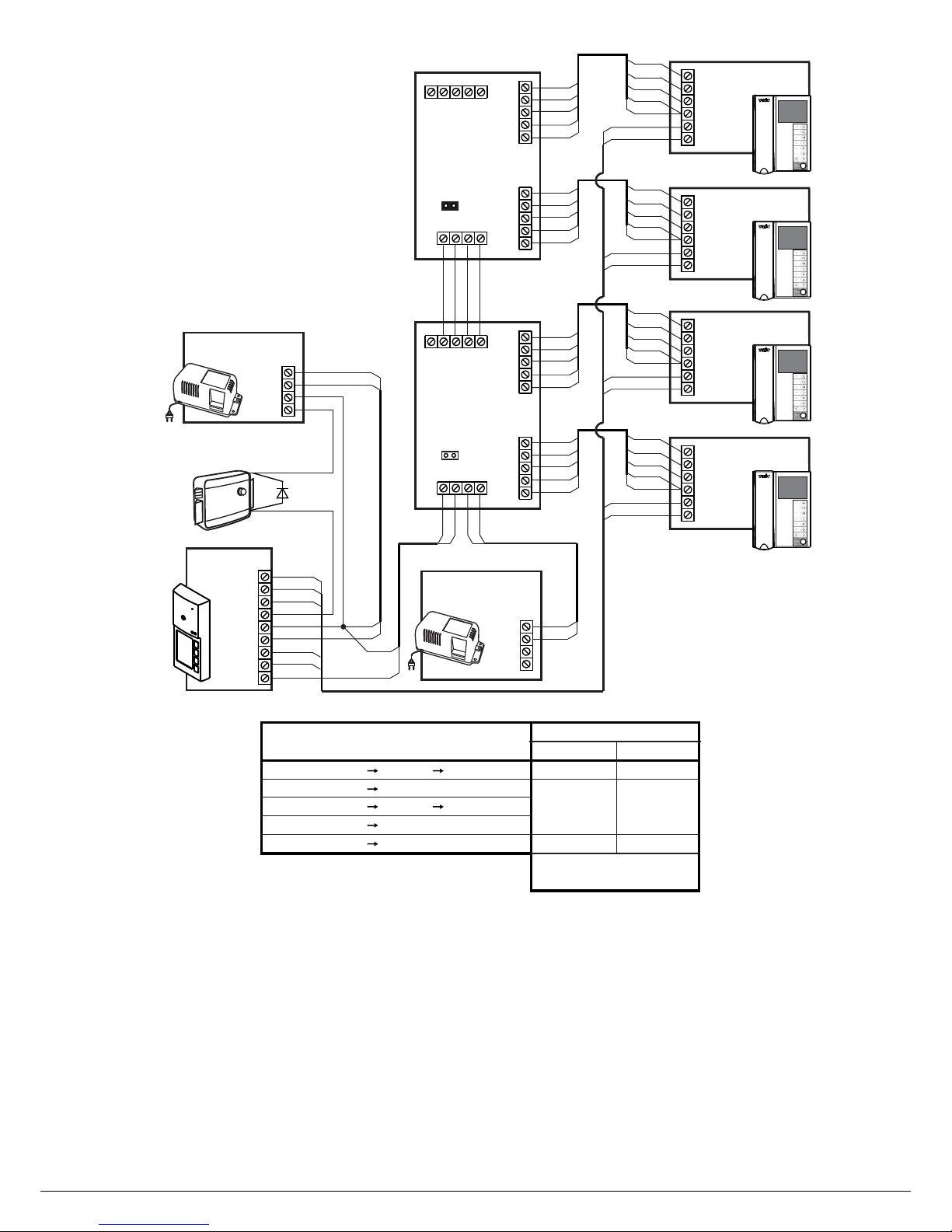
Figure 11 - 4-apartment video doorphone with video monitors
powered from group power supply unit
VIZIT*
ELECTROMECHANICAL
LOCK
V MAX(12 , 1А .)
Ec
VI
VGM
Ec
VO
VGM
+E
GND
P
VI
+12
VG
GND
Ec
VO
VGM
+E
GND
P
VI
VG
GND
RVS-2
Distribution
Amplifier
XP1
GND
+E
Jumper has to be
left in place only in top
on this diagram
XP1
RVS-2
LN-
GND
LN+
VI1
+E
Ec1
Monitor
*VIZIT
LN
FD
+E
VI
VGM
GND
Ec
LN-
GND
LN+
VI1
+E
Ec1
Monitor
VIZIT*
Ec
VI
VGM
+E
LN
FC
+E
VI
VGM
GND
Ec
GND
Ec
VI
VGM
Ec
VO
VGM
+E
GND
P
VI
+12
VG
GND
Ec
VO
VGM
+E
GND
P
VI
VG
GND
RVS-2
Distribution
Amplifier
XP1
GND
+E
LN-
GND
LN+
VI1
+E
Ec1
Monitor
VIZIT*
LN
FB
+E
VI
VGM
GND
Ec
LN-
GND
LN+
VI1
+E
Ec1
Monitor
VIZIT*
Ec
VI
VGM
+E
LN
FA
+E
VI
VGM
GND
Ec
GND
GND
P
VI
VG
Power Supply
BPD18/12- -11
-18
+18
+12
-12
Circuit length, m
Circuits
25
0.25 0.5
50
BVD CP 2-405 -4 -RVS Monitors
Min. wire cross-
section, mm
BPD 1 Lock18/12- -1
BPD 118/12- -1 -405 -4BVD CP
0.5 1.0
BPD18/12-1-1 RVS 2 Monitors-
BVD CP-405 -4 Monitors
0.5 1.0
Apt. 1
Apt. 2
Apt. 3
Apt. 4
2
* - video monitors that may be used
in this diagram:
VIZIT-M4 VIZIT-M4
VIZIT-M4 VIZIT-M4
VIZIT-M4
30C, 40C,
40CM, 56C,
56CM.
www.vizit.eu BVD 5x-40
8/11
OPERATING INSTRUCTION
Page 9
LN-
GND
LN+
VI1
+E
Ec1
LN-
GND
LN+
VI1
+E
Ec1
Monitor
VIZIT*
Monitor
VIZIT*
LN
FA
FB
+E
GND
Ec
VI
VGM
LN
FB
+E
VI
VGM
GND
LN
FA
VG
VI
-40BVD 5CP-2
LINE
LC
FB
+E
FA
GND
FD
FC
VO
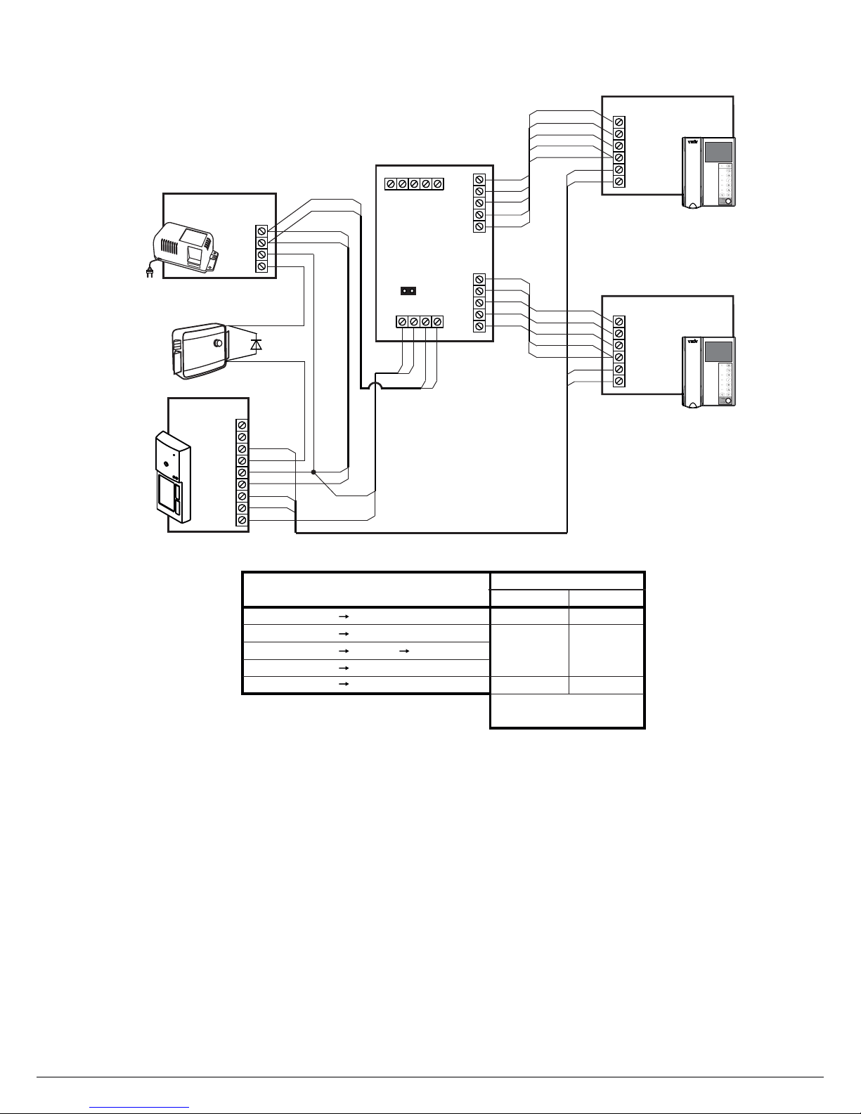
Figure 12 - 2-apartment video doorphone
Ec
VO
VGM
+E
GND
P
VI
+12
VG
GND
Ec
VO
VGM
+E
GND
P
VI
VG
GND
RVS-2
Distribution
Amplifier
XP1
GND
+E
Ec
Ec
VI
VGM
GND
+E
+E
VI
VGM
GND
Ec
VGVIGND
P
Jumper in RVS-2
has to be set in place
XP1
V1A50
+E
GND
ELECTROMECHANICAL
LOCK
V MAX(12 , 1А .)
Power Supply
18/12- -1BPD 1
-18
+18
+12
-12
Circuit length, m
Circuits
25
0.25 0.5
50
BVD CP 2-405 - -2RVS Monitors
Min. wire cross-
section, mm
BPD 1 Lock18/12- -1
BPD 118/12- -1 -405 -2BVD CP
0.5 1.0
BVD CP 2-405 - Monitors
BPD 118/12- -1 Monitors
0.5 1.0
GND
P
Apt. 1
Apt. 2
2
* - video monitors that may be used
in this diagram:
VIZIT-M4 VIZIT-M4
VIZIT-M4 VIZIT-M4
VIZIT-M4
30C, 40C,
40CM, 56C,
56CM.
www.vizit.eu BVD 5x-40
9/11
OPERATING INSTRUCTION
Page 10
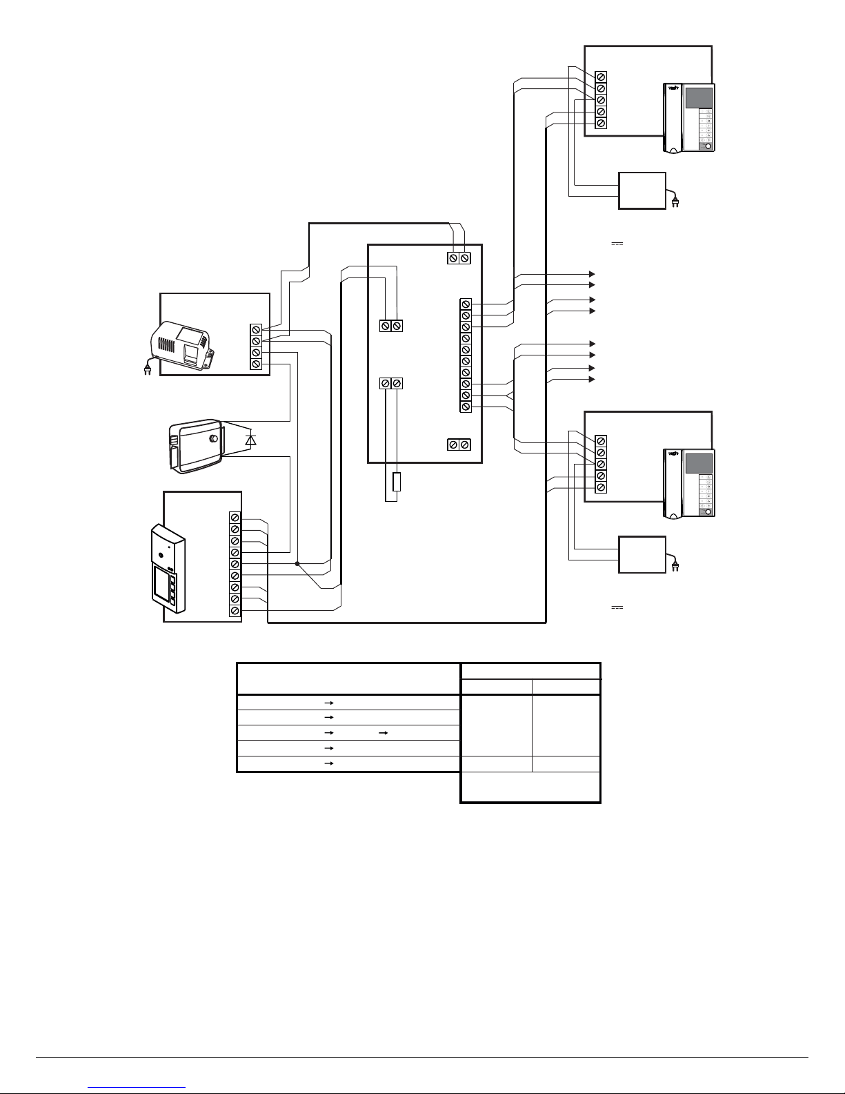
Figure 13 - 4-apartment video doorphone with monitors
powered from individual power supply units
VIZIT*
82 Оhm
RVS-4
Distribution
Amplifier
VG
+18
-18
VO
VG
V3
+18
VG
V1
V2
-18
-18
+18
V4
VG
VI
+18
-18
LN-
GND
LN+
VI1
+E
Monitor
*VIZIT
* - video monitors that may be used
in this diagram:
VIZIT-M4 VIZIT-M4
VIZIT-M4 VIZIT-M4
VIZIT-M4
30C, 40C,
40CM, 56C,
56CM.
LN
FC
FD
FA
FB
+E
GND
VG
VI
VG
V1
V2
V3
V4
VG
LN
FD
V1
VG
LN
FC
V2
VG
LN
FB
V3
VG
LN
FA
V4
VG
-40BVD 5CP-4
LINE
LC
FB
+E
FA
GND
FD
FC
VO
-18 +18
VG
VI
+18
-18
+E
GND
LN-
GND
LN+
VI1
+E
Monitor
VIZIT*
+E
GND
To monitor
VIZIT*
To monitor
VIZIT*
V1A50
+E
GND
E
LECTROMECHANICAL
LOCK
V
MAX
(12 , 1А .)
Power Supply
BPD 118/12- -1
-18
+18
+12
-12
Circuit length m,
Circuits
25
0.25 0.5
50
BVD CP-405 -4 -4RVS Monitors
Min. wire cross-
section, mm
BPD 1 Lock18/12- -1
BPD 118/12- -1 -405 -4BVD CP
0.5 1.0
BPD 118/12- -1 RVS-4
BVD CP-405 -4 Monitors
Apt. 1
Apt. 4
2
18 , А
Power Supply Unit
19w/14.4v/EU(18V/1.0A)
V 1
18 , А
Power Supply Unit
19w/14.4v/EU(18V/1.0A)
V 1
www.vizit.eu BVD 5x-40
10/11
OPERATING INSTRUCTION
Page 11

FUNCTIONAL CHECK AND OPERATING ORDER
Note.
SPECIFICATIONS
VDC
W max.
60 x 60 x 43 mm
.3 kg
.kg
OPERATING CONDITIONS
-+
- 3 +
.
.
:
40
:
- -40 А
- -40
Before switching the power on, verify all electric connections.
• Turn the power supply unit(s) on.
• To make a call to the subscriber, press one of the CALL buttons on the doorstation. A call sound rings both in the
corresponding monitor (apartment handset) and doorstation, while the CALL button remains pressed. Image appears on
the monitor’s screen.
Pick up the handset and check duplex intercom.
Check image on the monitor’s screen. Adjust imagebrightness, contrast and saturation, if needed.
Press the on the monitor (apartment handset) to release the door lock.The doorstation produces a beep, and the
lock stays released while the buttonremains pressed. Release the button to return to the intercom mode.
Hang up the handset The system goes to the stand-by mode.
When called, the subscriber can press the buttonto release the door lock without picking up the handset.
The system goes to the stand-by mode after the button is released.
Intercom is available within seconds after picking up the handset.
If the handset is not picked up in 60 seconds, the system returns to the stand-by mode automatically
• One by one check the rest of connected apartment handsets / monitors for intercom, video (for monitors), remote door
unlocking function.
Operating voltage:
Power consumption:
Dimensions (W)x(H)x(D):
Weight:
Weight with package
The built-in camera parameters (BVD- 5CP-x) are given below:
Ambient temperature range
BVD 5 -2(4) to
BVD 5CP-2(4) to
Relative humidity of air: up to at
(60 ± 5)
16...25
3
1
0
0 4
40°C 45°C
0°C 45°C
98% 25°C
Camera Parameters
Lens
Angle of view (diagonal)
Colour system
Scanning system
Resolution
Minimal illumination
PAL
СCIR
380 TVL
0 Lux (IR LED on
. m range)
. Lux IR LED off
0 5
0 5 ( )
Pinhole
90°
Day-Night feature
YES
Output voltage
175ОVp-p at hm
www.vizit.eu BVD 5x-40
11/11
OPERATING INSTRUCTION
 Loading...