

BKM 1
Commutator BKM 1 VIZIT
VIZIT
FEATURES
List of devices compatible with BKM-441
19w/14.4v/EU(18V/1.0A)
BPD BPD
VIZIT
BVD
VIZIT
BK -4MV MVE, -4AV, RVS RVS , RVS-4M, -RVE-4
VIZIT
Note. Only monitors VIZIT of year of production and later will support
the full rangeof the Commutator’s functions describedin this operating instruction.
produced before April 2013, and monitors VIZIT-456C produced in 2013 will have limited functions
with the Commutator BKM-441 such as: selection of an individual ring tone for a DOOR BELL button is not
available. For the calls from the DOOR BELL button, the ring tone will be the same as selected for an individual
doorstation.
PARTS LIST
BKM
SAFETY INSTRUCTIONS
24V
INSTALLATION
-44
-44
18/12-1-1 24/12-1-1
-401, -403, -405,-406, -407, -410, -411
-4М, ,-4 -10, -30М, -100М, -2, -4
-М440С -М440СМ -М456С -М456СМ -МТ460СМ
-М440С -М440СМ -М456СМ -МТ460СМ 2013
,
-441 1
1
OPERATING INSTRUCTION
()
:
-
-
-
-
,.
:
.
:
.
:,,,,.
,,,
the Commutator hereinafter is intended to connect monitors to video and intercom lines
within videodoorphones.
Connection of callingdevices to the apartment monitor
the main entrancemulti-apartment video doorstation (intercom andvideo)
an individual doorstationon the storey (intercom andvideo)
a DOOR BELLbutton at the apartment door
Option to connectan electromechanical lock or strike
Power supply unit regulated, 18V/1A. Other acceptable power supply units:
All models withinthe following model lines ofindividual video doorphones
Commutators and distributionamplifiers part of multi-apartment videodoorphones
ADOOR BELL button -a button with normally opencontacts
Colour video monitors
Electromechanical locks and trigger strikes, which have fail-locked with hold-open function. The lock/ strike is
unblocked after a short power impulse, and remains unblocked even when the power is off. The lock / strikes becomes
blocked again, afterthe door is opened andthen closed again.
Commutator pc.
Operating instruction pc.
The Commutator doesnot contain voltage above .
Do not perform any connections or repair when the power is on.
The Commutator shall be installed in heated premises with sufficient ventilation. The Commutator may be fixed either on
a wall, oron a DIN-rail.
v
v
v
v
v
v
v
v
All monitors
For qualified installation, wiring and servicing refer to technical and commercial partners of VIZIT TM.
The list of companies is given on VIZIT.EU ( .http://vizit.eu/eurounion/)
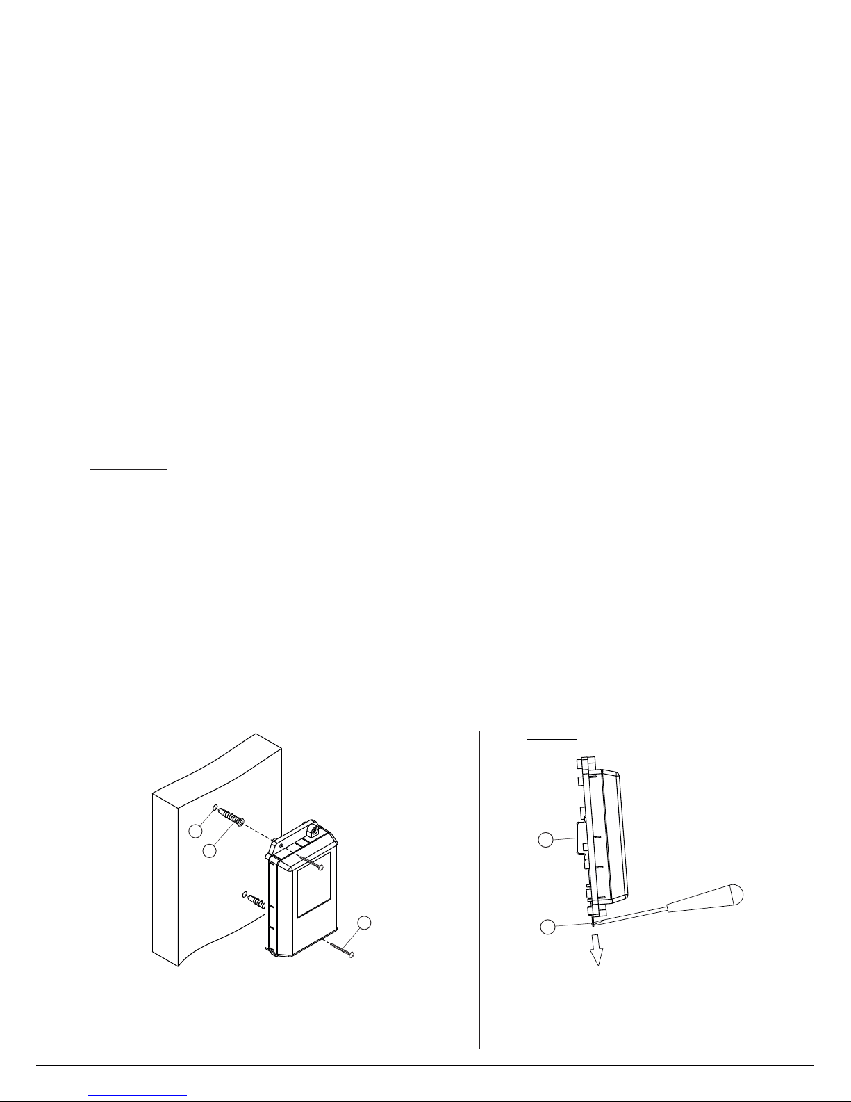
- Drill 2 holes in a wall, with 6 mm diameter and mm depth.
- Drive anchors (2) into the holes
Fix the unit by fastening 2 screws 25 in the anchors
(1) 30
6х30 .
- 3.5х (3) .
(1) - DI - 35 1-2
(2) - -
rail, width mm, depth mm
Holder for fixing on a DIN rail
N
1
2
1
2
3
Figure1 - Mounting on a wall Figure 2 - Mounting on a DIN-rail
Note. Fasteners are not supplied.
www.vizit-group.com BKM-441 Operating Instruction (revision 11 52015- ) 1/

CONNECTIONS
EXAMPLES OF WIRINGDIAGRAMS.
Notes
19w/14.4v/EU(18V/1.0A)
19w/14.4v/EU(18V/1.0A)
GND
+E GND
BPD1 + V
+E V GND
BPD + V
+E GND GND
BVD BUD UKP Monitor
.
+Е
8/12-1-1 18
-18
24/12-1-1 24
() ( )
.
3 -
1.
.
(
.
2.
3.
().
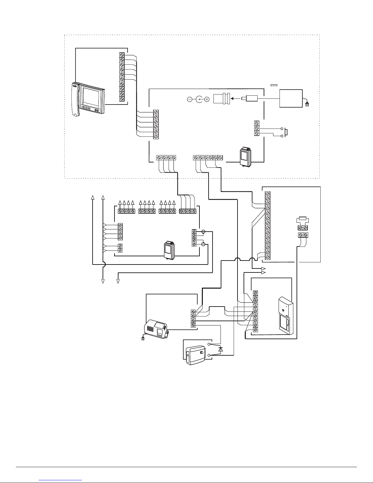
· Video doorphone cables are connected to the Commutator’s terminals and DC input onits PCB To access the PCB and
DC input, take off the Commutator’s cover. Make connections following wiring diagrams given in the section
Figure Terminals layout, names and destinations.
To extend a cable between the power supply unit and Commutator, use the in-line DC jack
supplied with the unit Connect a two-wire cable of required length to the DC jack contactsand
terminals and of group (1) or (3) on the Commutator’s PCB the central contact of the DC jack
shall be connected to terminal, the side contact to
If use the power supply unit , connect terminal of the power supply unit to one of the
Commutator’s terminals, and terminalof the power supply unitto one of the Commutator’s terminals.
If use the power supply unit , connect terminal of the power supply unit to one of the
Commutator’s terminals, and terminal of the powersupply unit to one ofthe Commutator’s terminals.
Acceptable wire cross-sections to connect the Commutator to doorstations / control units are given in their operating
instructions see:
To connect monitors to the Commutator, use copper wires with regard to the acceptable cross-sections given below:
«
+E
VO
LN1+
GND
LN2+
LN2-
+E
Ec2
LN+
GND
LN-
VI1
LN1-
DATA
GND
VI2
DBB
+DL
GND
Commutator
BKM-441
1
3
4
2
GND +E
DC IN
5
(1) - .
(2) -
Terminals to connect a monitor
Terminals to connect intercom and video from the
multi-apartment video doorphone
Terminals to connect an individual video doorstation.
Terminals to connect a DOOR BELL button and
electromechanical lock / strike
DC input from the power supply unit
.
(3) (4) -
(5) -
.19w/14.4v/EU(18V/1.0A)
Terminals
Circuit
LN 1-
LN 1+
GND
GND
+E
GND
Intercom line from commutator of the multi-apartment
video dooephone
Destination
Supply voltage to Monitor
Ground
Ground
Ground
(
)
Address
see the section List of
devices compatible with
BKM 1-44
To Monitor
To DOOR BELL button and
electromechanical lock / strike
1
2
3
DATA
To commutator / distribution
amplifier of multi-apartment
video doorphone
LNLN+
VO
VI1
Video input
DBB
Connection of DOOR BELL button
4
+DL
Supply voltage to electromechanical lock / strike
GND
Ground
LN 2+
Intercom from individual video doorstation
LN 2-
+E
VI2
Video input from doorstation camera
Ec2
To individual video doorstation
Intercom line to Monitor
Data exchange between Commutator and Monitor
Video output to Monitor
Supply voltage to doorstation camera
Supply voltage to individual doorstation
CIRCUIT
Wire
Max. length, m
0.07
Cross-section, mm
2
0.2 0.5
BKM Monitor-441 -
51540
0.3
Diameter, mm
0.5 0.8
www.vizit-group.com BKM-441 Operating Instruction (revision 11 2 52015- ) /
EXAMPLES OF WIRING DIAGRAMS
Figure Commutator with monitor doorstation on the storey
DOOR BELL button and multi-apartment (main entrance) video doorphone
4 - BKM BVD-441 ,(),VIZIT -405СР-2
1
4
2
1
2
2
1
3
To next commutators
BK-4MV
To other apartments on the storey
VO
VG
VG
-18
+18
V4
FD
LN
VG
V3
FC
LN
VG
V2
FB
LN
VG
V1
FA
LN
VG
GND
LINE
SEL
Ek
VI
Commutator
BK-4MV
1
4
3
2
5
6
1
4
3
2
VG
V1
+18
V2
-18
V3
+18
V4
VG
-18
VG
VI
VO
VG
-4
Distribution
Amplifier
RVS
+18
-18
+18
-18
-40
Doorstation
BVD 5CP-2
LINE
LC
FB
+E
FA
GND
FD
FC
VO
82 Ohms
Power Supply Unit
18/12- -1BPD 1
-18
+18
+12
-12
2
1
1
2
2
1
1
12
2
2
1
2 1
2
1
1
2
1
2
To the next
apartment
50 V
1A
V
E
LECTROMECHANICAL
LOCK
(12 , 1А )
1
4
3
2
5
6
1
4
3
2
5
6
-441BKM can connect
monitors as follows:
- 440
- 440
- 456
- 456
- Т460
VIZIT M C
VIZIT M CM
VIZIT M C
VIZIT M CM
VIZIT M CM
Door Bell
button
Commutator
BKM-441
VI1
GND
LN1-
L1N+
GND
LN2-
+E
LN2+
VI2
Ec2
+E
GND
LN-
VO
LN+
DATA
GND
+DL
DBB
GND +E
DC IN
18 , А
Power Supply Unit
19w/14.4v/EU(18V/1.0A)
V 1
To doorstation / control unit
(see wiring diagrams given
in operating instructions on
control units or doorstations
of multi-apartment
doorphones / video
doorphones VIZIT)
LN-
GND
LN+
VI1
+E
DATA
Ec1
Ec2
GND
VI2
Monitor
VIZIT
Apartment 1
www.vizit-group.com BKM-441 Operating Instruction (revision 11 3 52015- ) /

Figure , ( ),VIZIT -405 - Commutator with monitor doorstation on the storey
DOOR BELL button and multi-apartment (main entrance) video doorphone
BKM BVD 3CPL-441
1
4
3
2
5
6
LN-
GND
LN+
VI1
+E
DATA
Ec1
Ec2
GND
VI2
Monitor
VIZIT
1
4
3
2
5
6
To next
commutators
BK-4MV
VO
VG
VG
-18
+18
GND
LINE
SEL
Ek
VI
Commutator
BK-4MV
To doorstation / control unit
(see wiring diagrams given in operating
instructions on control units or doorstations
of multi-apartment doorphones / video
doorphones VIZIT)
1
4
3
2
5
6
1
2
3
4
Doorstation
BVD 403CPL-
1
43
2
-441BKM can connect
monitors as follows:
- 440
- 440
- 456
- 456
- Т460
VIZIT M C
VIZIT M CM
VIZIT M C
VIZIT M CM
VIZIT M CM
LINE
GND
+E
VO
Ec
LC
5
5
50 V
1A
V
E
LECTROMECHANICAL
LOCK (12 , 1А )
Door Bell
button
18 , А
Power Supply Unit
19w/14.4v/EU(18V/1.0A)
V 1
Commutator
BKM-441
VI1
GND
LN1-
L1N+
GND
LN2-
+E
LN2+
VI2
Ec2
+E
GND
LN-
VO
LN+
DATA
GND
+DL
DBB
GND +E
DC IN
1
4
2
3
To other apartments on the storey
V4
FD
LN
VG
V3
FC
LN
VG
V2
FB
LN
VG
V1
FA
LN
VG
1
4
3
2
www.vizit-group.com BKM-441 Operating Instruction (revision 11 4 52015- ) /

FUNCTIONAL CHECK AND OPERATION
Plug in the power supply unit
Monitor settings
Loop video monitoring of door zone in front of cameras
Calls from doorstation
Note.
Calls from DOOR BELL button
Simultaneous calls
Activation of individual (1-subscriber) doorstation
Calls to the Concierge
VIZIT
SPECIFICATIONS
VDC
W
W
W
mm
mm
mm
.kg
OPERATING CONDITIONS
++
Before turning the power on, make sure that there is no misconnection or risk of short circuit.
Check the power supply unit’s LED lighting up. After switching on, the Commutator is automatically scanning all video inputs
to exclude vacant channels from loop video monitoring. This process takes approximately 10 seconds. After the check-up,
the Commutator isready for operation.
A full guide on how to perform monitor settings is given in the operating instruction on your monitor.
To start loop video monitoring (when the handset is hung up), push repeatedly the video monitoring button on the monitor.
Images from connected cameras appear on the screen repeatedly. If one of video inputs is vacant, i.e. not connected to any
video device, itis automatically skipped from viewing.
If you are pushing the video monitoring button with the picked up handset, the screen is showing images from all cameras
one by one,though a vacant video channelis from viewing, showing ablack screen.
When a call is made from one of the doorstations connected to the Commutator, the monitor is ringing, the screen is
displaying image fromthe doorstation’s camera.
Pick up thehandset from the monitor andcheck duplex intercom.
To release the door lock, press and hold the button on the monitor until a short beep. The door is unlocked now. After
you release the button, intercom is still available. Hang up the handset: the screen switches off, the monitor and the
Commutator will goto stand-by.
You can unlock the door without picking up the handset. When the monitor is ringing, just press and hold
the button untila beep. The door is unlocked now.After you release , themonitor and the Commutator goto stand-by.
Functional check of the monitor operation with the second doorstation is done in the same manner.
When the DOOR BELL button is pressed, the monitor is ringing
If during intercom with one doorstation the Commutator has registered a call from the other doorstation, the Power LED
on the monitor starts blinking. To switch to the new call, push briefly the video monitoring button on the monitor.
To activate the individual doorstation (i.e., start intercom and video monitoring on your initiative), push repeatedly the video
monitoring button onthe monitor, until the screen displays image fromthe camera you need, andthen pick up the handset.
If the multi-apartment video-doorphone includes the Concierge Consol in its system, calls to the Concierge from your
monitor are available. (for details on “Subscriber Concierge” intercom pleaserefer to the Concierge Consoleoperation instruction)
Operating voltage
no more than
Power consumption withconnected devices, no more than
stand-by
at maximal load
Dimensions
width
height
depth
Weight
Ambient temperature range to
Relative humidity of air: up to at
.
.
.
-
-
-
-
-
:
17 ... 25
1
3
10
75
135
35
0 14
1°C 40°C
93% 25°C
not skipped
Pick up the handset from the monitor to start a call to the Concierge
Power consumption,
www.vizit-group.com BKM-441 Operating Instruction (revision 11 5 52015- ) /
 Loading...