

Raptor II Ruggedized PTZ
Instruction Manual version 2.1
Please read this manual carefully before installation and operation of the product.

VHT Raptor Manual Ver. 3.1
1
05th June 2012
Table of Contents
1. Introduction ----------------------------------------------------------------------------- 4
2. Safety Warning ------------------------------------------------------------------------ 5
3. Packing List ----------------------------------------------------------------------------- 7
4. Mounting ---------------------------------------------------------------------------------- 8
■ Mounting Options (UK_Column Mounting)
■ Offset Mounting
■ WIPER SET CHANGE
■ CABLE14PIN Connection
5. Telemetry Control ------------------------------------------------------------------- 12
■ On-Board Protocols
■ DIL (Dual In-Line) Switches
• Protocol Settings
• Baud Rate Settings
• RS485 Address Settings
• RS485 Termination
• Keyboard Operation
6. Setup Menu Overview ------------------------------------------------------------ 17
MAIN MENU ------------------------------------------------------------------------------ 21
■ PAN TILT SET
• ID DISPLAY
• P/T DISPLAY
• CAMERA NAME
• MANUAL SPEED
• PROPO. P/T
• DIGITAL FLIP
• IMAGE HOLD
• INSTALLATION
• AUTO REFRESH
• EXIT
■ CAMERA SET
• WDR
• MOTION DET
• ATW
• FOCUS / ZOOM

VHT Raptor Manual Ver. 3.1
2
05th June 2012
• AE
• DAY & NIGHT
• SPECIAL
• EXIT
■ AUTOSEQ SET
• PRESET
• TOUR
• SCAN
• PATTERN
• AUTO PAN
• AUTO RUN
• EXIT
■ ZONE SET
• AREA SEL
• AREA DEFINE
• AREA COLOR
• AREA NEW SET
• HEIGHT EDIT
• WIDTH EDIT
• PAN ANGLE
• TILD ANGLE
• EXIT
■ ALARM SET
• ALARM DISPLAY
• ALARM IN
• ALARM OUT
• TIME OUT
• EXIT
■ WIPER SET
• WIPER RUN
• EXIT
■ INITIALIZE SET

VHT Raptor Manual Ver. 3.1
3
05th June 2012
• POWER ON RESET
• PAN / TILT INIT
• CAMERA INIT
• AUTO SEQ INIT
• PRIVACY ZONE INIT
• FACTORY INIT
• EXIT
7. Specification------------------------------------------------------------------------ 44
8. Dimensions-------------------------------------------------------------------------- 46

VHT Raptor Manual Ver. 3.1
4
05th June 2012
1. Introduction
This unit is designed to provide clear video under all circumstances.
Robust mechanism with the latest technology realized an excellent auto-focus control
technology during PTZ operation a long time, an exact location control after preset
operation and high-speed zoom and auto focus capabilities for shooting a moving
objects. Installation of flat window and built-in wiper with over 550TVL provides a vivid
picture quality and zoom interlocking IR LED technology supplies an outstanding
performance for night monitoring environment and 128x Super WDR.
Long-distance objects can be distinguished by outstanding performance of X36
Optical Zoom and X12 Digital Zoom, totally x432 Power Zoom capability. Besides,
embedded 2 high power zooming LED’s work synchronized with optical zoom ratio to
figure out objects so precise to see even the human hair in fully dark night time. Builtin and adjustable de-fog function enables enhanced clear image even in the fog or
smog.
Features
■ 1/4” Sony EX-view HAD CCD
■ Powerful night vision up to 100M view
■ Zoom Interlocking IR LED (IR angle 6~50 degree, synchronized with optical
zoom ratio)
■ Embedded and adjustable defogger or image-enhancer
■ 128X Wide Dynamic Range
■ 2D and 3D DNR (Digital Noise Reduction)
■ Optical X36 zoom and Digital X12 zoom
■ 360 degree endless panning
■ Wide tilt range of -25~205 degree
■ True Day/Night with IR Cut Filter
■ 128 presets and touring function
■ DIS (Digital Image Stabilizer)
■ Integrated Heater/Blower for -40F operation
■ High-performance & Low-noise Wiper with anti-abrasion soft silicon rubber
■ Hydro-phobic surface coated flat glass
■ Anti-corrosion, anti-salt water powder coated surface finish
■ Auto Digital Flip
■ 8 privacy zones
■ IP68 rated Weather resistant
■ Upright and inverted mount installation
VHT Raptor Manual Ver. 3.1
5
05th June 2012
2. Safety Warning
* The purpose of this information is to ensure proper use of this product and to
prevent danger to damage to persons and property. Please observe all
precautions.
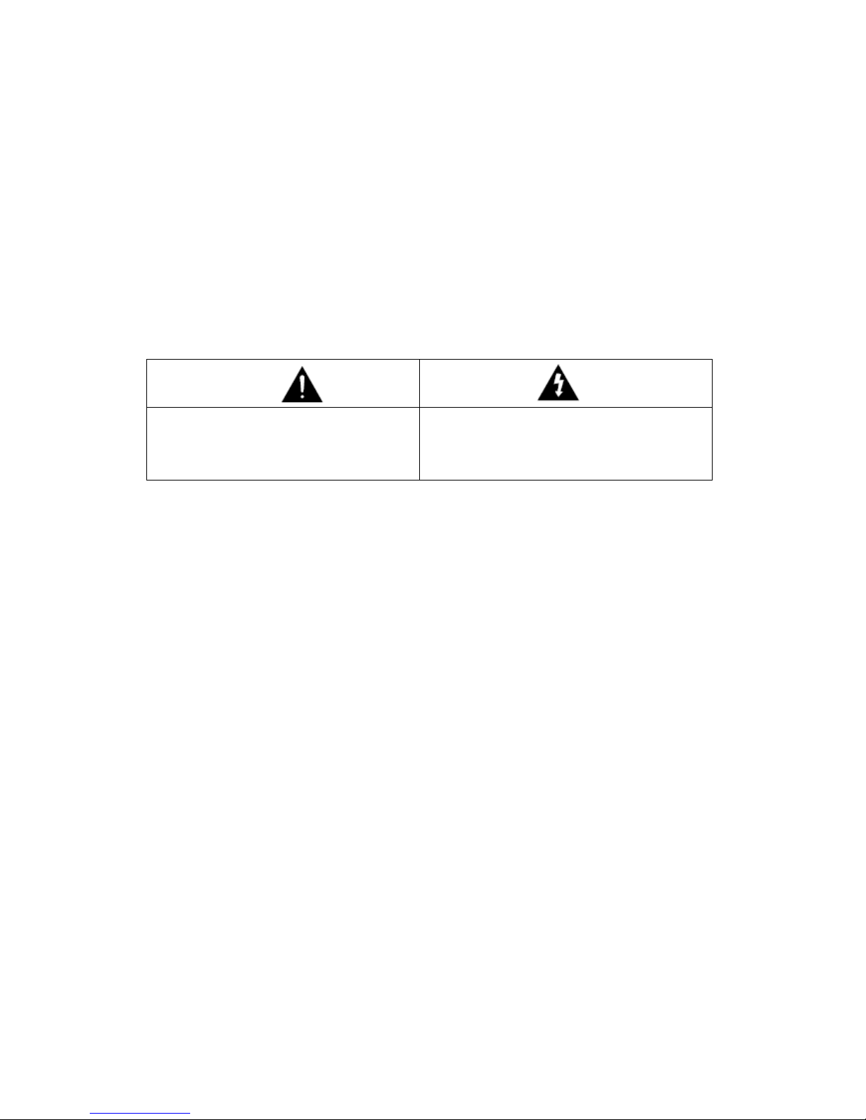
* The precautions are divided into “Warnings” and “Cautions” as distinguished
by the symbols shown below;
Warning: Ignoring these warnings may result in death or serious injury.
Caution: Ignoring these cautions may result in injury or damage to property.
Caution: Instructions alert you to the
potential risk of injury or
damage to property
Warning: Instructions alert you to
the potential risk of death
or serious injury
Warning
1. Only use the standard Raptor power adapter (Product Code RAP37-PSU)
Using any other adapter could cause fire, electrical shock, or damage to the
product.
2. Before connecting the power supply, and signal wires, make sure the external
connections are isolated. Connect the alarm signal wires to the alarm
terminals, the communication wires to the terminal block and the AC adaptor
to the AC power input receptacle (incorrectly connecting the power supply
may cause fire, electrical shock, or damage to the product).
3. Do not connect multiple cameras to a single Raptor power adapter.
Exceeding the adapter’s current capacity can cause abnormal heat generation or fire.
4. Securely plug, or connect, the power cord into the power receptacle.
An insecure or loose connection may cause a fire.
5. When installing the camera on a wall or ceiling etc. fasten it securely using
suitable anchor bolts and/or fixings.
An unsecure camera could fall and cause serious personal injury, or even a fatality.
6. Do not place conductive objects (e.g. screwdrivers, coins or other metal
objects) inside any part of the camera.
Doing so may cause personal injury, a fire or an electrical shock.

VHT Raptor Manual Ver. 3.1
6
05th June 2012
7. Do not install the unit in humid or dusty locations.
Doing so may cause a fire or electrical shock.
8. If any unusual smells or smoke come from the unit, stop using the product
immediately, disconnect the camera from the power source and contact your
distributor.
9. If this product fails to operate normally, contact your distributor.
Never disassemble or modify this product in any way.
10. Always clean the camera with water and wipe the surface dry with a soft lint
free cloth. Never use detergents or chemical agents on the product, as this
may result in discolouration of the painted surface or cause damage to the
finish.
Caution
1. Do not drop objects on the product, or apply strong shocks to it. Keep away
from locations subject to excessive vibration or magnetic interference.
2. Do not install in locations subject to a continual high temperature range (over
50°C), continual low temperature (below -40°C) or high humidity.
3. Avoid locations which are exposed to direct sunlight, radiation or near heat
sources such as heaters or radiators.
4. If an already installed product needs to be relocated, make sure the power is
turned off before it is moved.
5. Always try and install in a well-ventilated environment.
6. Make sure the camera is adequately protected against lightning strikes by
using a suitably rated surge protector, which must be locally grounded. Failure
to do so could irreparably damage the camera, and any attached
communication and telemetry equipment
VHT Raptor Manual Ver. 3.1
7
05th June 2012
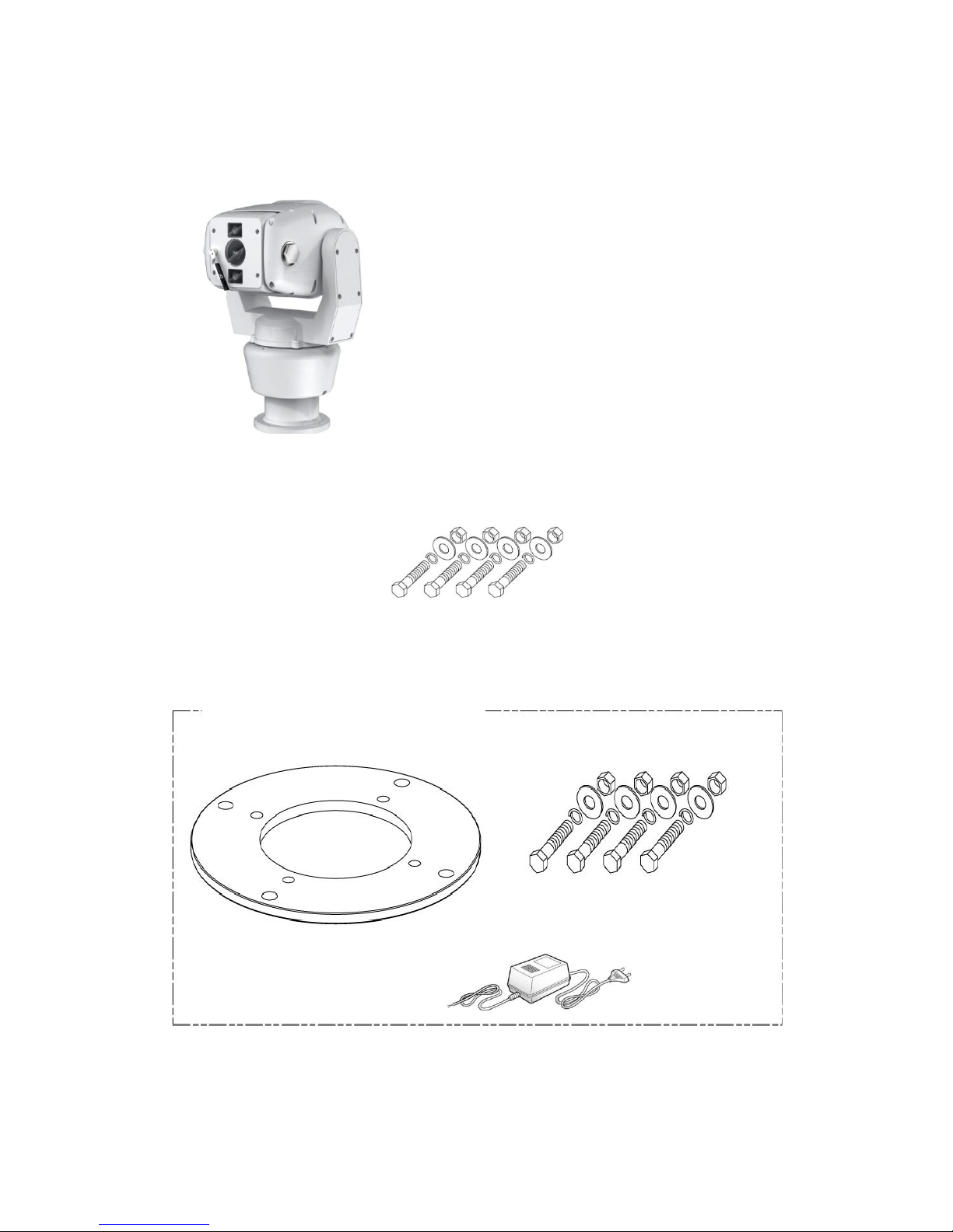
3. Packing List
Wide Dynamic X36 Zoom
Rugged PTZ Camera 1EA
Instruction Manual
1EA
Hex Bolt / Nylon Nut / Spring Washer / Plate Washer
-M8x35 (SUS) 4PCS
Option (UK_Column Mounting)
Hex Bolt / Nylon Nut / Spring Washer / Plate Washer
-M6x25 (SUS) 4PCS
Adaptor Plate
Adaptor (AC24V/3A)
VHT Raptor Manual Ver. 3.1
8
05th June 2012
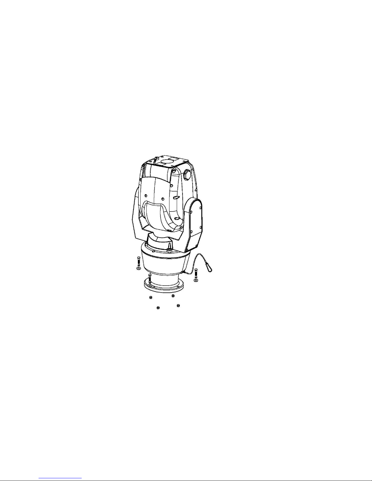
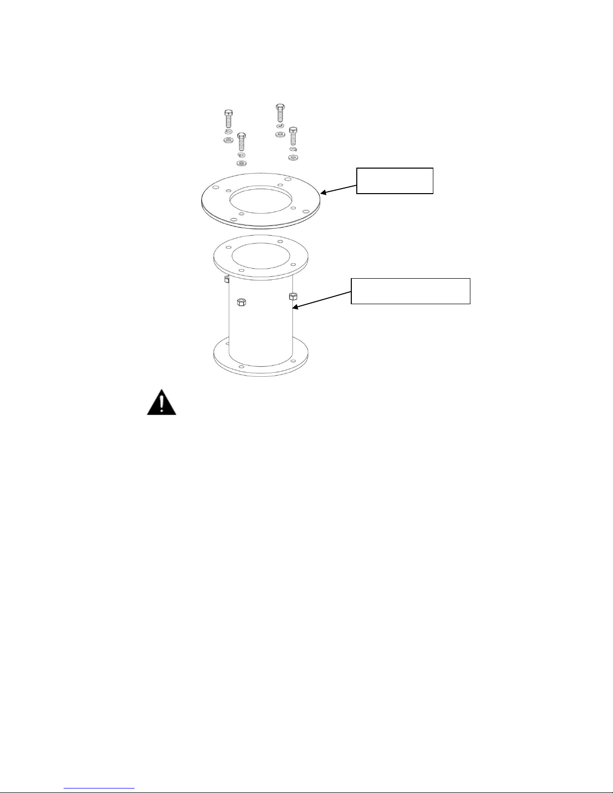
4. Mounting
This unit is designed for installation in the upright or inverted position. It is a heavy
duty mechanism and needs a secure and safe installation surface, and we
recommend installers use brackets, towers and columns which comply with the
industrial standard - 4” (142.0mm) PCD.
Cable connections are made using the camera base.
The camera base is supplied with a 4” (142.0mm) PCD adapter plate and connects to
a bracket or tower using three M8 Hex Bolts, s/w, p/w and Nylon nuts with Spring and
Plate Washers.
■ Mounting Options (UK_Column Mounting)
The camera is supplied with an adaptor, 4” (101.6mm) PCD, which complies with the
uniform standard for UK Pole or Column camera mounts.
VHT Raptor Manual Ver. 3.1
9
05th June 2012
A Safety Wire, made from stainless steel, is provided for securing
the Raptor during installation and maintenance visits to prevent
damage and injury.
During installation and maintenance visits, please be sure the
Safety Wire is firmly connected to a secure fixing.
Adaptor Plate
UK_Column Mounting
VHT Raptor Manual Ver. 3.1
10
05th June 2012
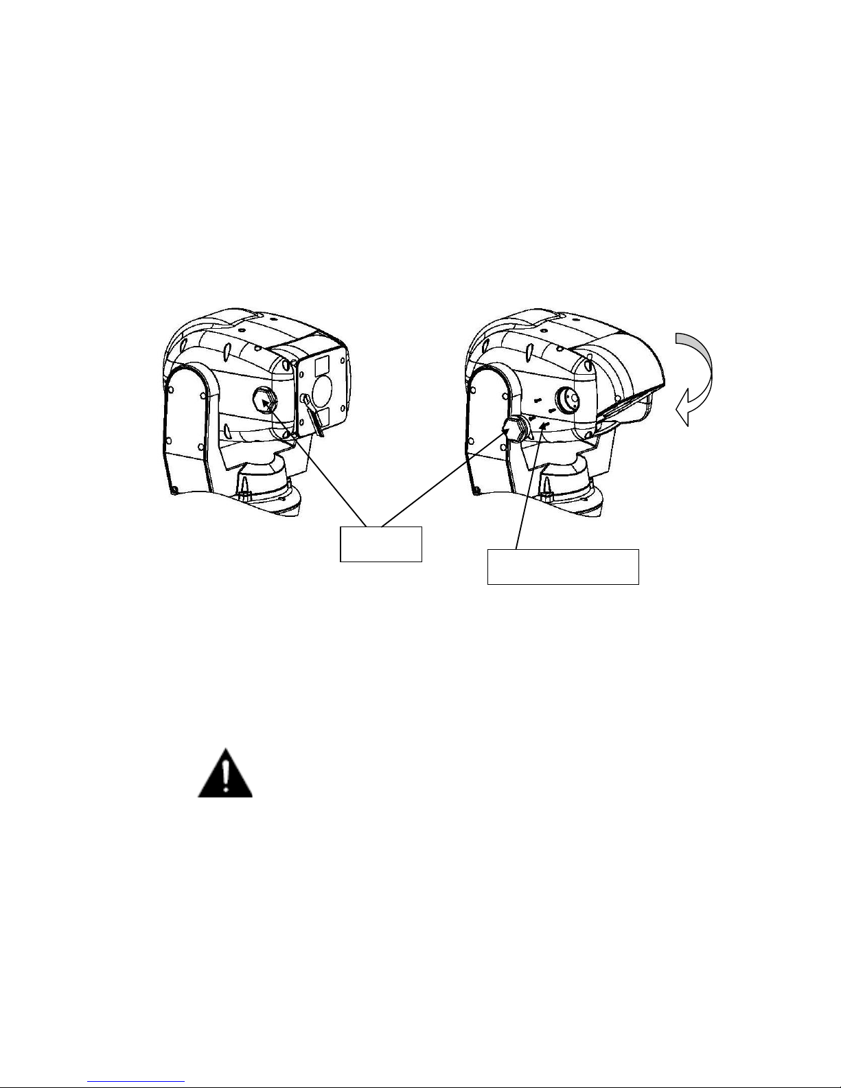
■ Offset Mounting
When an installation requires the camera module to be tilted down – to obtain an
angle of view immediately below Raptor – the following procedure should be followed.
We recommend using a local test monitor to check the viewing angle before finally
fixing the module into position.
Undo the Hex Bolt, using a 36mm Spanner, when the camera is in 0° Tilt.
Then, using a screwdriver, undo the 4 x M3 Retaining Screws.
After tilting down the camera module to the required angle replace the M3 Retaining
Screws and the Hex Bolt. The Torque setting for the Hex Bolt is 0.84Kg/m.
Do not excessively tighten the Retaining Screws or Hex Bolt.
Hex Bolt
Retaining M3 Screw
Tilt 90°
VHT Raptor Manual Ver. 3.1
11
05th June 2012
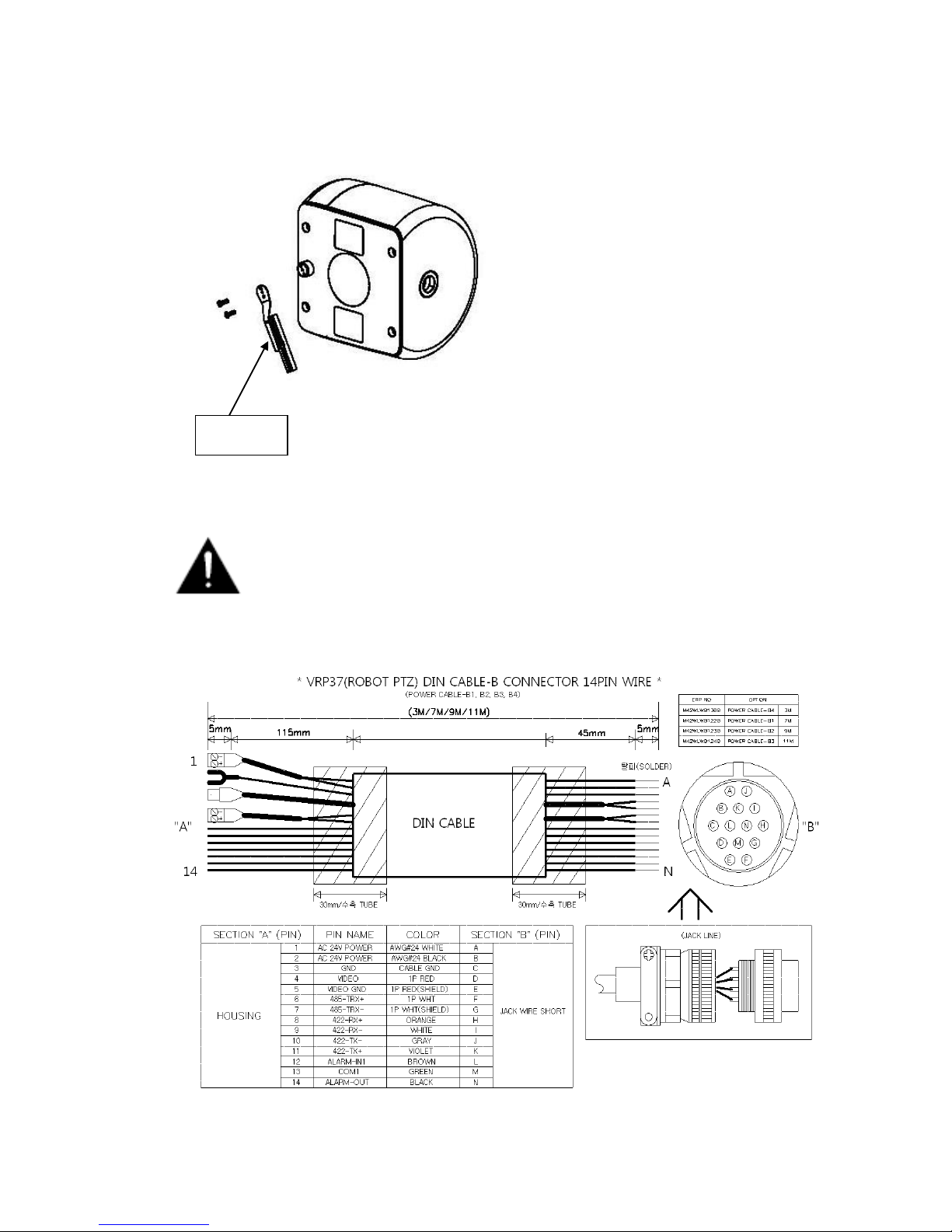
■ WIPER SET CHANGE
Change Wiper Set by undo and tighten the fixing screw.
Please keep the window clean to use a long time.
■ CABLE 14PIN CONNECTION
Wiper Set
VHT Raptor Manual Ver. 3.1
12
05th June 2012
5. Telemetry Control
This unit is designed with a range of diverse Telemetry Control systems, based on
compatibility with industrial standard protocols. It works by using these integrated
protocols directly, or via 3rd party protocol convertors.
Telemetry Control is via way of RS485 or Coaxial based video transmission
equipment. Some limitation on protocols and/or software changes may not guarantee
to take full advantage of all the features from the manufacturer, and may limit features
and operation of the Raptor.
When the Telemetry Control is based on RS485, the address range is limited to 127.
■ On-Board Protocols
This unit provides the following On-Board Protocols:
• BBV 422
• Pelco D
• Pelco P
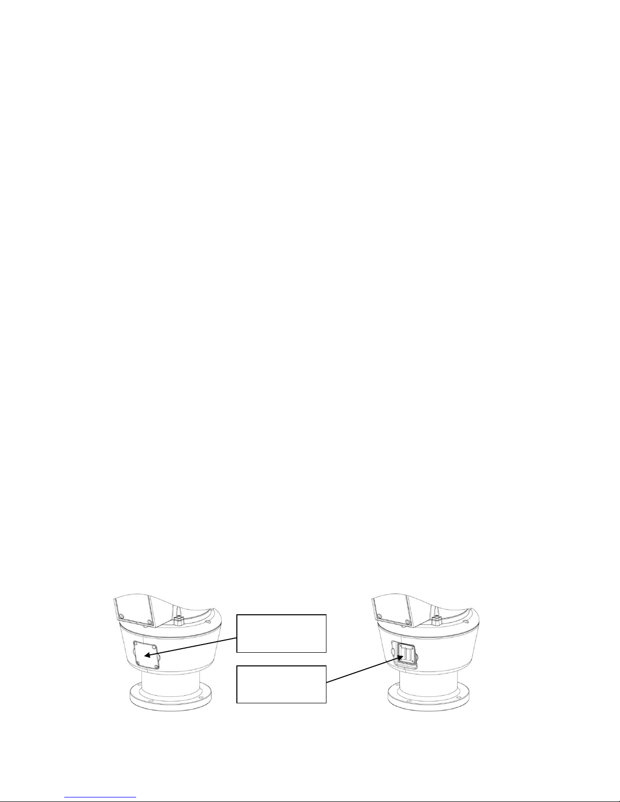
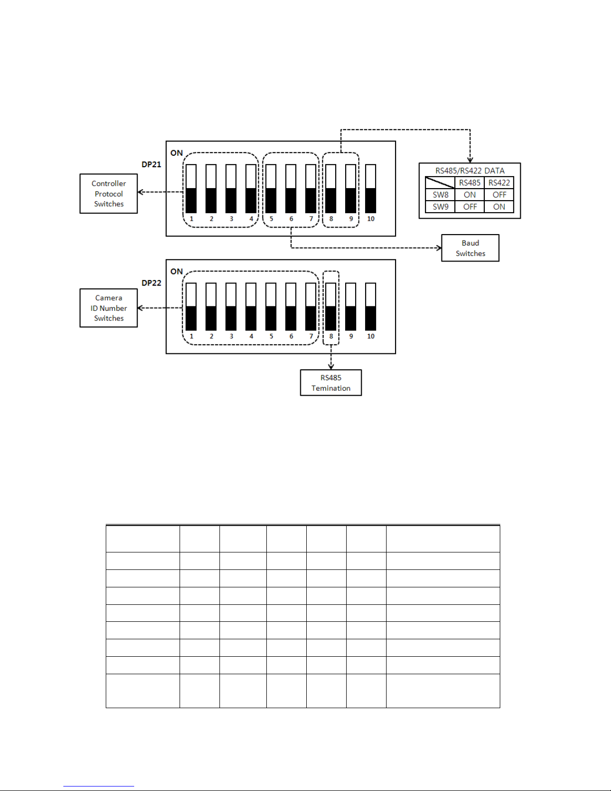
■ DIL (Dual In-Line) Switches
Two 8-way DIL Switches are contained within a waterproofed cover on the camera
body ; these are used to select camera address, communication protocol and baud
rate.
Cover retained by
four screws
Screws and cover
removed
VHT Raptor Manual Ver. 3.1
13
05th June 2012
• Protocol Settings
Protocol is selected using switches DP21-1, DP21-2, DP21-3 and DP21-4.
The configuration of the Protocol is as follows.
When an installer uses a protocol based Coaxial cable, it isn’t using a RS485 Address
so may leave Address 0.
Description
No
DP1-1
DP1-2
DP1-3
DP1-4
Apply
PELCO-D
0
OFF
OFF
OFF
OFF
OK
PELCO-P
1
ON
OFF
OFF
OFF
OK
BBV
2
OFF
ON
OFF
OFF
OK
VCL
3
ON
ON
OFF
OFF
OK
PANASONIC
4
OFF
OFF
ON
OFF
OK
AD 5 ON
OFF
ON
OFF
OK
HONEYWELL
6
OFF
ON
ON
OFF
OK
SAMSUNG
FVISION
7
8
ON
OFF
ON
OFF
ON
OFF
OFF
ON
OK
OK
VHT Raptor Manual Ver. 3.1
14
05th June 2012
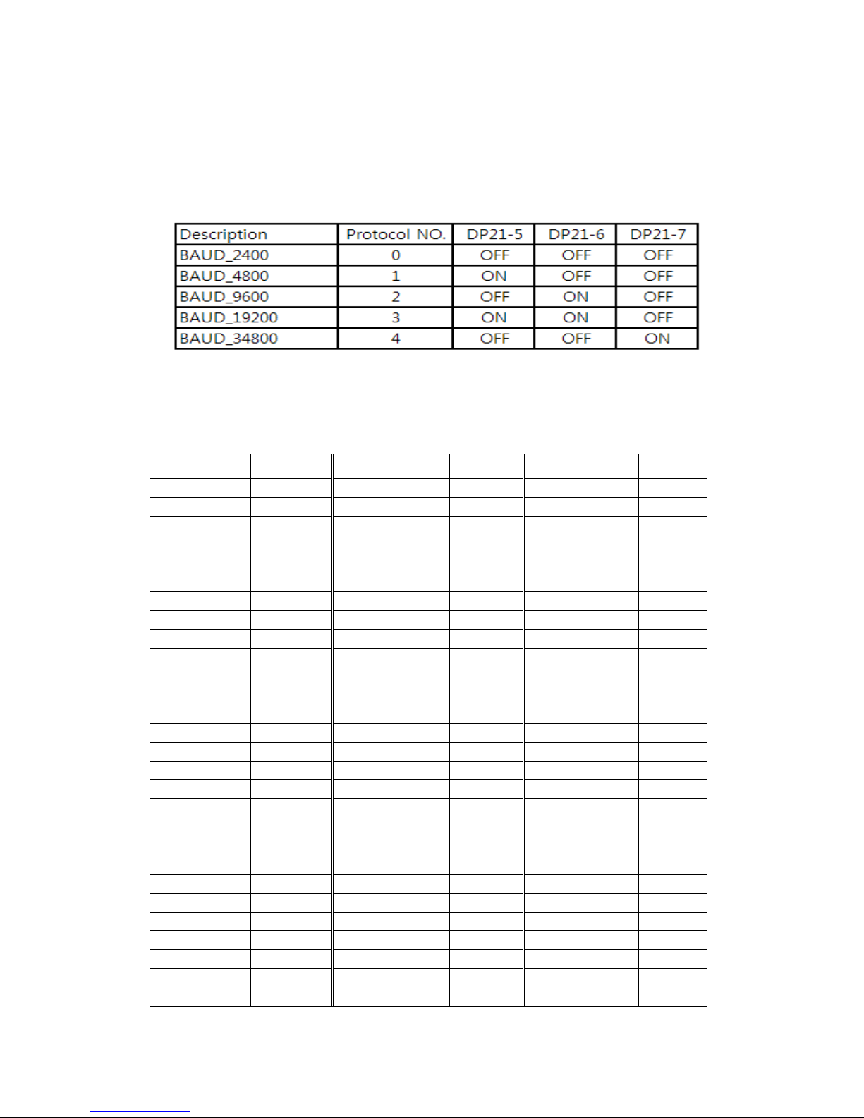
• Baud Rate Settings
The Baud Rate, communication speed, is selected using switches DP21-5, DP21-6 and DP21-
7.
Baud Rate configuration settings are as follows:
• RS485 Address Settings
ID setting for DP22 switches SW1~SW7 DIP Switch setting 1-ON, 0-OFF
DIP SW
ID
DIP SW
ID
DIP SW
ID
1000000
1
1010100
21
1001010
41
0100000
2
0110100
22
0101010
42
1100000
3
1110100
23
1101010
43
0010000
4
0001100
24
0011010
44
1010000
5
1001100
25
1011010
45
0110000
6
0101100
26
0111010
46
1110000
7
1101100
27
1111010
47
0001000
8
0011100
28
0000110
48
1001000
9
1011100
29
1000110
49
0101000
10
0111100
30
0100110
50
1101000
11
1111100
31
1100110
51
0011000
12
0000010
32
0010110
52
1011000
13
1000010
33
1010110
53
0111000
14
0100010
34
0110110
54
1111000
15
1100010
35
1110110
55
0000100
16
0010010
36
0001110
56
1000100
17
1010010
37
1001110
57
0100100
18
0110010
38
0101110
58
1100100
19
1110010
39
1101110
59
0010100
20
0001010
40
0011110
60
DIP SW
ID
DIP SW
ID
DIP SW
ID
1011110
61
0010101
84
1101011
107
0111110
62
1010101
85
0011011
108
1111110
63
0110101
86
1011011
109
0000001
64
1110101
87
0111011
110
1000001
65
0001101
88
1111011
111
1100001
67
0101101
90
1000111
113
0010001
68
1101101
91
0100111
114

VHT Raptor Manual Ver. 3.1
15
05th June 2012
1010001
69
0011101
92
1100111
115
0100001
66
1001101
89
0000111
112
0110001
70
1011101
93
0010111
116
1110001
71
0111101
94
1010111
117
0001001
72
1111101
95
0110111
118
1001001
73
0000011
96
1110111
119
0101001
74
1000011
97
0001111
120
1101001
75
0100011
98
1001111
121
0011001
76
1100011
99
0101111
122
1011001
77
0010011
100
1101111
123
0111001
78
1010011
101
0011111
124
1111001
79
0110011
102
1011111
125
0000101
80
1110011
103
0111111
126
1000101
81
0001011
104
1111111
127
0100101
82
1001011
105
1100101
83
0101011
106
• RS485 Termination
If Raptor is using RS485 communication please make sure the Bus is correctly installed and
configured to prevent malfunctions. The maximum cable distance is 1200 metres.
A Maximum of 32 units can be connected to the cable section.
Any cable type which exceeds the specification of EIA RS485 can be used. The furthest device,
by cable length, should be terminated in accordance with the specification. Other devices
should remain un-terminated.

VHT Raptor Manual Ver. 3.1
16
05th June 2012
• Keyboard Operation
Key Sequences and Joystick movements are executed to closely control the camera
and program the Telemetry Control system of Raptor. Examples of these are PRESET
and TOUR.
If a Keyboard can’t be used to access and change the camera parameters, most
characteristics are accessible through the camera’s OSD menu.
Note – Changing a Keyboard’s Software and/or Protocol can effect alterations to the
camera’s operability. The Raptor manufacturer absolves itself of responsibility for such
modifications.

VHT Raptor Manual Ver. 3.1
17
05th June 2012
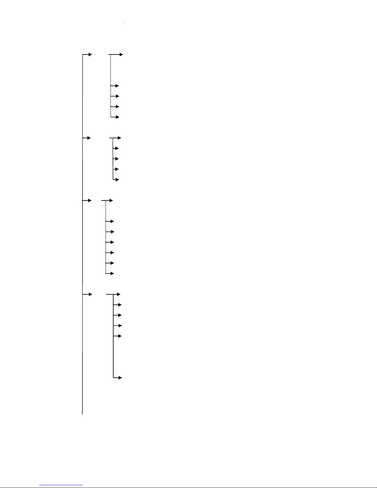
6. Setup Menu Overview
In this chapter, we will look at the overall structure of the Setup Menu and then look at the
function of each menu.
MAIN MENU
PAN/TILT ID DISPLAY → ON/OFF
SET P/T DISPLAY → OFF/ON
CAM NAME → OFF/(ON)
MANUAL SPEED → 10~110°/Sec
PROPO. P/T → ON/OFF
DIGITAL FLIP → ON/OFF
IMAGE HOLD → OFF/ON
INSTALATION → NORMAL/INVERT
AUTO REFRESH → 5~240
EXIT
CAMERA WDR WDR MODE → OFF/ON/AUTO/
SET FIX/MANUAL
SCREEN IMAGE → COMBINE/DIVIDE/
LONG/SHORT
SENSITIVITY → LOW/MID/
HIGH/XHIGH
SHADOW → LOW~XHIGH
HIGHLIGHT → LOW~XHIGH
SHORT EXP → 1~150
EXIT
MD MD DEFINE → OFF/ON
MD DISPLAY → OFF/ON
SENSITIVITY → 1~25
INTERVAL T → 1~20
AREA START H → 0~XX
AREA START V → 0~XX
AREA END H → XX~12
AREA END V → XX~8
EXIT
VHT Raptor Manual Ver. 3.1
18
05th June 2012
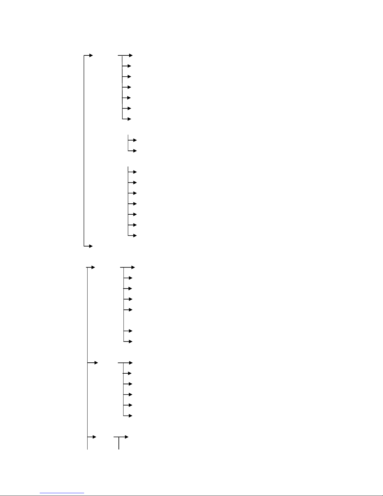
CAMERA ATW ATW MODE→ AUTO,ATW,INDOOR,
SET OUTDOOR,ONEPUSH,MANUAL,OUTAUTO,
SODIUM AUTO, SODIUM FIX
ONE PUSH TRG → <SET>
MANUAL RED → 0~200
MANUAL BLUE → 0~200
EXIT
FOCUS FOCUS MODE→ AUTO/ZOOMTG/MANUAL
/ZOOM AF SENSITIVE→NORMAL/LOW
DIG ZOOM →OFF/ON
ZOOM SPEED → 0~7
EXIT
AE AE MODE → AUTO/SHUTTER/
MANUAL
IRIS → CLOSE~F1.6
GAIN → 0~15
SHUTTER → 1/1~1/10000
SLOW SHUTTER→OFF/ON
BLC → OFF/ON
EXIT
DAY AUTO ICRMODE → OFF/ON
& NIGHT ICR MODE → DAY/NIGHT
THRESHOLD → 1dB~28dB
IR CORRECTION → OFF/ON
IR LED ANGLE → AUTO/60.0,57.0,
55.0,51.0,47.0,40.0,37.0,
33.0,28.0,23.0,20.0,15.0,
10.0,8.0,6.0,
EXIT
VHT Raptor Manual Ver. 3.1
19
05th June 2012
SPECIAL STABILIZER→ OFF/ON
AE RESPONSE → OFF/ON
IMAGE FLIP → OFF/ON
IMAGE MIRROR → OFF/ON
SHARPNESS → 0~14
NR →OFF/1~5
DE-FOG → OFF/(AUTO)/(USER)
(AUTO)
AUTO LEVEL → 1~10
EXIT
(USER)
FOG LEVEL → 0~15
FOG GAMMA → 0~15
STRENGTH → 0~64
UVSTRENTGH → 0~13
NOISESUP → 0~64
EDGE LEVEL → 0~15
EXIT
EXIT
AUTOSEQ PRESET PRESET NO → 1~128
SET PRESET DEFINE →OFF/<ON>
PRESET NAME → OFF/<ON>
POSITION → XXX/XXX
WDR → OFF/ON/AUTO/
FIX/MANUAL
ATW → <SET>
EXIT
AUTOSEQ TOUR TOUR NO → 1~5
SET TOUR NO DEF → OFF/<ON>
NAME → TOURGROUP1
TOUR NAME DEF → OFF/<ON>
DWELL TIME → 1~120
EXIT
SCAN SCAN NO → 1~5

VHT Raptor Manual Ver. 3.1
20
05th June 2012
SCAN DEFINE → OFF/ON
NAME → SCANGROUP1
SCAN NAME DEFINE→OFF/<ON>
PAN START POS→ <180>
PAN END POS → <350>
TILT POS → <45>
SCAN SPEED→2˚,5˚,10˚,20˚/S
EXIT
PATTERN PATT NUMBER → 1~2
PATT DEFINE → OFF/ON
NAME → PATTERN001
PATT NAME DEF→ OFF/<ON>
PATT RECORD → OFF/<ON>
PATT SPEED → 2˚,5˚,10˚,20˚/S
EXIT
AUTO PAN TILT ANGLE → (xxx)
PAN SPEED → 2˚,5˚,10˚,20˚/S
DIRECTION → CW/CCW
EXIT
AUTO RUN OFF/SEQ/TOUR/SCAN/PATT/A.PAN
EXIT
ZONE AREA SEL → 1~8
SET AREA DEFINE → OFF/ON
AREA COLOR → BLACK~MOSAIC
AREA NEW SET → OFF/ON
HEIGH EDIT → XXX
WIDTH EDIT → XXX
PAN ANGLE → XXX
TILT ANGLE → XXX
EXIT
ALARM ALARM DISPLAY → OFF/ON
SET ALARM IN → <SET>
ALARM OUT → OFF/ON
TIME OUT → 1~10SEC
EXIT

VHT Raptor Manual Ver. 3.1
21
05th June 2012
WIPER WIPER RUN → AUTO/<PUSH>/<RUN>/<STOP>
SET EXIT
INITIALIZE POWER ON RESET
SET PAN/TILT INIT
CAMERA INIT
AUTOSEQ INIT
PRIVACY ZONE INIT
FACTORY INIT
EXIT
System Information
The diagrams shown in the previous section illustrated the overall structure of the setup menu.
In this section, descriptions of the features within the setup menu will enable users of the
camera to tailor it to their personal needs.
MAIN MENU
1. PAN TILT SET
2. CAMERA SET
3. AUTOSEQ SET
4. ZONE SET
5. ALARM SET
6. WIPER SET
7. INITIALIZE SET
8. EXIT
1. PAN TILT SET
1. ID DISPLAY:
<ON>/OFF
2.P/T DISPLAY
ON/OFF
3.CAMERA NAME
OFF/<ON>
4. MANUAL SPEED
10~110 °/Sec
5. PROPO. P/T
ON/OFF
6. DIGITAL FLIP:
ON/ OFF

VHT Raptor Manual Ver. 3.1
22
05th June 2012
7. IMAGE HOLD
OFF/ON
8.INSTALLATION
NORMAL/INVERT
9 AUTO REFRESH
5~240
10.EXIT
Selection: UP, DOWN, LEFT, RIGHT KEY
Menu Open: IRIS OPEN KEY
Menu Close: IRIS CLOSE KEY
■ ID DISPLAY – Camera ID
OFF: The ID does not appear on the screen.
ON: The ID appears on the screen.
To change the position of the camera ID press the IRIS OPEN KEY. When ID is set to <ON>
it’s possible to move to the ID DISPLAY Menu.
■ P/T DISPLAY
Angle of PAN/TILT appears on the right side of bottom
■ CAM NAME
A maximum of 10 characters can be input. When changing the camera name, press the IRIS
OPEN Key after NAME DISPLAY is set to <ON>.
■ MANUAL SPEED
Adjustable maximum speed when PAN/ TILT are manually controlled.
■ PROPO. P/T
Automatically adjusts the PAN/TILT movement speed according to the Zoom magnification
level.
OFF � PAN/TILT movement is not automatically controlled.
ON � The PAN/ TILT speed slows down on higher zoom magnification.
■ AUTO FLIP
OFF: Operates when TILT is below 90°.
ON: Operates when TILT is over 90°.
■ IMAGE HOLD

VHT Raptor Manual Ver. 3.1
23
05th June 2012
When moving to a preset, the screen displays the frozen image of the last displayed preset
position.
OFF: Displays the current image.
ON: Displays the frozen image.
Caution - FREEZE works during a SEQ, TOUR in AUTORUN MODE.
■ AUTO REFRESH
If a PAN/TILT operation overruns its setting value AUTO REFRESH automatically
compensates.
■ INSTALLATION
NORMAL: Works when the camera is installed on the floor; like this picture.
INVERT: Works when the camera is installed on the ceiling; like this picture.
Caution – Tilt angle : Factory Default(-25~ 205 degree) ☞Tilt angle is limited at -25~90
degree after setting a zone.
1.1. I DISPLAY
ID location can be changed as follows.
1. Select <ON> from ID DISPLAY.
2. Press IRIS OPEN KEY.
MOVE: U/D/L/R
EXIT: IRISCLOSE
Selection: UP, DOWN, LEFT, RIGHT KEY
Menu Open: IRIS OPEN KEY
Menu Close: IRIS CLOSE KEY
Press IRIS CLOSE KEY when finished.
1.2 CAMERA NAME DISPLAY
CAMERA NAME: MAINCAMERA
0123456789ABCDEFGH
IJKLMNOPQRSTUVWXYZ

VHT Raptor Manual Ver. 3.1
24
05th June 2012
DELETE : <IRISOPEN>
POSITION : <IRISOPEN>
EXIT
Selection: UP, DOWN, LEFT, RIGHT KEY
Menu Open: IRIS OPEN KEY
Menu Close: IRIS CLOSE KEY
The method for naming a Camera is as follows:
1. Select DELETE and cancel MAINCAMERA by pressing the IRIS OPEN KEY.
2. Move to the desired alphanumeric and press the IRIS OPEN KEY.
3. If you want to change the location of the camera name, select POSITION and
press the IRIS OPEN KEY. The method for changing the position of the camera
name is the same as in ID DISPLAY.
2. CAMERA SET
1. WDR ---------------<SET
2. MOTION DET --------<SET>
3. ATW --------------<SET>
4. FOCUS/ZOOM ---------<SET>
5. AE ------------------<SET>
6. DAY&NIGHT ----------<SET>
7. SPECIAL -------------<SET>
8. EXIT
2. 1. WDR SETUP
1. WDR MODE
OFF~MANUAL
2.SCREEN IMAGE
COMBINE~SHORT
3. SENSITIVITY
LOW~XHIGH
4. SHADOW
LOW~XHIGH
5. HIGHLIGHT
LOW~XHIGH
6. SHORT EXP
7. EXIT
1~150
■ WDR MODE
* OFF : WDR doesn’t work

VHT Raptor Manual Ver. 3.1
25
05th June 2012
* ON : WDR is activated
* AUTO : WDR is determined automatically.
* FIX : Shutter speed in bright area is fixed. It can be applied to license plate recognition
at night.
*MANUAL : Adjust menus under WDR manually.
■ SCREEN IMAGE
* COMBINE : Select bright and dark area.
* DIVIDE : A display on screen is divided into bright and dark area.
* LONG : Display bright area.
* SHORT : Display dark area.
■ SENSITIVITY
Adjust the sensitivity from WDR OFF to ON when WDR AUTO is set.
■ SHADOW : Compensate dark area.
■ HIGH LIGHT : Compensate bright area.
■ SHORT EXP
Compensate dark area against bright area.
2.2. MOTION DETECTION
1. MD DEFINE
OFF/ON
2. MD DISPLAY :
OFF/ON
3. SENSITIVITY :
1~25
4. INTERVAL T
1~20
5. AREA START H
0~XX
6. AREA START V
0~XX
7. AREA END H
XX~12
8. AREA END V
XX~8
9. EXIT
■ MD DEFINE
When DEFINE is ON, MD is activated.
■ MD DISPLAY
If MD DISPLAY is set to ON, “MOTION” appears on the bottom right.
Motion Detection doesn’t work when the OSD MENU is activated.
■ SENSITIVITY
Sensitivity of Motion Detection is adjustable.
As the sensitivity is increased the possibility of false activations may increase.

VHT Raptor Manual Ver. 3.1
26
05th June 2012
■ INTERVAL T
MD is re-activated in accordance with setting time after Motion Derection.
■ AREA START H, AREA START V
Set a start area of Motion Detection.
■ AREA END H, AREA END V
Set an end area of Motion Detection.
Caution
1. Motion Detection doesn’t work in SCAN & PATTERN settings.
2. When using MD, the DWELL TIME should be set to a minimum of 3 seconds in TOUR
setting.
3. Do not set MD if an unstable light source is present e.g. flickering light.
4. Instant changes in light sources may cause improper working. Turning lights on or off.
5. This MD function is not intended for fire or antitheft protection and the manufacturer is free
from any responsibility should it malfunction.
2.3. ATW
1. ATW MODE:
AUTO~SODIUM FIX
2.ONE PUSH TRG
3.MANUAL RED:
<SET>
0 ~ 200
4.MANUAL BLUE:
5.EXIT
0 ~ 200
Menu Shift : UP, DOWN, LEFT, RIGHT KEY
Menu Open: IRIS OPEN KEY
Menu Close: IRIS CLOSE KEY
A White Balance setting must be specified and appropriate for the ambient lighting conditions.
■ ATW MODE AUTO
White Balance is automatically compensated when color temperature range is
3000K~7500K.
■ ATW MODE ATW
White Balance is automatically compensated when color temperature range is 2000K~10000K.
■ ATW MODE OUT DR
White Balance is optimised for an outdoor environment.
■ ATW MODE IN DR

VHT Raptor Manual Ver. 3.1
27
05th June 2012
White Balance is optimized for an indoor environment.
■ ATW MODE ONE PUSH
White Balance is optimized for the current lighting conditions. If the lighting conditions change,
the White Balance should be readjusted.
It is operated by pressing the IRIS OPEN KEY when < HOLD > is off.
■ ATW MODE MANUAL
White Balance is manually adjustable using the RED and BLUE gain controls.
■ ATW MODE OUT AUTO
White Balance is optimized for an outdoor environment in Day/Night
■ ATW MODE SODIUM AUTO
White Balance is automatically compensated for the strong lighting conditions like the sodium
lamp
■ ATW MODE SODIUM FIX
White Balance is optimized for the sodium lamp
2.4. FOCUS/ZOOM
1. FOUCS MODE:
AUTO/ZOOM/MANUAL
2. AF SENSITIVE:
NORMAL/LOW
3. DIG ZOOM:
OFF/ON
4. ZOOM SPEED:
1~7
5. EXIT
■ FOCUS MODE
* AUTO
FOCUS is adjusted automatically.
* MANUAL
FOCUS is adjustable manually.
* ZOOMTRG
Whenever ZOOM is changed, the FOCUS also changes.
■ AF SENSITIVE
* NORMAL
Focus is adjusted fast automatically.
* LOW
More effective in low light environments.
■ DIG ZOOM
Digital Zoom activate at the Maximum level of optical zoom, if user keep pushing “Tele”

VHT Raptor Manual Ver. 3.1
28
05th June 2012
button.
■ ZOOM SPEED
Adjust the zoom tracking speed.
2.5. AE
1. AE MODE:
AUTO/SHUTTER/
MANUAL
2. IRIS:
CLOSE~F1.6
3. GAIN:
0~15
4. SHUTTER:
1/1~1/10000
5. SLOW SHUTTER:
OFF/ON
6.BLC:
OFF/ON
7. EXIT
■ AE MODE
* AUTO
IRIS and GAIN are Controlled automatically. Shutter speed is fixed at 1/60sec(NTSC) or
1/50sec(PAL).
* SHUTTER
IRIS and GAIN are Controlled automatically. Shutter speed can be adjusted manually.
In order to suppress a FLICKER, user can set a shutter speed at 1/100sec(PAL) or
1/120sec(PAL).
* MANUAL
User can control IRIS, GAIN and SHUTTER manually.
■ SHUTTER
When capturing fast moving subjects, or under low light conditions, users can adjust the
shutter speed up or down to get improved images.
■ SLOW SHUTTER
When AE MODE is AUTO and the brightness is decreased, Shutter speed is set
automatically
*OFF (AUTO)
Under low light conditions, shutter speed is automatically controlled according to the
brightness of the scene.
*ON (MANUAL)
Under low light conditions, shutter speed is controlled according to set point.

VHT Raptor Manual Ver. 3.1
29
05th June 2012
Caution
SLOW SHUTTER SPEED OFF doesn’t work when WD MODE is ON.
■ BLC
If the subject shows dark against a bright background, this function is useful.
2.6. DAY&NIGHT
1. AUTO ICRMODE:
OFF/ON
2. ICR MODE:
DAY/NIGHT
3. THRESHOLD:
1dB ~ 28Db
4. IR CORRECTION:
OFF/ON
5.IR LED ANGLE:
6. EXIT
AUTO/60.0~6.0
■ AUTO ICRMODE
OFF Turn to Color mode or B/W mode according to set point on ICRMODE.
ON Turn to Color mode during daytime and B/W mode at night automatically.
■ ICR MODE
DAY Turn to Color mode.
NIGHT Turn to B/W mode.
■ THRESHOLD
Set the switching time from B/W mode to Color mode.
■ IR CORRECTION
OFF Set “OFF” when user do not use IR
ON Set “ON” when B/W mode and IR is activated to get a clear image.
Caution
Please set “ON” when IR is activated.
■ IR LED ANGLE
AUTO IR LED ANGLE is controlled automatically according to ZOOM ratio.
60.0 IR LED ANGLE is fixed at 60.0 degree.
6.0 IR LED ANGEL is fixed at 6.0 degree. Useful to monitor the object far in the distance
more than 30M.
Caution
If users set IR LED ANGLE at 60.0~6.0, IR LED ANGLE is fixed at set point when AUTO
RUN is working.

VHT Raptor Manual Ver. 3.1
30
05th June 2012
2.7. SPECIAL
1. STABLIZER:
OFF/ON
2. AE RESPONSE:
1~32
3. IMAGE FLIP:
OFF/ON
4. IMAGE MIRROR:
OFF/ON
5. SHARPNESS:
6. NR
7. DE-FOG
8. EXIT
0~14
OFF/1~5
OFF/AUTO/<USER>
■ STABLIZER
ON Set “ON” to mitigate the video vibrations when the camera is in an unstable
environment, such as mounted on a pole which is subject to wind movement.
■ AE RESPONSE
Response time of AUTO EXPOSURE is adjustable.
Caution
If set the value of AE RESPONSE excessively, AUTO EXPOSURE could operate late.
■ IMAGE FLIP
The screen flips horizontally.
■ IMAGE MIRROR
The screen flips vertically.
■ SHARPNESS
Overall sharpness on the screen is adjustable.
■ NR(Noise Reduction)
Reduce Image noise in low light condition.
■ DE-FOG
OFF : Disable DE-FOG.
AUTO: Automatic start DE-FOG.
USER : USER Setting.

VHT Raptor Manual Ver. 3.1
31
05th June 2012
2.7.1 DEFOG AUTO SETUP
1. AUTO LEVEL
0~10
2. EXIT
If set higher value of AUTO LEVEL, DEFOG function will be sensitive.
2.7.1 DEFOG USER SETUP
1. FOG LEVEL
0~15
2. FOG GAMMA
0~15
3. STRENGTH
0~64
4. UV STRENGTH
0~13
5. NOISE SUP
6. EDGE LEVEL
7. EXIT
0~64
0~15
■ FOG LEVEL Fog Density.
■ FOG GAMMA The adjustable numeric value for contrast level control.
■ STRENGTH If this value is high, bright parts of the image get darker and
dark parts get brighter.
■ UV STRENGTH Only use if the STRENGTH option is set - adjusts the colour
level.
■ NOISE_SUP Decrease noise in low illumination.
■ EDGE LEVEL Improve image definition.
Caution
1. If DE-FOG is set to “AUTO” and the camera switches to B/W mode DE-FOG changes
to OFF.
2. In “Manual” if the camera switches to B/W mode DE-FOG stays in the ON state.
3. AUTOSEQ SET
1. PRESET
<SET>
2. TOUR
<SET>
3. SCAN
<SET>
4. PATTERN
<SET>
5. AUTO PAN
<SET>

VHT Raptor Manual Ver. 3.1
32
05th June 2012
6. AUTO RUN
7. HOME POSITION
8. EXIT
OFF/SEQ/TOUR/SCAN/PATT/PAN
OFF/1~128
Menu Shift: UP, DOWN, LEFT, RIGHT KEY
Menu Open: IRIS OPEN KEY
Menu Close: IRIS CLOSE KEY
PRESET Location of the PAN/TILT and ZOOM can be programmed. In an ALARM or TOUR
operation, the camera moves to the programmed preset.
SEQ The programmed PRESET is executed from the lowest order, sequentially.
TOUR PRESET works in GROUP. Up to 5 presets per group can be registered and up to 5
groups can be operated.
SCAN PAN moves from the start point to the end point and up to 5 scans can be set up.
PATTERN The operational path of PAN/TILT actions is saved and PATTERN plays and
repeats these PAN/TITL actions.
AUTO PAN Continually PAN’s.
■ AUTORUN
OFF The camera is in a Standby condition.
SEQ, TOUR, SCAN, PATT, A.PAN Are executed automatically after the user exits the OSD
MENU.
■ HOMEPOSITION
If there is any loss of power the camera goes to the programmed Preset.
Caution
If AUTORUN is set the camera does not go to the programmed Preset.
3.1. PRESET
This function moves to a designated position after the user selects the desired target and
location.
1. PRESET NO:
1~128
2. PRESET DEFINE:
OFF/<ON>
3. PRESET NAME:
OFF/<ON>
4. P/T POSITION:
P/T ANGLE
5. WDR:
OFF/ON/AUO/FIX/MANUAL

VHT Raptor Manual Ver. 3.1
33
05th June 2012
6. ATW:
<SET>
7. EXIT
Menu Shift: UP, DOWN, LEFT, RIGHT KEY
Menu Open: IRIS OPEN KEY
Menu Close: IRIS CLOSE KEY
■ PRESET NO
A total of 128 presets can be set up.
Changing the PRESET NO is achieved by using the LEFT and RIGHT KEY.
■ PRESET DEFINE
OFF PRESET doesn’t work
ON Applicable PRESET is useable.
Location change of PAN/TILT/ZOOM in PRESET is as follows.
1. After PRESET DEFINE is changed from OFF to ON, press the IRIS OPEN KEY
2. Use PAN and TILT to move to the desired location.
PREST NAME: PRESET0001
PAN: XXX
TILT: XXX
ZOOM: T/W EXIT: IRIS CLOSE
3. If the user wants to ZOOM in on the location, use the TELE or WIDE button on the controller.
4. Finalise the PAN, TILT and ZOOM settings by pressing the IRIS CLOSE KEY.
■ PRESET NAME
OFF When using a PRESET, the PRESET name is not displayed on the screen.
<ON> When using a PRESET, the PRESET name is displayed on the screen.
Default for PRESET name is PRESET0001 and the editing method is as follows:
1. After changing a PRESET NAME from OFF to <ON> press the IRIS OPEN KEY.
2. Editing a PRESET NAME is the same as shown in section “1.3 CAMERA NAME DISPLAY”.
■ WDR
Lessen contrast between dark and bright areas.
■ ATW
The White Balance setting for the current PRESET is selectable. It is set as follows:
1. Select ATW menu
2. Press the IRIS OPEN KEY in <SET>.
3. The method for setting ATW is the same as shown in section “2.3. ATW”.

VHT Raptor Manual Ver. 3.1
34
05th June 2012
<Caution>
When setting a PRESET and TILT is over 90°, PAN/TILT automatically moves to the position
-20°~90° and TILT is limited to 90°.
3.2. TOUR
This function makes the camera repeatedly follow a series of pre-programmed presets.
1. TOUR NO:
1 ~ 5
2. TOUR NO DEF:
OFF/<ON>
3. NAME:
TOURGROUP1
4. TOUR NAME DEF:
OFF/<ON>
6. DWELL TIME:
7. EXIT
1~120
■ TOUR NO
A maximum of 5 groups can be registered.
■ TOUR NO DEF
OFF TOUR Group setting is cancelled.
ON TOUR is set up.
<Setting example>
TOUR NO
1 2 3 4 5
TOUR DEF
ON
OFF
ON
OFF
ON
TOUR will be executed in programmed preset 1, 3 & 5.
The method for setting TOUR GROUP 1 in PRESET is as follows:
1. Register “1” as a TOUR NO.
2. Change the status of TOUR NO DEF from OFF to <ON> and press the IRIS OPEN KEY.
1. PRESET NUMBER
OFF/1~128
2. PRESET NUMBER
OFF/1~128
3. PRESET NUMBER
OFF/1~128
4. PRESET NUMBER
OFF/1~128
5. PRESET NUMBER
6. EXIT
OFF/1~128
3. Input the desired PRESET number from 1 onward in sequential order.

VHT Raptor Manual Ver. 3.1
35
05th June 2012
4. Press the IRIS CLOSE KEY to finalise the setting.
■ NAME
Changing the name of a TOUR GROUP.
The method for changing the name is as follows:
1. After changing TOUR NAME DEF from OFF to <ON>, press the IRIS OPEN KEY.
2. Changing a Tour Group name uses the same method shown in “1.3 CAMERA NAME
DISPLAY”.
■ DWELL TIME
Is the waiting time between PRESET execution and moving to the next PRESET.
<Caution>
1. If TOUR GOURP1 PRESET is set up as follows.
1. PRESET NUMBER
1
2. PRESET NUMBER
2
3. PRESET NUMBER
3
4. PRESET NUMBER
OFF
5. PRESET NUMBER
6. EXIT
4
After moving through PRESET1 > PRESET2 > PRESET3, the camera returns to PRESET1.
If any PRESET is “OFF” during an operation in serial order, the camera returns to the first
preset.
3.3. SCAN
This function automatically moves the camera back and forth from one point to another.
1. SCAN NO
1 ~ 5
2. SCAN DEFINE
OFF/ON
3. NAME
SCANGROUP1
4. SCAN NAME DEF
OFF/<ON>
5.PANSTART POS
<180>
6. PAN END POS
<350>
7. TILT POS
<45>
8. SCAN SPEED
9. EXIT
2°, 5°,10°,20°/S

VHT Raptor Manual Ver. 3.1
36
05th June 2012
■ SCAN NO
A maximum of 5 Scans can be registered.
■ SCAN NO DEF
OFF SCAN is cancelled
ON SCAN can be set up (it should be “ON” for operation in AUTO RUN)
<Setting example>
SCAN NO
1 2 3 4 5
SCAN DEF
ON
OFF
ON
OFF
ON
SCAN will be executed in programmed preset 1,3 &5.
The method for setting up SCAN1 in PRESET is as follows:
1. Register “1” as the SCAN NO.
2. Change SCAN DEFINE from OFF to <ON> and press the IRIS OPEN KEY.
■ NAME
This changes the SCAN Name.
The method for changing the SCAN NAME is as follows:
1. Change SCAN NAME DEF from OFF to <ON> and press the IRIS OPEN KEY.
2. The method for changing the SCAN name is the same as for “1.3 CAMERA NAME
DISPLAY”.
■ PAN START POS
This sets up the initial location for the SCAN.
The method for setting up a SCAN is as follows:
1. Press the IRIS OPEN KEY in PAN START POS.
PAN START POSITION SET
PAN START POSITION: XXX
EXIT: IRIS CLOSE
PAN Shift: LEFT, RIGHT KEY
2. After moving to the desired position, press the IRIS OPEN KEY.
■ PAN END POS
This sets up the finish location for the SCAN.
The method for setting up PAN END POS is the same as for “PAN START POS”.
■ TILT POS
This sets up the TILT angle in the SCAN.
Set up is similar to “PAN START POS” but the UP, DOWN KEY should be used.
■ SCAN SPEED
Sets up the SCAN Speed.

VHT Raptor Manual Ver. 3.1
37
05th June 2012
The speed can be set between 2°/sec (slow) ~ 20°/sec (fast).
<Caution >
1. The values applied for WDR and ATW are those set on the OSD.
2. Set up angle of the initial and finish location for the SCAN should not be over 180°.
3. Use AUTOPAN(A.PAN) for Continually PAN’s in SCAN.
4. If set a SCAN at TILT over 90°, PAN/TILT automatically moves to the position -20°~90° and
TILT is limited to 90°.
3.4. PATTERN
A PATTERN is a memorised pre-programmed joystick path.
1. PATT NUMBER
1 ~ 2
2. PATT DEFINE
OFF/ON
3.NAME
PATTERN001
4.PATTNAME DEF
OFF/<ON>
5.PATT RECORD
OFF/<ON>
6. PATT SPEED
7. EXIT
2°,5,10,20°/S
MENU Shift: UP, DOWN, LEFT, RIGHT KEY
MENU Open: IRIS OPEN KEY
MENU Close: IRIS CLOSE KEY
■ PATT DEFINE
OFF: PATTERN is cancelled
ON: PATTERN is set up.
If operating in AUTO RUN, PATT DEFINE should to be set to ON.
■ NAME
Changes the PATTERN Name.
The method for setting up PATTERN NAME is as follows:
1. Change PATTERN NAME DEF from OFF to <ON> and press the IRIS OPEN KEY.
2. Changing the name uses the same method as shown in “1.3CAMERA NAME DISPLAY”.
■ PATT RECORD
OFF: PATTERN is not memorised.
ON: PATTERN is memorised.
How to set up a PATTERN
1. Change PATT RECORD from OFF to <ON> and press IRIS OPEN KEY.

VHT Raptor Manual Ver. 3.1
38
05th June 2012
MEMORY FILL: XXX ( Recorded )
START:IRIS OPEN
EXIT:IRIS CLOSE
PAN/TILT Shift: UP, DOWN, LEFT, RIGHT
2. Move PAN/TILT to the desired position before starting PATTERN.
3. Press IRIS OPEN KEY to start the process
4. Press IRIS CLOSE to save the process.
<Caution >
1. If there is no PAN/TILT movement, no PATTERN is memorised.
2. The values applied for WDR and ATW are those set on the OSD.
3. If set a PATTEREN at TILT angle over 90°, PAN/TILT automatically moves to the position -
20°~90° and TILT is limited to 90°.
3.5. AUTO PAN
Pan is rotate 360° according to setting value of TILT ANGLE, DIRECTION and SPEED.
1. TILT ANGLE:
<XXX>
2. PAN SPEED:
3. DIRECTION
EXIT
2°,5°,10°,20°/S
CW/CCW
■ TILT ANGLE
Move to TILT ANGLE and Press MANU KEY. For FINISH, Press MANU KEY.
<Caution >
1. Zoom is automatically switched to 1X.
2. WDR, ATW are set to FACTORY DEFAULT.
3. If set an AUTO PAN at TILT over 90°, PAN/TILT automatically moves to the position 20°~90° and TILT is limited to 90°.
4. ZONE SET

VHT Raptor Manual Ver. 3.1
39
05th June 2012
1.AREA SEL
1 ~ 8
2.AREA DEFINE
3.AREA COLOR
OFF/ON
BLACK!MOSAIC
3.AREA NEW SET
OFF/ON
5.HEIGHT EDIT
XXX
6.WIDTH EDIT
XXX
7.PAN ANGLE
XXX
8.TILT ANGLE
9.EXIT
XXX
MENU Shift: UP, DOWN, LEFT, RIGHT KEY
MENU Open: IRIS OPEN KEY
MENU Close: IRIS CLOSE KEY
For protection of Privacy, set MOSAIC ZONE
■ AREA SEL
Up to 8 PRIVACY ZONES can be set up.
■ AREA DEFINE
OFF: PRIVACY ZONE is not activated.
ON: PRIVACY ZONE is activated.
■ AREA COLOR
Color of MOSAIC ZONE is selectable.
■ AREA NEW SET
OFF: Previous PRVIACY ZONE is activated.
ON: New PRIVACY ZONE is set up from the current PAN/TILT position.
(when switching from OFF to ON the PRIVACY ZONE appears in the centre on the screen)
■ HEIGHT EDIT
Adjust the height of ZONE.
■ HEIGHT EDIT
Adjust the width of ZONE.
■ PAN ANGLE
Move a setting ZONE from side to side.
■ PAN ANGLE
Move a setting ZONE from up and down.
How to set up PRIVACY ZONE 1
1. When the MENU is OFF, locate the PRIVACY ZONE block in the centre on the screen by

VHT Raptor Manual Ver. 3.1
40
05th June 2012
using PAN/TILT function.
2. Press the IRIS OPEN KEY to activate MENU and move to “ZONE SET”. And then, press
the IRIS OPEN KEY again.
3. Change AREA SEL to 1.
4. Change AREA DEFINE from OFF to ON.
5. Change AREA NEW SET from OFF to ON.
6. New ZONE is activated in the centre of the screen and the ZONE can be moved using the
HEIGHT, WIDTH, PAN and TILT Menu.
7. Press the IRIS CLOSE KEY to finalise the set up.
<Caution >
Please set a MASK within -20°~80° of TILT angle.
If set a MASK at TILT angle over 90°, PAN/TILT automatically moves to the position within 90°.
5.ALARM SET
1. ALARM DISPLAY
OFF/ON
2. ALARM IN
3. ALARM OUT
<SET>
OFF/ON
4. TIME OUT
1~10sec
5.EXIT
■ ALARM DISPLAY
When signals are input from outside, the alarm number is displayed on the monitor.
■ ALARM IN
Move to the PRESET by detection of ALARM INPUT from external sensor.
How to set up PRESET
1. Move to ALARM IN, Press IRIS OPEN KEY. Below menu will follow.
1. IN1 PRESET NUM
OFF/1~128
2. EXIT
2. Set a PRESET number.
3. Move to EXIT and Press RIGHT KEY to finalise the set up.
■ TIME OUT
Set a TIME OUT for waiting time from PRESET to reactivation of TOUR after ALARM IN.
<Caution >
1. PRESET DEFINE should be set to “ON” to activate “ALARM IN”
2. A ground of external alarm signal should be maintained at least 200ms.

VHT Raptor Manual Ver. 3.1
41
05th June 2012
6.WIPER SET
AUTO : WIPER is activated at TILT angle within 80°~100°.
PUSH : WIPER is activated one time.
RUN : WIPER ON
OFF : WIDET OFF
Select menu by using Joystick and Press IRIS OPEN to activation.
7. INITIALIZE SET
1. PRESET(REBOOT)
2. PAN/TILT INIT
3. CAMERA INIT
4. AUTO SEQ INIT
5.PRIVACY ZONE INIT
6. FACTORY INIT
7.EXIT
MENU Shift: UP, DOWN
MENU Open: IRIS OPEN KEY
MENU Close: IRIS CLOSE KEY
■ POWER ON RESET
The unit is initialised.
■ PAN/TILT INIT
1. PAN/TILT MENU is initialised.
2. PAN/TILT location is initialized.
■ CAMERA INIT
Only the CAMERA setting menu is initialised.
■ AUTO SEQ INIT
1. Only the AUTO SEQ menu is initialised.
2. PRESET information and PATTERN memory are not initialised.
■ PRIVACY ZONE INIT
PRIVACY ZONE is initialised.
■ FACTORY INIT
All Menu set ups are reset to factory default.

VHT Raptor Manual Ver. 3.1
42
05th June 2012
WTX-1200A – Simple PRESET Setting
The following keyboard controller commands work when the OSD MENU is not activated.
How to set up a PRESET
1. Move the camera to the desired PAN/TILT/ZOOM location using the Joystick.
2. Press No. 1 on the keyboard
3. Press and hold the F1 Key until “SETTED” appears in the bottom right on the screen.
<Caution>
When using the shortcut key to set PRESETS, they can be in the range 1-64. With regard to
PRESETS of 65 and over, these should be set up using the OSD Menu.
WTX-1200A – Simple PRESET Shift
Press the PRESET number followed by the F1 key and the camera moves to the
corresponding PRESET position. However, this is only valid up to PRESET no. 32 for which
PRESET DEFINE is set to ON.

VHT Raptor Manual Ver. 3.1
43
05th June 2012
WTX-1200A - Simple TOUR Operation
Press number 71on the keypad followed by the F1 key. This works when TOUR DEFINE is ON
and the TOUR related MENU is properly set up.
WTX-1200A- Simple PATTERN Operation
Press number 66 on the keypad followed by the F1 key. This works when PATTERN DEFINE is
ON and the PATTERN related MENU is properly set up.
WTX-1200A - Simple SCAN Operation
Press number 81 on the keypad followed by the F1 key. This works when SCAN DEFINE is ON
and the SCAN related MENU is properly set up.
WTX-1200A - Simple Sequence Operation
Press the F1 key shortly after pressing keypad 70. This works when PRESET is set up.
Quick Operation Key Table
[PELCO D /P PROTOCOLS]

VHT Raptor Manual Ver. 3.1
44
05th June 2012
Number
Function
1~64+Preset
Setting Preset
Press Preset button for more than 2
seconds.
1~64+Preset
Executing Preset
65+Preset
Executing A.PAN
66+Preset
Executing Scan
70+Preset
Executing Sequency
71+Preset
Executing Tour
81+Preset
Executing Pattern
84+Preset
Wiper Run
86+Preset
Wiper (1 time operation)
80+Preset
Wiper Stop
95+Preset
IRIS OPEN (OSD Menu)
96+Preset
IRIS CLOSE
* How to operate MAIN MENU
95+GO PRESET(MENU KEY)
* How to operate SUB MENU
95+ GO PRESET(MENU KEY) or Press IRIS OPEN
* How to operate MAIN EXIT
1. Move to “EXIT” and Press MENU KEY or IRIS OPEN .
2. Press IRIS CLOSE or 96+GO PRESET
SPECIFICATIONS
VIDEO
CCD SENSOR
1/4” EX-view HAD CCD
Effective Pixel
NTSC : 380,000,PAL:440,000
H. Resolution
550TVL
Auto Iris type
DC IRIS
Lens
3.4~122.4mm36x
OpticalZoom
Focus System
Automatic
S/N Ratio
More than 50dB(Weight ON)
M.Illumination
0Lux

VHT Raptor Manual Ver. 3.1
45
05th June 2012
IR Distance
100M
Pan/Tilt
PAN 360°,Tilt 25°~205°
OSD/DSP
Digital Zoom
OFF/2x/4x/8x/10x/12x
Day & Night
Color/BW/Auto(ICR)
BLC
ON/OFF
WDR
ON/OFF
Shutter Speed
Auto/Manual(1/3~1/10000sec)
White Balance
Auto/ATW/Indoor/Outdoor
One Push/Outdoor Auto
Video Gain
Control
0~15 Level
Noise Reduction
OFF/1~5
Privacy Zone
ON/OFF(8programmable
zone)
Presets
255 Programmable
Digital Flip
ON/OFF
Focus control
Auto/ZOOMMTG/Manual
Wipe
Auto/Push/Run
IR Angle
6°~60°
Motion Detection
ON/OFF
DIS
Yes
Connetors/Switchs/Mechanical
Video OUT
BNCx1,1.0Vpp,75Ω,Composite
Alarm Input
3
Alarm Ouput
1
RS485
Pelco D/P & other protocals
Other
Environment
IP68
Power
24VAC 60W@Heater/Blower
Operating Temp.
-40℉~122℉
Dimension
200x469mm(DiameterxHeight)
Weight
13.5Kg

VHT Raptor Manual Ver. 3.1
46
05th June 2012
Dimension (mm)

VHT Raptor Manual Ver. 3.1
47
05th June 2012

VHT Raptor Manual Ver. 3.1
48
05th June 2012
Vision Bldg. 150-3 Simgok-dong, Wonmi-gu, Bucheon-si, Gyeonggi-do, 420-010 Korea Tel:
+82-32-610-7800 Fax: +82-32-668-3113 Mail: vht@visionhitech.co.kr
www.visionhitech.co.kr www.visionipvideo.com
 Loading...