

Page 1

Page 2

Table of Contents
Chapter 1 - Introduction ................................................................................................................................2
1.1 - Before Use ......................................................................................................................................... 2
1.2 - Specifications ..................................................................................................................................... 2
1.3 - Opening the Package......................................................................................................................... 3
1.4 - Installation.......................................................................................................................................... 3
1.4.1 - Image Sticking............................................................................................................................ 3
1.5 - Important Safety Guidelines............................................................................................................... 4
1.6 - Television Antenna Connection Protection ........................................................................................ 5
1.7 - Package Contents.............................................................................................................................. 6
1.8 - Front Panel Controls .......................................................................................................................... 7
1.9 - Rear Panel Connections .................................................................................................................... 8
1.10 - VIZIO Universal Remote Control...................................................................................................... 9
1.10.1 - Key Remote Control Functions................................................................................................10
1.10.2 - Insertion of Batteries in the Remote Control............................................................................12
1.10.3 - Remote Control Range............................................................................................................13
1.10.4 - Precautions for the VIZIO Universal Remote Control ..............................................................13
Chapter 2 - Connecting Components.........................................................................................................14
2.1 - Which Video Connection Should I Use? ...........................................................................................14
2.2 - Connecting Your DVD Player............................................................................................................15
2.2.1 - Using Digital Video ....................................................................................................................15
2.2.2 - Using Component Video ...........................................................................................................16
2.2.3 - Using S-Video ...........................................................................................................................17
2.2.4 - Using Composite Video.............................................................................................................18
2.3 - Connecting Your HDTV Set-Top Box................................................................................................19
2.3.1 - Using Digital Video ....................................................................................................................19
2.3.2 - Using RGB Video ........................................................................................................
..............20
2.4 - Connecting Your VCR or Video Camera...........................................................................................20
2.5 - Connecting Coaxial (RF)...................................................................................................................21
2.5.1 - Using Your Antenna or Cable TV ..............................................................................................21
2.5.2 - Using the Antenna through Your VCR.......................................................................................21
2.6 - Connecting External Amplified Speakers ..........................................................................................22
2.7 - Connecting an External Receiver or Amplifier...................................................................................23
2.8 - Connecting a Computer ....................................................................................................................24
Chapter 3 - Getting Started .........................................................................................................................25
3.1 - Turning your Plasma TV On and Off .................................................................................................25
3.2 - Preparing the Plasma for Wall Mounting...........................................................................................25
3.3 - Adjusting Basic Plasma TV Settings .................................................................................................26
3.4 - Using the On-Screen Display (OSD).................................................................................................27
3.4.1 - Menu Operations.......................................................................................................................27
3.4.2 - OSD Menus and Options ..........................................................................................................28
3.4.3 - Using the Parental Controls ......................................................................................................32
3.4.4 - Setting a Password ...................................................................................................................33
3.5 - Remote Control Operation ................................................................................................................34
3.5.1 - Programming the VIZIO Universal Remote Control...................................................................34
3.5.2 - Searching for Component Codes ..............................................................................................36
3.5.3 - Reassigning Component Buttons ..............................................................................................36
3.5.4 - Changing Volume Lock .............................................................................................................36
Chapter 4 - Maintenance and Troubleshooting.........................................................................................37
4.1 - Maintenance.................................................................................................................................37
4.2 - Troubleshooting Guide .................................................................................................................37
4.3 - Telephone & Technical Support ...................................................................................................38
4.4 - Compliance ...............................................................................................................
...................39
4.5 - FCC Class B Radio Frequency Interference Statement ...............................................................39
Appendix A: Limited Product Warranty.....................................................................................................40
Appendix B: Component Program Codes .................................................................................................41
Version - 2/21/2005 1
www.vizioce.com
Page 3
Chapter 1 - Introduction
1.1 - Before Use
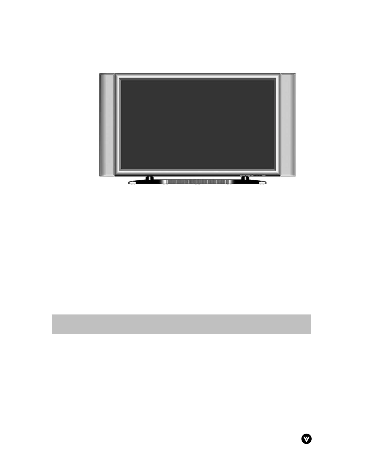
Congratulations on your VIZIO P42 42” Plasma Television purchase. Thank you for your support
of V, Inc. and its Plasma Television product line. The P42 is a precise electronic product and you
should read the following instructions carefully to maximize the performance of the product. It has
passed the Class-B EMC test and the UL and CSA safety certifications and you can be assured
of the highest quality display with the utmost reliability. After you have finished reading the
instructions, put them away in a safe place for future reference.
Note: In some countries or regions, the shape of the power plug and power outlet may
sometimes differ from that shown in the explanatory drawings. However the method of
connecting and operating the unit is the same.
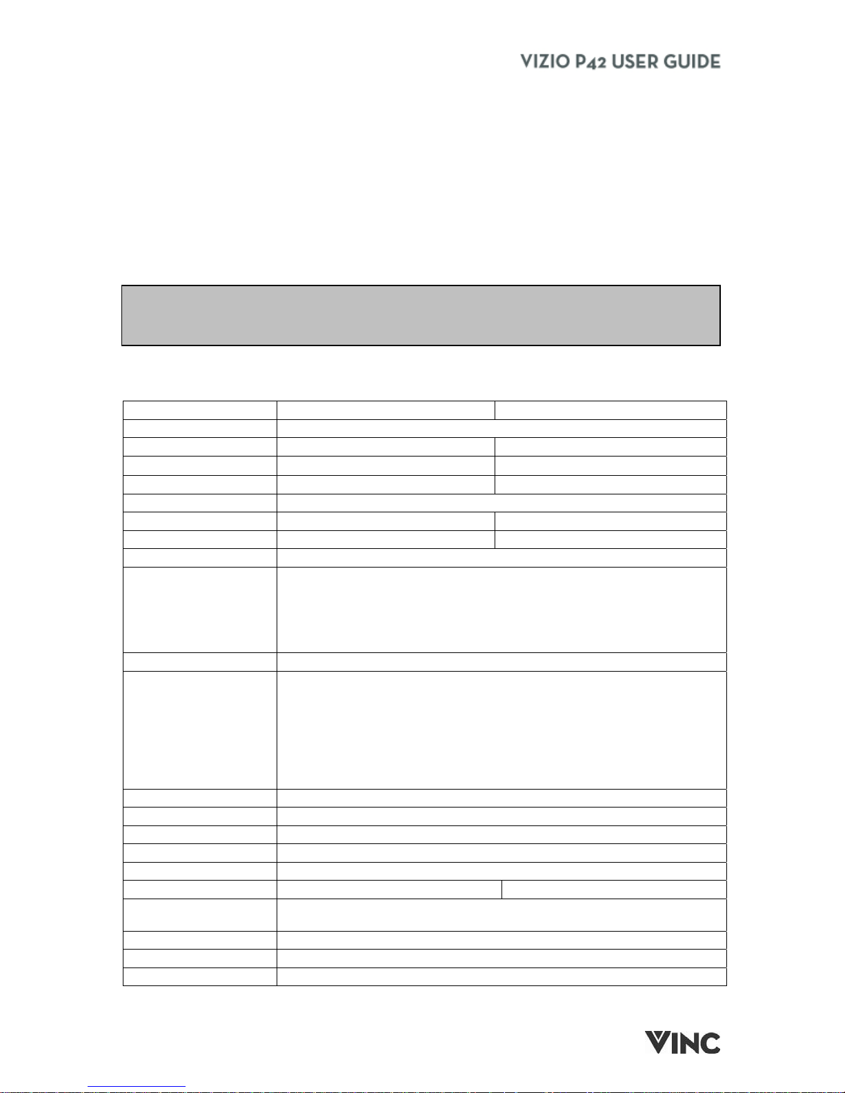
1.2 - Specifications
P42 ED P42 HD
Panel 42", 16:9 Aspect Ratio
Resolution 852 x 480 1024 x 768
Pixel (Dot) Pitch 1.08 mm x 1.08 mm (H x V) 0.90 mm x 0.676 mm (H x V)
Display Compatibility EDTV (480p) HDTV (720p)
Signal Compatibility 480i (SDTV), 480p (EDTV), 720p (HDTV), 1080i (HDTV)
Brightness 1000 cd/m2 1000 cd/m2
Contrast 2000:1 typical 3000:1 typical
Viewing Angle >160 degrees (horizontal and vertical)
2 x Composite Video (2 x RCA), 2 x S-Video (1 x 4-pin DIN), 1 x
Component (3 x RCA, YCbCr Video) & 1 x Component (3 x RCA,
YPbPr Video), 1 x Digital Video (1 x DVI), 1 x Analog RGB (1 x 15-pin
D-Sub), 4 x Audio (2 x RCA, Left + Right), 1 x RF (1 x F Connector for
Inputs
Output 1 x Stereo Audio (1 x RCA, L & R), 1 x subwoofer (1 x RCA)
Component YPbPr, VGA or DVI, HDTV via Component YPbPr, VGA or
Features
Interface 1 x RS232 (9-pin D-sub)
Speakers 2 x 15W
Power
Input IEC Connector for direct power line connection
Voltage Range 100 - 240 Vac at 50/60 Hz.
Power Consumption 360 W average 440 W average
Dimensions
Net Weight 85 lbs w/stand and speakers
Gross Weight 115.8 lbs w/stand and speakers
Certifications UL, C-UL, FCC Class B
internal NTSC Tuner), 1 x Audio (1 x Stereo Mini Jack)
PiP, POP, CC, V-Chip, 3D Comb Filter, 3:2 Pull Down, Gamma
Correction, Scalar and De-interlacer, NTSC Video decoding via RF
(Antenna, Cable or Satellite [Set top box may be required]) or Video
(CVBS, S-Video or Component YCbCr), Progressive Scan Video via
DVI (Set top box may be required), Computer 640x480, 800x600,
1024x768 via VGA or DVI, SRS and BBE Sound enhancement.
40.9" x 25.45" x 5.2" w/o stand or speakers; 48.65" x 27.2" x 10.6"
w/stand and speakers
Version - 7/21/2004
2
Page 4

1.3 - Opening the Package
• The VIZIO P42 is packaged in a carton together with other standard accessories. Any
optional accessories are packed separately in another carton.
• The weight of the Plasma Display is approximately 85 lbs. Due to the size and weight of the
product, it is recommended that it be handled by a minimum of 2 persons.
• The protective glass and the glass substrate are installed on the front of the product. Since
both glasses can be easily scratched or broken, please handle the product gently. Never
place the unit on a surface with the glass facing downwards unless it is on protective
padding.
• When opening the carton, check that the product is in good condition and that all standard
accessories and items are included.
• Save the original box and all packing materials for future shipping needs.
1.4 - Installation
• Please read the user manual carefully before performing the installation.
• The power consumption of the display is approximately 360 Watts for EDTV or 440 W for
HDTV, significantly higher than a typical television. Please use the power cord designated for
the product. When an extension cord is required, use one with the correct power rating. The
cord must be grounded and the grounding feature must not be defeated.
• The product should be installed on a flat surface to avoid tipping. Space should be
maintained between the back of the product and the wall for proper ventilation. See Section
3.2 - Preparing the Plasma for Wall Mounting, p. 25, for additional information.
• Avoid installing the product in the kitchen, bathroom or other places with high humidity dust or
smoke, so as not to shorten the service life of the electronic components.
• Please ensure the product is installed with the screen in landscape orientation. Any 90°
clockwise or counterclockwise installation may induce poor ventilation and subsequent
component damage.
• To protect the screen and avoid screen burn, do not keep a static picture displayed for a
prolonged period of time. This can result in "image sticking" (see below for additional details)
of the image and is not covered by the warranty.
1.4.1 - Image Sticking
The Plasma monitor illuminates phosphors to display images which have a finite illumination
life. After extended periods of illumination, the brightness of the phosphor will be degraded to
such an extent that stationary images would burn-in that part of the screen. Displaying the
same stationary patterns such as black bars, stock tickers, video games or shopping channel
logos and pricing displays, over extended periods of time can leave this type of permanent
image sticking. You can avoid this by mixing your viewing patterns. Do not show the same
stationary image for more than 15% of the total TV viewing in any one week.
NOTE: "Image Sticking" constitutes misuse and is NOT COVERED by the manufacturer's
warranty.
For additional information, please refer to Section 3.4.2.7, page 31 for using the panel
protection feature.
Version - 2/21/2005 3
www.vizioce.com
Page 5

1.5 - Important Safety Guidelines
This product is designed and manufactured to operate within defined design limits, and misuse may result in electric shock or fire.
To prevent the product from being damaged, the following rules should be observed for the installation, use and maintenance of the
product. Read the following safety instructions before operating the display. Keep these instructions in a safe place for future
reference.
• To avoid the risk of electric shock or component damage, switch off the power before connecting other components to the P42
Plasma TV.
• Unplug the power cord before cleaning the P42 Plasma TV. A damp cloth is sufficient for cleaning the P42 Plasma TV. Do not
use a liquid or a spray cleaner for cleaning the product. Do not use abrasive cleaners.
• Always use the accessories recommended by the manufacturer to insure compatibility.
• When moving the P42 Plasma TV from an area of low temperature to an area of high temperature, condensation may form on
the housing. Do not turn on the P42 Plasma TV immediately after this to avoid causing fire, electric shock or component
damage.
• Do not place the P42 Plasma TV on an unstable cart, stand, or table. If the P42 Plasma TV falls, it can injure a person and
cause serious damage to the appliance. Use only a cart or stand recommended by the manufacturer or sold with the P42
Plasma TV.
• A distance of at least 3 feet should be maintained between the P42 Plasma TV and any heat source, i.e. radiator, heater,
oven, amplifier etc. Do not install the product close to smoke. Operating the product close to smoke or moisture may cause
fire or electric shock.
• Slots and openings in the back and bottom of the cabinet are provided for ventilation. To ensure reliable operation of the P42
Plasma TV and to protect it from overheating, be sure these openings are not blocked or covered. Do not place the P42
Plasma TV in a bookcase or cabinet unless proper ventilation is provided.
• Never push any object into the slot on the P42 Plasma TV cabinet. Do not place any objects on the top of the product. It could
short circuit parts causing a fire or electric shock. Never spill liquids on the P42 Plasma TV.
• The P42 Plasma TV should be operated only from the type of power source indicated on the label. If you are not sure of the
type of power supplied to your home, consult your dealer or local power company.
• The power cable must be replaced when using different voltage from that specified in the User Manual. For more information,
contact your dealer.
• The P42 Plasma TV is equipped with a three-pronged grounded plug, a plug with a third (grounding) pin. This plug will fit only
into a grounded power outlet as a safety feature. If your outlet does not accommodate the three-wire plug, have an electrician
install the correct outlet, or use an adapter to ground the appliance safely. Do not defeat the safety purpose of the grounded
plug.
• Do not overload power strips and extension cords. Overloading can result in fire or electric shock.
• The wall socket shall be installed near the equipment and shall be easily accessible.
• Only the marked power source can be used for the product. Any power source other than the specified one may cause fire or
electric shock.
• Do not touch the power cord during lightning. To avoid electric shock, avoid handling the power cord during electrical storms.
• Unplug the unit during a lightening storm or when it will not be used for long period of time. This will protect the P42 Plasma
TV from damage due to power surges.
• Do not attempt to repair or service the product yourself. Opening or removing the back cover may expose you to high
voltages, the risk of electric shock, and other hazards. If repair is required, please contact your dealer and refer all servicing to
qualified service personnel.
• Keep the product away from moisture. Do not expose this appliance to rain or moisture. If water penetrates into the product,
unplug the power cord and contact your dealer. Continuous use in this case may result in fire or electric shock.
• Do not use the product if any abnormality occurs. If any smoke or odor becomes apparent, unplug the power cord and contact
your dealer immediately. Do not try to repair the product yourself.
• Avoid using dropped or damaged appliances. If the product is dropped and the housing is damaged, the internal components
may function abnormally. Unplug the power cord immediately and contact your dealer for repair. Continued use of the
product may cause fire or electric shock.
• Do not install the product in an area with heavy dust or high humidity. Operating the product in environments with heavy dust
or high humidity may cause fire or electric shock.
• Follow instructions for moving the product. Ensure that the power connector and any other cables are unplugged before
moving the product.
• Hold the power connector when removing the power cable. Pulling the power cable itself may damage the wires inside the
cable and cause fire or electric shock. When the product will not be used for an extended period of time, unplug the power
connector.
• To avoid risk of electric shock, do not touch the connector with wet hands.
• Insert batteries in accordance with instructions. Incorrect polarities may cause damage and leakage of the batteries, operator
injury and contamination the remote controller.
• If any of the following occurs please contact the dealer:
• Operating environment: Temperature: 32°F~104°F (0°C ~ 40°C), Humidity: 20% to 85% non-condensing
Version - 2/21/2005 4
o The power connector fails or frays.
o Liquid sprays or any object drops into the P42 Plasma TV.
o The Display is exposed to rain or other moisture.
o The Display is dropped or damaged in any way.
o The performance of the Display changes substantially.
www.vizioce.com
Page 6

1.6 - Television Antenna Connection Protection
External Television Antenna Grounding
If an outside antenna or cable system is to be connected to the Plasma TV, make sure that the
antenna or cable system is electrically grounded to provide some protection against voltage
surges and static charges.
Article 810 of the National Electrical Code, ANSI/NFPSA 70, provides information with regard to
proper grounding of the mast and supporting structure, grounding of the lead-in wire to an
antenna discharge unit, size of the grounding conductors, location of antenna discharge unit,
connection to grounding electrodes, and requirements of the grounding electrode.
Lightning Protection
For added protection of the Plasma TV during a lightning storm or when it is left unattended or
unused for long periods of time, unplug the Plasma TV from the wall outlet and disconnect the
antenna or cable system.
Power Lines
Do not locate the antenna near overhead light or power circuits, or where it could fall into such
power lines or circuits.
Version - 2/21/2005 5
www.vizioce.com
Page 7
1.7 - Package Contents
VIZIO P42 Plasma TV
VIZIO Universal Remote Control
42 mm Stand-Off Screws for the Bottom of the TV – 2 QTY
55 mm Stand-Off Screws for the Top of the TV – 2 QTY
Power Cord
RCA Cable
This User Guide
IMPORTANT: Save the original box and all the packing material for future shipping needs.
Note: Your product may also include various other accessories depending on region of
purchase.
Version - 2/21/2005 6
www.vizioce.com
Page 8
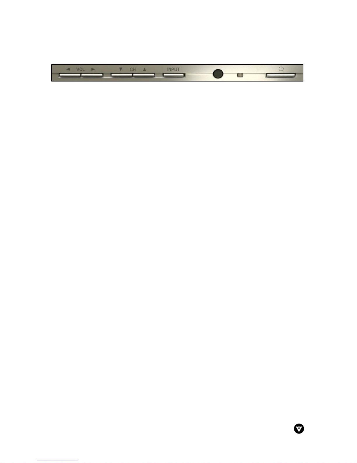
1.8 - Front Panel Controls
Volume ◄/► - These buttons are used to increase or decrease the speaker volume. While the
OSD is active, these buttons function as adjustment controls in the OSD menus.
Channel d/c – These buttons are used to increase or decrease the selected channels. While
the OSD is active, these buttons function as select controls in the OSD menus.
Input - Repeated pressing of this button steps through the input sources in sequence. Once you
have stepped through the entire sequence, you will return to the beginning.
Remote Control Sensor – This is the window that passes all of the remote signals to the sensor.
Point the remote control directly at this window for the best response to the remote signal.
Power LED - Lights green when powered on.
Power - Switch the TV on by pressing the button once. Press the button again to turn the TV off.
Version - 2/21/2005 7
www.vizioce.com
Page 9
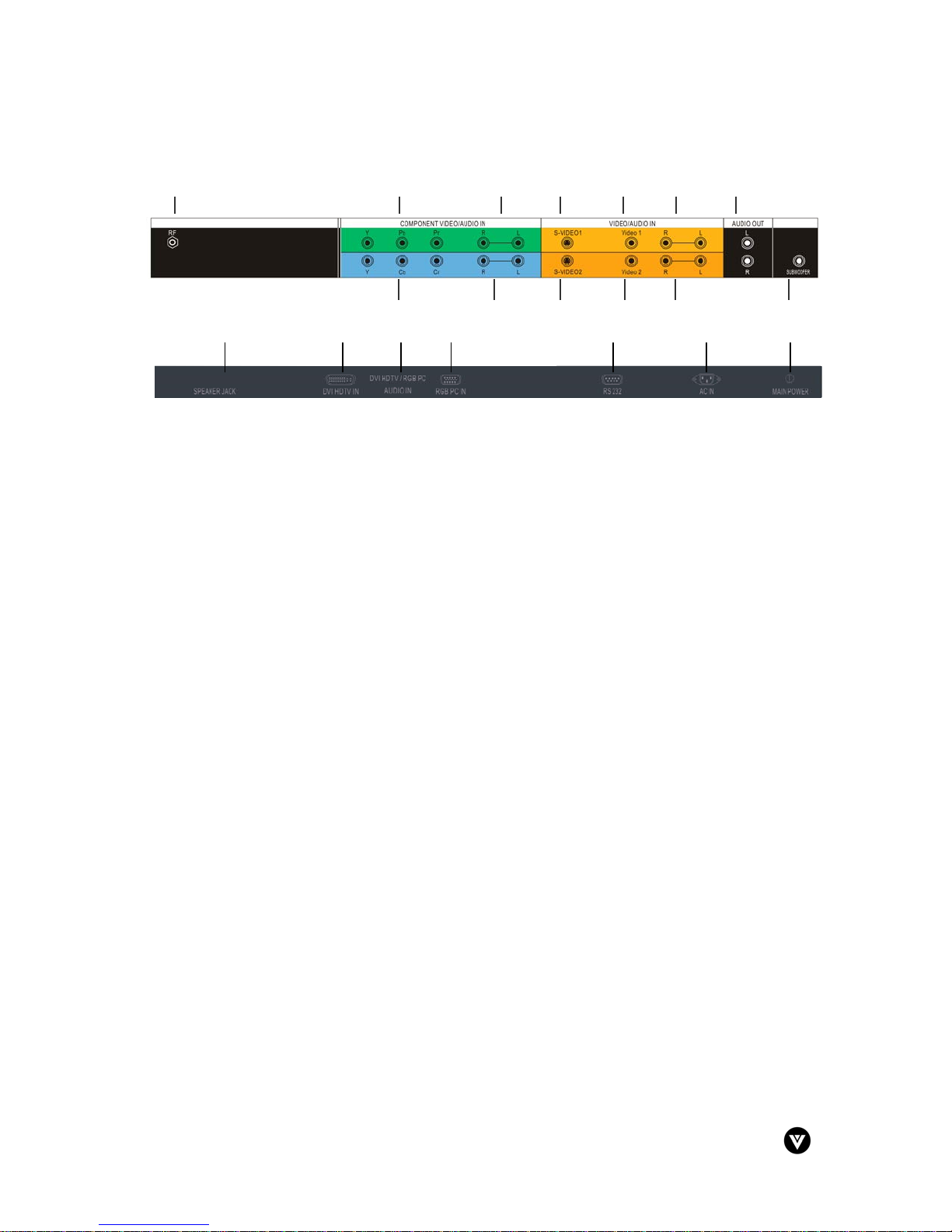
1.9 - Rear Panel Connections
1 2 3 4 5 6 7
14 15 16 17 18 19 20
8 9 10 11 12 13
1. RF (TV Input) – Connect to the antenna, satellite or cable service
2. Component (YPbPr) Input - Connect the external video devices with component output,
such as a DVD player or set-top box.
3. Audio In, Right and Left (R/L) – Connect the external audio from the component video
source such as a DVD player or set-top box.
4. S-Video1 – Connect the S-Video to external video device such as VCR, DVD and video
games.
5. Video1 – Connect the composite video to external video device such as VCR, DVD and
video games.
6. Audio In, Right and Left (R/L) – Connect the external audio from the S-Video or
composite video source such as a VCR or DVD player.
7. Audio Out, Left and Right (L/R) – Connect the audio from the Plasma to an external
amplifier.
8. Component (YCbCr) Input - Connect the external video devices with component output,
such as a DVD player or set-top box.
9. Audio In, Right and Left (R/L) – Connect the external audio from the component video
source such as a DVD player or set-top box.
10. S-Video2 – Connect the S-Video to external video device such as VCR, DVD and video
games.
11. Video2 – Connect the composite video (yellow) to external video device such as VCR,
DVD and video games.
12. Audio In, Right and Left (R/L) – Connect the external audio from the S-Video or
composite video source such as a VCR or DVD player.
13. Subwoofer – Connect an external subwoofer to Plasma.
14. Speaker Jacks – Connect speakers to Plasma.
15. DVI HDTV In – Connect a DVD multimedia player, computer or set-top box through the
20-pin connection. This is a digital only connector.
16. DVI HDTV / RGB PC Audio In – Connect the audio from a computer, DVD multimedia
player or set-top box.
17. RGB PC In – Connect the video from a computer or set-top box.
18. RS232 – To be used for factory service and support.
19. AC In – Connect one end of the power cord here and connect the other end of the power
cord to a wall socket.
20. Main Power Switch – Turn the AC In power on/off.
Version - 2/21/2005 8
www.vizioce.com
Page 10
1.10 - VIZIO Universal Remote Control
8
9
9
0
6
528
3
3
35 36
5
6
3
30 33 3
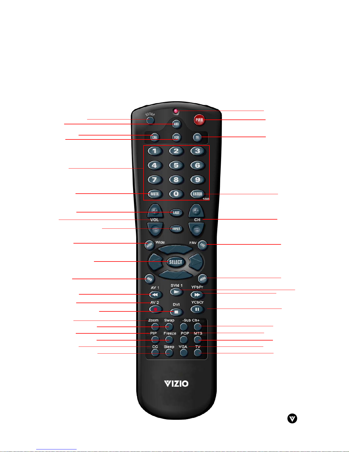
The VIZIO Universal Remote Control is a comprehensive remote that can be used to control up to
four different components. The remote control button functions are explained on the following
pages.
VIZIO Universal Remote Control Button Description
1
4
2
7
11
18
15
26
12
23
29
20
13
17
24
27
4
1
14
1
1
22
1
2
21
2
Version - 2/21/2005 9
www.vizioce.com
Page 11
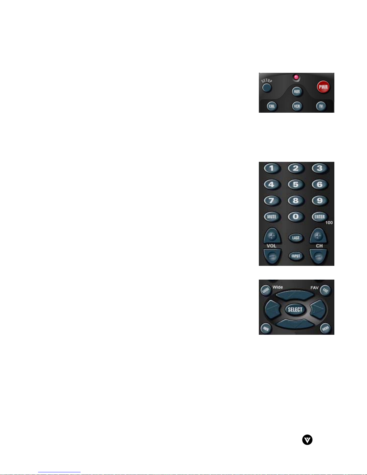
1.10.1 - Key Remote Control Functions
1. SETUP - This button starts all programming sequences.
2. Remote LED – Blinks when the remote is being programmed or is
sending a signal to your Plasma Display.
3. POWER - Press this key to turn the Plasma Display On from
Standby mode. Press it again to return to the Standby mode.
4. AUX – This button selects a programmed component.
5. CBL – This button selects a programmed cable TV set-top box or selects a programmed
satellite TV set-top box.
6. VCR – This button selects a programmed VCR.
7. TV – This button selects a programmed TV. Pre-programmed for the VIZIO P42 Plasma
TV.
8. Number Button Pad – These buttons select a channel or
password.
9. MUTE – This button turns the sound on and off.
10. 100/Enter – This button enters a channel number greater than 100
in TV mode. Additionally, it works as an ENTER button in other
video modes.
11. VOL (+ or -) – These buttons turn volume up or down.
12. LAST – This button recalls the previously viewed channel.
13. INPUT – This button changes the input source.
14. CH (+ or -) – These buttons change the channels up or down.
15. WIDE/GUIDE – This button cycles through standard and
widescreen viewing modes or accesses programming guides, such
as the one that comes with a satellite dish. GUIDE does not work
in TV mode.
16. FAV/EXIT – This button exits the component, guide or OSD
menus. Additionally, it retrieves your favorite channels in TV
mode.
dcfe - These buttons navigate the on-screen display (OSD)
menus.
17. SELECT – This button works to select your chosen options in on-screen display (OSD)
menus.
18. INFO – This button turns the image and system information display On or Off.
19. MENU – This button is used to select the OSD menu pages in the following sequence:
PictureDAudioDSourceDGraphicDTVDClockDSetup
Version - 2/21/2005 10
www.vizioce.com
Page 12
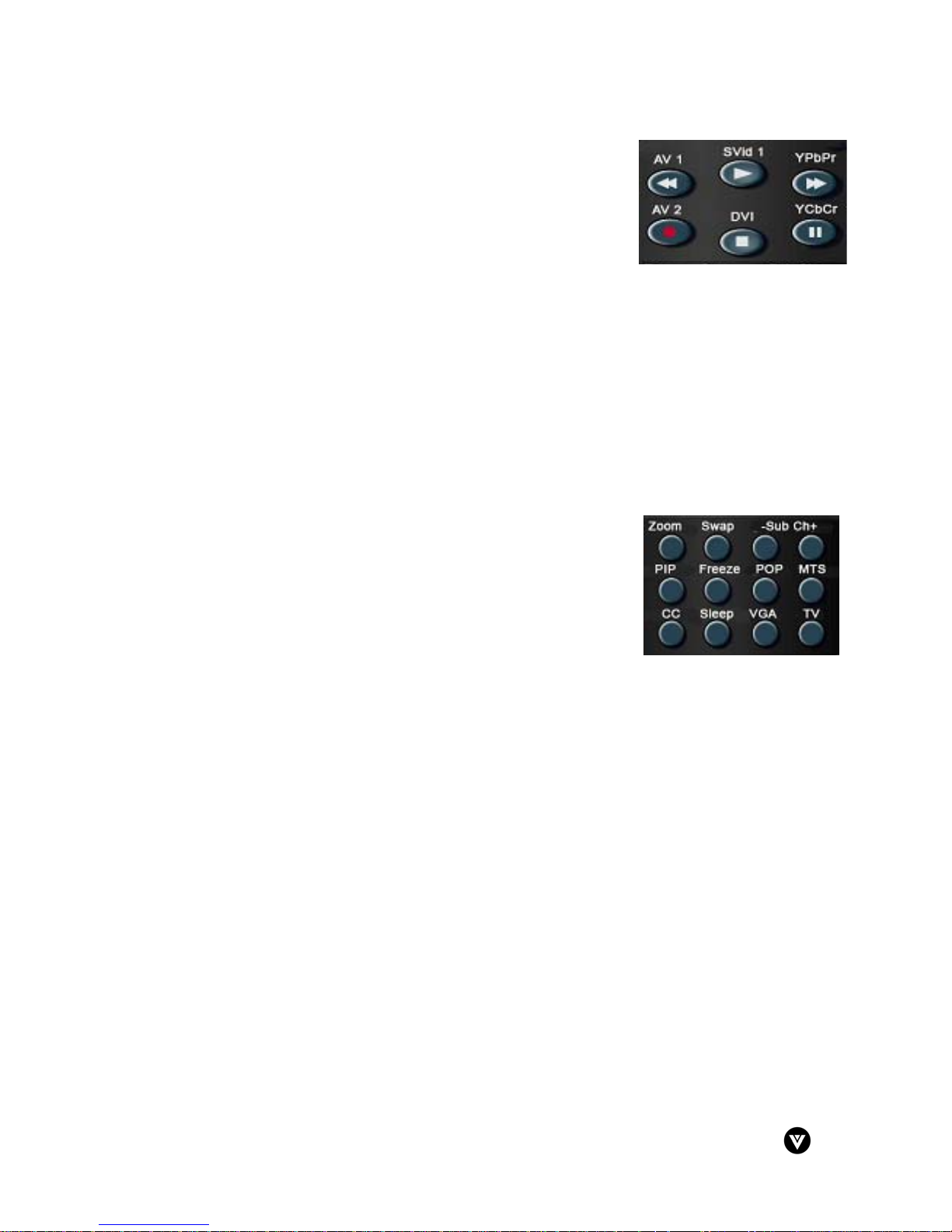
20. Reverse/AV1 – This button rewinds the CD, DVD or VCR
when the component is activated with the remote control.
Additionally, this button will select the AV1 component in TV
mode.
21. Play/SVid1 – This button plays the CD, DVD or VCR when the
component is activated with the remote control. Additionally,
this button will select the SVid1 component in TV mode.
22. Forward/YPbPr – This button forwards the CD, DVD or VCR when the component is
activated with the remote control. Additionally, this button will select the YPbPr
component in TV mode.
23. Record/AV2 – This button functions as a VCR Record when the component is activated
with the remote control. Additionally, this button will select the AV2 component in TV
mode.
24. Stop/DVI – This button stops the CD, DVD or VCR when the component is activated with
the remote control. Additionally, this button will select the DVI component in TV mode.
25. Pause/YCbCr – This button pauses the CD, DVD or VCR when the component is
activated with the remote control. Additionally, this button will select the YCbCr
component in TV mode.
26. ZOOM - Use this key to zoom the image in or out.
27. Swap – Used to swap the inputs from the main and PiP or
POP picture mode.
28. –SubCh+ - These buttons are used to select the channels
within the PIP.
29. PIP – Use this key to activate the picture-in-picture mode.
30. FREEZE – Press this key to "Freeze-Frame", the current
screen. You may press this key again to continue playing or
play will resume automatically after one minute.
31. POP – Use this key to activate the picture-on-picture mode.
32. MTS – Press this key to select Stereo, SAP (separate audio program) or Mono audio.
This function is available in the TV mode.
33. CC – Press this key to select closed caption options.
34. Sleep – Press this key to select the sleep options. User can adjust the sleep timer in 5
minute increments.
35. VGA – This button selects a programmed VGA display.
36. TV - This button selects a programmed TV. Pre-programmed for the VIZIO P42 Plasma
TV.
Note: The remote control layout is for reference only.
Version - 2/21/2005 11
www.vizioce.com
Page 13
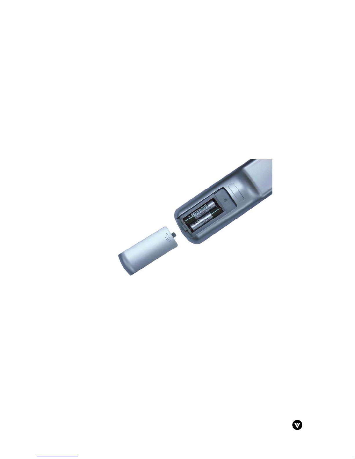
1.10.2 - Insertion of Batteries in the Remote Control
Insert two AA batteries into the remote control. Make sure that you match the (+) and (-) symbols
on the batteries with the (+) and (-) symbols inside the battery compartment. Re-attach the
battery cover.
Precautionary Tips for Inserting the Batteries:
• Only use the specified AA batteries.
• Do not mix new and old batteries. This may result in cracking or leakage that may pose a
fire risk or lead to personal injury.
• Inserting the batteries incorrectly may result in cracking or leakage that may pose a fire
risk or lead to personal injury.
• Dispose of the batteries in accordance with local laws and regulations.
• Keep the batteries away from children and pets.
Version - 2/21/2005 12
www.vizioce.com
Page 14
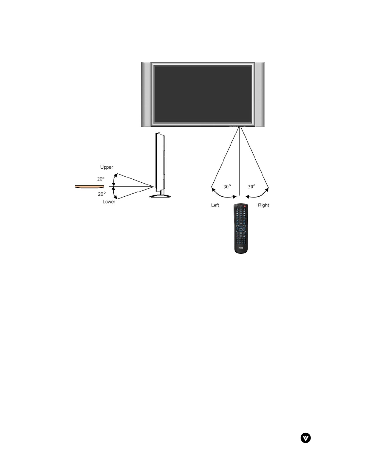
1.10.3 - Remote Control Range
• Point the remote control at the remote control sensor to transmit the commands.
• Do not place any obstacles between the remote control and the receiver window.
• The effective range of the remote control is approximately 32 feet (10 meters) from the
front of the receiver window, 30º to the left and right, 20º up and down.
1.10.4 - Precautions for the VIZIO Universal Remote Control
• Remote control should be kept dry and away from heat sources. Avoid humidity.
• If the display responds erratically to the remote control or does not respond at all, check
the batteries. If the batteries are low or exhausted, replace them with fresh batteries.
• When not using the remote control for a long period of time, remove the batteries.
• Do not take apart the batteries, heat them, or throw them into a fire.
• Do not subject the remote control to undue physical stress, such as striking or dropping it.
• Do not attempt to clean the remote control with a volatile solvent. Wipe it with a clean,
damp cloth.
Version - 2/21/2005 13
www.vizioce.com
Page 15

Chapter 2 - Connecting Components
2.1 - Which Video Connection Should I Use?
The VIZIO P42 Plasma TV has five different ways to connect your video equipment from a basic
one to the most advanced for digital displays.
Connection
Cable and Connector Description
Quality
OK
Basic
Good
Better
Best
Coaxial RF. This is the only connection that has the audio
and the video in one cable. If you have an antenna, this is
the only way you can connect it to the Plasma TV. If you
have a VCR, you can connect your antenna/cable to the
VCR RF Input and connect the VCR RF Output to this
connector.
Composite. The complete video signal is carried through
this single pin connector. This is the most commonly used
video connection.
S-Video. The video signal is separated into two signals,
one containing the black-and-white information and the
other containing the color information. Separating the
color in this way avoids ‘cross color’ effects where closely
spaced black and white lines are erroneously displayed in
color. It also enables text to be displayed more sharply.
Component. The video signal is separated into three
signals, one containing the black-and-white information
and the other two containing the color information. This
enhancement over S-Video takes advantage of the
superior picture provided by progressive scan DVD
players and HDTV formats.
Digital Video (DVI). All of the picture information is
received digitally coded and it does not convert the signal
from digital to analog. The other inputs are converted
from analog to digital by the Plasma TV. Movies are
digitally encoded on DVD’s and so by using a component
such as the BRAVO D2 DVI Enabled DVD Player from V,
Inc. with a DVI output it will produce the ultimate picture
performance.
Version - 2/21/2005 14
www.vizioce.com
Page 16

2.2 - Connecting Your DVD Player
You have several options for connecting your DVD player to your new P42 Plasma TV - DVI,
Component, S-Video, and Composite inputs. Based on your home theater configuration, you can
decide which option is the right one for you.
2.2.1 - Using Digital Video
DVD players that have a digital interface compliant with the DVI (Digital Visual Interface)
standard, such as the BRAVO D2 DVI Enabled DVD Player from V, Inc., should be connected to
the DVI input of the VIZIO P42 Plasma TV.
Note:
a) Use TMDS signals conforming to DVI standards. The TMDS input is a single link input.
b) To maintain the display qu ality, use a DVI cable from V, Inc. that is 10 meters or less.
Installation:
1. Turn off the power to the Plasma TV and DVD player.
2. Connect a DVI-D cable to the DVI output of your DVD player and the other end to the DVI
input in the rear of your Plasma TV.
3. Connect the Audio on your DVD player to the DVI HDTV/RGB PC Audio In next to the
DVI In connection in the rear of your Plasma TV.
4. Turn on the power to the Plasma TV and your DVD player.
5. Select DVI using the INPUT button on the front of the Plasma TV.
Note:
a) The DVI input on your Plasm a TV supports Hig h-bandwidth Content Protection
(HDCP). HDCP encrypts the transmission between the video source and the di gital
display for added security and protection.
b) Refer to your DVD pla ye r u ser manual for more information about the video output
requirements of the product.
Version - 2/21/2005 15
www.vizioce.com
Page 17

2.2.2 - Using Component Video
Installation:
1. Turn off the power to the Plasma TV and DVD player.
2. Connect the Y (green color) connector on the rear of your DVD player to the
corresponding Y (green color) connector in the Component Video/Audio In connections
(green band) in the rear of your Plasma TV.
3. Connect the Pb (blue color) connector on the rear of your DVD player to the
corresponding Pb (blue color) connector in the Component Video/Audio In connections
(green band) in the rear of your Plasma TV.
4. Connect the Pr (red color) connector on the rear of your DVD player to the corresponding
Pr (red color) connector in the Component Video/Audio In connections (green band) in
the rear of your Plasma TV.
5. Connect the R (red color) and L (white color) audio connectors on the rear of your DVD
player to the R (red color) and L (white color) audio input connectors (green band) on the
rear of your Plasma TV.
6. Turn on the power to the Plasma TV and DVD player.
7. Select YPbPr using the INPUT button on the front of the Plasma TV.
Note:
a) Refer to your DVD pla ye r u ser manual for more information about the video output
requirements of the product.
b) If you are already using the YPbPr input for another component, or you do not want to
use the YPbPr input for the DVD player, you can connect the DVD player to the
YCbCr in the Component Video/Audio IN group of connections (blue band).
Version - 2/21/2005 16
www.vizioce.com
Page 18

2.2.3 - Using S-Video
Installation:
1. Turn off the power to the Plasma TV and DVD player.
2. Connect the S-Video jack on the rear of your DVD player to the S-Video1 jack in the
Video/Audio IN connections (yellow band) in the rear of your Plasma TV.
3. Connect the R (red color) and L (white color) audio connectors on the rear of your DVD
player to the R (red color) and L (white color) audio input connectors in the Video/Audio
IN connections (yellow band) in the rear of your Plasma TV.
4. Turn on the power to the Plasma TV and DVD player.
5. Select S-Video1 using the INPUT button on the front of the Plasma TV.
Note:
a) If you are already using the S-Video1 input for another component, or you do not want
to use the S-Video1 input for the DVD player, you can connect the DVD player to the
S-Video2 in the Video/Audio IN group of connections (orange band).
b) Refer to your DVD pla ye r u ser manual for more information about the video output
requirements of the product.
Version - 2/21/2005 17
www.vizioce.com
Page 19

2.2.4 - Using Composite Video
Installation:
1. Turn off the power to the Plasma TV and DVD player.
2. Connect the Video
(yellow color) connector on the rear of your DVD player to the Video1
connector in the Video/Audio IN connections (yellow band) in the rear of your Plasma TV.
3. Connect the R (red color) and L (white color) audio connectors on the rear of your DVD
player to the R (red color) and L (white color) audio input connectors in the Video/Audio
IN connections (yellow band) in the rear of your Plasma TV.
4. Turn on the power to the Plasma TV and DVD player.
5. Select Video1 using the INPUT button on the front of the Plasma TV.
Note:
a) If you are already using the Video1 input for another component, or you do not want to
use the Video1 input for the DVD player, you can connect the DVD player to the
Video2 in the Video/Audio IN group of connections (orange band).
b) Refer to your DVD pla ye r u ser manual for more information about the video output
requirements of the product.
Version - 2/21/2005 18
www.vizioce.com
Page 20

2.3 - Connecting Your HDTV Set-Top Box
You have several options for connecting your HDTV Set-Top Box to your new P42 Plasma TV:
Component, DVI and RGB inputs. Based on your home theater configuration, you can decide
which option is the right one for you.
2.3.1 - Using Digital Video
HDTV Set-Top Boxes that have a digital interface compliant with the DVI (Digital Visual Interface)
standard can be connected to the DVI input of the Plasma TV.
Note:
a) Use TMDS signals conforming to DVI standards. The TMDS input is a single link
input.
b) To maintain the display qu ality, use a DVI cable from V, Inc. that is 10 meters or less.
Installation:
1. Turn off the power to the Plasma TV and HDTV Set-Top Box.
2. Connect a DVI-D cable to the DVI output of your HDTV Set-Top Box and the other end to
the DVI input in the rear of your Plasma TV.
3. Connect the Audio Out on your HDTV Set-Top Box to the DVI HDTV/RGB PC Audio In of
your Plasma TV.
4. Turn on the power to the Plasma TV and your HDTV Set-Top Box.
5. Select DVI using the INPUT button on the front of the Plasma TV.
Note:
a) The DVI input on your Plasm a TV supports Hig h-bandwidth Content Protection
(HDCP). HDCP encrypts the transmission between the video source and the di gital
display for added security and protection.
b) Refer to your HDTV Set-To p Box user manual for more information about the video
output requirements of the product or consult your satellite or cable operator.
Version - 2/21/2005 19
www.vizioce.com
Page 21

2.3.2 - Using RGB Video
Installation:
1. Turn off the power to the Plasma TV and HDTV Set-Top Box.
2. Connect a 15-pin D-Sub RGB cable to the RGB output of your HDTV Set-Top Box and
the other end to the RGB IN input in the rear of your Plasma TV.
3. Connect the Audio Out on your HDTV Set-Top Box to the DVI HDTV/RGB PC Audio In
on your Plasma TV.
4. Turn on the power to the Plasma TV and your HDTV Set-Top Box.
5. Select RGB using the INPUT button on the front of the Plasma TV.
Note: Refer to your HDTV Set-Top Box user manual for more information about the video
output requirements of the product or consult your satellite or cable operator.
2.4 - Connecting Your VCR or Video Camera
Installation:
1. Turn off the power to the Plasma TV and VCR or video camera.
2. Connect the S-Video jack on your VCR or video camera to the S-Video jack in the
Video/Audio IN connections (yellow band) in the rear of your Plasma TV.
3. Connect the R (red color) and L (white color) audio connectors on your VCR or video
camera to the R (red color) and L (white color) audio input connectors in the Video/Audio
IN connections (yellow band) in the rear of your Plasma TV.
4. Turn on the power to the Plasma TV and VCR or video camera.
5. Select S-Video1 using the INPUT button on the front of the Plasma TV.
Note:
a) If you are already using the S-Video1 input for another component, or you do not want
to use the S-Video1 input for the VCR or video camera, you can connect the VCR or
video camera to the S-Video2 in the Video/Audio IN group of connections (orange
band).
b) Refer to your VCR o r vid eo camera user manual for more information about the video
Version - 2/21/2005 20
output requirements of the product.
www.vizioce.com
Page 22

2.5 - Connecting Coaxial (RF)
There are several options for connecting your antenna or cable to your new P42 Plasma TV directly to the TV or through your VCR. Based on your home theater configuration, you can
decide which option is the right one for you.
2.5.1 - Using Your Antenna or Cable TV
Installation:
1. Turn off the power to the Plasma TV.
2. Connect the coaxial (RF) connector from your antenna or cable box to the RF connector
on the rear of your Plasma TV.
3. Turn on the power to the Plasma TV
4. Select TV1 using the INPUT button on the front of the Plasma TV.
See page 30 for selecting the TV source within the OSD menus (antenna, cable, HRC
and IRC).
Note: Make sure the antenna or cable TV is correctly grounded.
2.5.2 - Using the Antenna through Your VCR
Installation:
1. Turn off the power to the Plasma TV and VCR.
2. Connect the “Output to TV” (RF Out or Antenna Out) connector on the rear of your VCR
to the RF connector on the rear of your Plasma TV.
3. Turn on the power to the Plasma TV and VCR.
4. Select TV1 using the INPUT button on the front of the Plasma TV.
5. Select Channel 3 or 4 to match the channel selected on the rear of your VCR.
Note:
a) If you have an off-air antenna or cable TV, connect the off-air antenna or TV cable to
the RF connector on the rear of your VCR.
b) Make sure the antenna or cable TV is correctly grounded.
Version - 2/21/2005 21
www.vizioce.com
Page 23

2.6 - Connecting External Amplified Speakers
Installation:
1. Turn off the power to the Plasma TV and external speakers.
2. Connect the R (red color) and L (white color) audio connectors on the rear of your
speakers to the R (red color) and L (white color) audio output connectors in the AUDIO
OUT connections in the rear of your Plasma TV.
3. Connect the subwoofer connector on the rear of your speaker to the SUBWOOFER
connection in the rear of your Plasma TV.
4. Turn on the power to the Plasma TV and speakers.
5. Press the MENU button on the remote control to activate the on-screen display (OSD).
6. Press the f on the remote control until AUDIO is highlighted and press the SELECT
button to select this Sub Menu.
7. Press the d on the remote control until Subwoofer is highlighted and press the f on the
remote control to change from Subwoofer from Off to On.
Version - 2/21/2005 22
www.vizioce.com
Page 24

2.7 - Connecting an External Receiver or Amplifier
You can connect an external receiver or amplifier to your Plasma TV. Your Plasma TV is
equipped with an external speaker switch that can automatically send a remote turn-on/off signal
to the connected external receiver or amplifier.
Installation:
1. Turn off the power to the Plasma TV and receiver or amplifier.
2. Connect the R (red color) and L (white color) audio connectors on the rear of your
receiver or amplifier to the R (red color) and L (white color) audio output connectors in the
AUDIO OUT group on the rear of your Plasma TV.
3. Turn on the power to the Plasma TV and receiver or amplifier.
4. Press the SELECT button on the remote control to activate the on-screen display (OSD).
5. Press the f on the remote control or the Volume fbutton on the front of your Plasma TV
once to highlight AUDIO and press the ENTER button to select this Sub Menu.
6. Press the d on the remote control until LINE OUT is highlighted and press the f on the
remote control to change from Fix to Variable so that you can use the Volume buttons on
the front of your Plasma TV.
Version - 2/21/2005 23
www.vizioce.com
Page 25

2.8 - Connecting a Computer
Installation:
1. Turn off the power to the Plasma TV and Computer.
2. Connect a 15-pin D-sub RGB cable to the RGB output of your computer and the other
end to the RGB input in the rear of your Plasma TV.
3. Connect the Audio Out on your computer to the DVI HDTV/RBG PC Audio In at the rear
of your Plasma TV.
4. Turn on the power to the Plasma TV and your computer.
5. Select RGB using the INPUT button on the front of the Plasma TV.
Note: Refer to your computer user manual for more information about the video output
requirements of the product.
Version - 2/21/2005 24
www.vizioce.com
Page 26

Chapter 3 - Getting Started
3.1 - Turning your Plasma TV On and Off
1. Plug the power cord into an AC wall socket.
2. Press the AC switch button on the back of the
Plasma TV. The POWER indicator on the front
panel will light orange.
3. Press the POWER button on the front panel or the
POWER button on the remote control to power on
the Plasma TV. The POWER indicator on the front
panel will light green.
4. Select input source for the Plasma TV, via either
OSD menu or remote control.
5. If connecting to antenna, cable or other RF
source on TV inputs, see page 30 to configure the
product to receive all available channels.
3.2 - Preparing the Plasma for Wall Mounting
The VIZIO P42 can either be kept on the base stand or mounted to the wall for viewing. If you
choose to mount the P42 to the wall, you will need to attach 4 stand-off screws (included within
the product packaging) to back panel so that the TV will fit evenly against a wall mount. Please
follow the instructions below for removing the base stand and adding the stand-off screws to
prepare the TV to be mounted.
To remove the stand base:
1. Unplug all the cables and cords from the Plasma
TV.
2. Place the Plasma TV face down on a soft and flat
surface (blanket, foam, cloth, etc) to prevent any
damage to the display.
3. Remove the 6 screws on the stand base of the
Plasma TV and the 2 screws on the upper part of
the display.
4. The stand can now be removed from the back
panel.
To add the stand-off screws to the back panel:
1. Secure both 55 mm stand-off screws in the screw
holes on the top side of the back panel.
2. Secure both 42 mm stand-off screws in the screw
holes on the bottom side of the back panel.
The Plasma TV will now fit flush against a Plasma TV
wall mount. Please make sure to read the directions of
your specific wall mount to properly hang the P42.
Version - 2/21/2005 25
www.vizioce.com
Page 27

3.3 - Adjusting Basic Plasma TV Settings
Volume
To increase the volume, press and hold the VOL + button on the front panel or remote
control until the desired level is reached.
To decrease the volume, press and hold the - VOL button on the front panel or remote
control until the desired level is reached.
TV Channels
To step up through the available TV channels, press the CH + button on the front panel
or remote control once for the next channel or hold it depressed until the desired channel
is reached.
To step down through the available TV channels, press the - CH button on the front panel
or remote control once for the previous channel or hold it depressed until the desired
channel is reached.
Mute
Press the MUTE button on the remote control to turn off the sound; press the button
again to cancel the MUTE feature and turn the sound on.
Wide
Using this feature you can watch video content in Aspect, Wide or 1:1 mode. Press the
WIDE button on the remote control to switch among the modes.
Version - 2/21/2005 26
www.vizioce.com
Page 28

3.4 - Using the On-Screen Display (OSD)
The remote control or the bottom control keys on the front panel of the Plasma TV can control all
the function settings. The on-screen display (OSD) allows you to adjust and save contrast,
brightness and other settings. The Plasma TV will save changes made to the settings even if the
Plasma TV is turned off.
3.4.1 - Menu Operations
The OSD consists of a Main Menu of items and each of these items has a Sub Menu associated
with it that the OSD will switch to when the item is selected.
1. Press the MENU button on the remote control and
the Main Menu will be displayed on the screen, as
shown opposite.
2. Use the e/f buttons on the remote control to
highlight the feature you wish to select.
3. Press the SELECT button on the remote control to
select the feature. The Main Menu will now change
to the Sub Menu of the feature selected, as shown
opposite.
4. Use the c /d buttons on the remote control to
highlight the option you wish to adjust.
5. Adjust the level or change the setting of the
selected option by pressing e/f buttons on the
remote control.
Once an option is selected, the Sub Menu of the
OSD will change to a status bar at the bottom of the
page.
6. Press the SELECT button to return back to the main screen once you have finished
making the necessary adjustment.
7. Repeat steps 4 and 5 to adjust additional options.
8. Once the adjustment is completed, press the EXIT on the remote control repeatedly to
return to the Main Menu or to exit the OSD.
Version - 2/21/2005 27
www.vizioce.com
Page 29

3.4.2 - OSD Menus and Options
The OSD menus and options are used to adjust various settings on your Plasma TV.
3.4.2.1 - PICTURE
Brightness – Adjusts the brightness of the picture. Users
may need to readjust the brightness after the
Plasma TV warms up.
Contrast – Adjusts the contrast of the picture.
Color – Adjusts the color saturation making colors more
intense. Note: this option is not selectable when TV
is in PC mode.
Tint – Adjusts the color of flesh tones. Note: this option
is not selectable when TV is in PC mode.
Sharpness – Adjust the amount of detail enhancement.
Note: this option is not selectable when TV is in PC
mode.
Color Temp. – Adjusts the color temperature. Users can
choose from either normal or user.
3.4.2.2 - AUDIO
Volume – Adjusts the volume.
Bass – Adjusts the bass.
Treble – Adjust the treble.
Balance – Adjusts the balance level between the
channels.
Speaker – Turn speakers off or on.
Line Out – Sets line out level to either variable or fix
Variable – Sound level will change with the setting
on the TV.
Fix – Sound output level is constant and volume is
controlled by an externally connected
amplifier.
Subwoofer – Turn subwoofer on or off.
MTS – Multi-sound selection. Select from Mono,
Stereo or SAP (separate audio program).
Version - 2/21/2005 28
www.vizioce.com
Page 30

3.4.2.3 - SOURCE
Main Screen – Selects main screen sources.
TV1, TV2, AV1, AV2, SV1, SV2, YPbPr, YCbCr,
RGB, DVI
Sub Screen – Selects Sub Screen sources.
Off, TV, AV1, AV2, SV1, SV2, YPbPr, YCbCr,
RGB, DVI
Audio From – Select Main or Sub Screen audio
sources.
Display Mode – Select Full, PIP or POP.
Wide Mode – Changes the Sub Screen size. Choose
between aspect, wide 1:1. Note: This is not
available when POP is selected.
The following options will appear when PiP is selected:
PIP ASPECT – Select Aspect or Wide
PIP H.POS – Sub-Screen display H. Position
adjustment.
PIP V.POS – Sub-Screen display V. Position adjustment.
PIP SIZE – Sub-Screen display size adjustment.
3.4.2.4 - GRAPHIC
This menu is only available in the PC mode.
Auto Adjust – Auto adjusts the horizontal phase of the
image.
H. Position – Horizontal position on the image
adjustment.
V. Position – Vertical position on the image adjustment.
Phase – Phase adjustment.
Clock – Clock adjustment.
Resolution – Display source resolution frequency.
Version - 2/21/2005 29
www.vizioce.com
Page 31

3.4.2.5 - TV
Input – Select TV source type from one of the
following: ANT, Cable, HRC and IRC.
Caption Mode – Turn the close caption OFF or CC1,
CC2, CC3, CC4, TT1, TT2, TT3, TT4.
Auto Scan – Auto scan on TV channels.
Add/Del Channels – Manually add and delete selected
channels.
Parental Controls – Adjust parental control settings.
Password Edit – Change user password.
TV Rating – Choose either B (Block) or U (Unblock).
Options include the following:
• TV-Y (all children)
• TV-Y7 (older children)
• TV-G (general audience)
• TV-PG (guidance suggested)
• TV-14 (strongly cautioned)
• TV-MA (mature audience)
You can also customize these ratings for:
• FV (fantasy violence)
• V (violence)
• L (adult language)
• S (sexual situations)
• D (sexual dialog)
For additional information, see “Using the Parental Controls”, page 32.
MPAA Rating - Choose either B (Block) or U (Unblock). Options include the following:
• G (General audience)
• PG (Parental guidance suggested)
• PG-13 (Recommended for children 13
years of age and older)
• R (mature audience)
• NC-17 (no one under 17 years of age)
• X (Adult audience only)
For additional information, see “Using the Parental Controls”, page 32.
Version - 2/21/2005 30
www.vizioce.com
Page 32

3.4.2.6 - CLOCK
Date – Display present date in MM/DD/YY format.
Time – Display present time.
Timer1 – Set the time and duration to automatically
turn on.
Timer2 – Set the time and duration to automatically
turn on.
Sleep Timer – Sets sleep timer either on or off. Users
can select the number of minutes the Plasma TV
waits before it automatically turns off in 5-minute
increments. Maximum available time is 120
minutes.
3.4.2.7 - SETUP
OSD H Posi. – Adjusts the horizontal position of the
OSD within the display image.
OSD V Posi. – Adjusts the vertical position of the OSD
within the display image.
OSD Timeout – Specifies the number of seconds the
OSD menu is displayed before it automatically
turns off.
Language – Changes the language of the OSD menu.
Panel Protection – Use to prevent image sticking.
Orbit Range – Select image moving range.
Orbit Cycle – Select image moving period range.
INFO – Display Input Source, Type and Signal.
Reset – Reset default value.
Ver. – Software version.
Version - 2/21/2005 31
www.vizioce.com
Page 33

3.4.3 - Using the Parental Controls
The Parental Controls feature prevents viewers from watching programs that are not ageappropriate, such as programs containing violence or adult language.
1. Press the TV component button.
2. Press the MENU button on the remote control and the Main Menu will be
displayed on the screen.
3. Press f until the TV menu is highlighted. Then press SELECT.
4. Press d until Parental Controls is highlighted. Press SELECT.
5. Enter your password. If you have not set a password, use
the Number Buttons to enter “0000”.
For more information about setting a password, see
“Setting a Password”, page 33.
6. Press the SELECT button to accept the password.
7. Press ►button until TV Rating is highlighted.
8. Press the SELECT button to open the TV RATINGS
menu.
9. Press the ▲, ▼, ◄, ► buttons to select which rating you
want to block or unblock. You can select from the
following ratings:
• TV-Y (all children)
• TV-Y7 (older children)
• TV-G (general audience)
• TV-PG (guidance suggested)
• TV-14 (strongly cautioned)
• TV-MA (mature audience)
You can also customize these ratings for:
• FV (fantasy violence)
• V (violence)
• L (adult language)
• S (sexual situations)
• D (sexual dialog)
10. Press the SELECT button to select U (unblocked) or B (blocked).
11. Press the SELECT button again to back out of the menu.
12. Press ► once again to open up the MPAA Rating.
13. Press the ▲, ▼, ◄, ► buttons to select which rating you want to block or unblock. You can
select from the following ratings:
• G (General audience)
• PG (Parental guidance suggested)
• PG-13 (Recommended for children 13 years of
age and older)
• R (mature audience)
• NC-17 (no one under 17 years of age)
• X (no one under 17 years of age)
14. Press the SELECT button to select U (unblocked) or B (blocked).
15. Press the SELECT button again to back out of the menu.
16. Press the SELECT button repeatedly to exit the OSD.
Version - 2/21/2005 32
www.vizioce.com
Page 34

3.4.4 - Setting a Password
You control access to the Parental Control features with a password. The default password is
“0000”. You can change the password to any four-digit number.
To change the password:
1. Press the TV component button.
2. Press the MENU button on the remote control and the Main
Menu will be displayed on the screen, as shown opposite.
3. Press f until the TV menu is highlighted. Then press
SELECT.
4. Press d until the Password Edit is highlighted.
5. Press the SELECT button to select Password Edit.
6. Enter your new password.
7. Enter the new password again in the Confirm area.
8. Press the SELECT button repeatedly to exit the OSD.
To reset your password:
1. Press the TV component button.
2. Press the MUTE button on remote control.
3. Press the INFO button, and then press the ▲, ▼, ◄, ► and OK buttons. A RESET ACCESS
CODE message appears. Your password has been reset to 0000.
4. Press the OK button to select CHANGE ACCESS CODE.
5. Use the number button pad to enter a new four-digit password.
Version - 2/21/2005 33
www.vizioce.com
Page 35

3.5 - Remote Control Operation
3.5.1 - Programming the VIZIO Universal Remote Control
You can program the remote control to work with up to four different components. Listed below
are the steps for programming your TV, VCR, Cable Box and DVD Player.
3.5.1.1 - Programming for TV
1. Manually turn on the TV.
2. Press the TV button on the remote control.
3. Press and hold the SETUP button until the LED LIGHT flashes twice.
4. Find the programming code for your TV in the code list in the back of this book and enter it
using the Number Buttons. If the code is accepted, the LED flashes twice after the last digit
is entered.
If the LED does not flash twice, repeat Steps 2 through 4 with the next code listed for the
component and manufacturer.
5. Point the remote control at the TV and press the POWER button. The TV will turn off.
Note:
a) If your TV does not respond, try all the codes for your brand. If the codes do not work,
or your brand is not listed, see “Searching for Component Codes” , page 36.
b) Sometimes a code listed will only include limited functions. Try other codes that may
include more functionality.
3.5.1.2 - Programming for VCR
1. Manually turn on the VCR.
2. Press the VCR button on the remote control.
3. Press and hold the SETUP button until the LED LIGHT flashes twice.
4. Find the programming code for your VCR in the code list in the back of this book and enter it
using the Number Buttons. If the code is accepted, the LED flashes twice after the last digit
is entered.
If the LED does not flash twice, repeat Steps 2 through 4 with the next code listed for the
component and manufacturer.
5. Point the remote control at the VCR and press the POWER button. The VCR will turn off.
Note:
a) If your VCR does not respond, try all the codes for your brand. If the codes do not
work, or your brand is not listed, see “Searching for Component Codes”, page 36.
b) Sometimes a code listed will only include limited functions. Try other codes that may
include more functionality.
Version - 2/21/2005 34
www.vizioce.com
Page 36

3.5.1.3 - Programming for Cable Box
1. Manually turn on the Cable Box.
2. Press the CBL button on the remote control.
3. Press and hold the SETUP button until the LED LIGHT flashes twice.
4. Find the programming code for your Cable Box in the code list in the back of this book and
enter it using the Number Buttons. If the code is accepted, the LED flashes twice after the
last digit is entered.
If the LED does not flash twice, repeat Steps 2 through 4 with the next code listed for the
component and manufacturer.
5. Point the remote control at the Cable Box and press the POWER button. The Cable Box will
turn off.
Note:
a) If your Cable Box does not respond, try all the codes for your brand. If the codes do
not work, or your brand is not listed, see “Searching for Component Codes”, page 36.
b) Sometimes a code listed will only include limited functions. Try other codes that may
include more functionality.
3.5.1.4 - Programming for AUX (DVD Player)
1. Manually turn on the DVD Player.
2. Press the AUX button on the remote control.
3. Press and hold the SETUP button until the LED LIGHT flashes twice.
4. Find the programming code for your DVD player in the code list in the back of this book and
enter it using the Number Buttons. If the code is accepted, the LED flashes twice after the
last digit is entered.
If the LED does not flash twice, repeat Steps 2 through 4 with the next code listed for the
component and manufacturer.
5. Point the remote control at the DVD Player and press the POWER button. The DVD Player
will turn off.
Note:
a) If your DVD Player does not respond, try all the codes for your brand. If the codes do
not work, or your brand is not listed, see “Searching for Component Codes”, page 36.
b) Sometimes a code listed will only include limited functions. Try other codes that may
include more functionality.
Version - 2/21/2005 35
www.vizioce.com
Page 37

3.5.2 - Searching for Component Codes
If the user cannot find the manufacturer in the component list or the program code does not work,
the user can use the remote control to search for the correct component code.
To search for a component code:
1. Turn on the component.
2. Press the matching component button on the remote control.
3. Press and hold the SETUP button until the LED flashes twice.
4. Press 9 9 1. The LED flashes twice.
5. Point the remote control at the component and then alternate between pressing the POWER
button and the component button on the remote control until the component turns off.
If the component still does not respond, clear the component button, then repeat the search
procedure.
To clear the component button:
1. Make sure that the component is turned on.
2. Press and hold the SETUP button on the remote control until the LED flashes twice.
3. Press 9 9 2, then press the component button on the remote control twice.
3.5.3 - Reassigning Component Buttons
You can reassign the component buttons on the remote control if you have more than one of the
same types of component. For example, if you are using the remote to control the cable (CBL),
CD, DVD, TV and two VCRs, you can reassign the AV2 button as a second VCR button.
To reassign component buttons:
1. Press and hold the SETUP button until the LED flashes twice.
2. Press 9 9 2. The LED flashes twice.
3. Press the component button that you want (VCR) once, and then press the component button
that you are reassigning (AV2) once. The AV2 button is now reassigned and can be
programmed as a VCR component button. See “Programming the VIZIO Universal Remote
Control”, page 34.
3.5.4 - Changing Volume Lock
The remote control is set to control volume through your TV while in cable (CBL), DVD, satellite
(SAT) and VCR component modes. Use the volume lock if you want to control the volume for all
components through a specific component. For example, you want to control volume for all
components through the tuner (TNR).
To change the volume lock:
1. Press and hold the SETUP button until the LED flashes twice.
2. Press 9 9 3. The LED flashes twice.
3. Press the component button that you want (TNR) once. The LED flashes twice. Volume will
now be controlled through the tuner for all components.
Version - 2/21/2005 36
www.vizioce.com
Page 38

Chapter 4 - Maintenance and Troubleshooting
4.1 - Maintenance
Important
1. Make sure that the power cable is removed from the socket before cleaning the
display.
2. Do not use volatile solvent (such as toluene, rosin and alcohol) to clean the display.
Such chemicals may damage the housing, screen glass and remote control, and
cause the paint to peel.
Cleaning the Housing and the Remote Control
1. Use a soft cotton cloth for cleaning.
2. If the housing or remote control is seriously contaminated, use a soft cloth moistened
with diluted neutral cleaner to clean the display. Wring water out of the cloth before
cleaning to prevent water from penetrating into the housing. Wipe the display with a
dry cloth after cleaning.
Cleaning the Screen
1. Use a soft cotton cloth to gently clean the screen.
2. The screen glass is very fragile. Do not scrape it with any sharp object. Do not press
or tap the screen to avoid cracking. When the screen is seriously contaminated, use
a soft cloth moistened with diluted neutral cleaner to clean the display. Wring water
out of the cloth before cleaning to prevent water from penetrating into the housing.
Wipe the display with a dry cloth after cleaning.
4.2 - Troubleshooting Guide
If the display fails or the performance changes dramatically, check the display in accordance with
the following instructions. Remember to check the peripherals to pinpoint the source of the
failure. If the display still fails to perform as expected, contact the dealer for assistance.
Problem Solution
Power cannot be turned on
(power indicator does not light).
"No Input Signal" message
appears on the screen.
Check that both ends of the power cable are plugged into the
socket appropriately.
Check that the signal cable is connected properly.
Check that the power of the relevant peripherals is turned on.
Check that the Input option that has been selected matches
with the input signal.
The remote control does not
function properly.
Check that the polarity of the batteries is correct.
Check that the batteries are not drained (use new batteries).
Check that the remote control is within the operating range.
Check that the remote control is pointed at the remote control
window on the display.
Check that there are not any obstacles between the remote
control and the remote control window.
For more information about the remote control, refer to
Chapter 3.
Flashing spots or stripes
appear on the screen.
Version - 2/21/2005 37
Check for possible interference sources such as a car, HV
cable, neon lamp, etc.
www.vizioce.com
Page 39

Image color or quality
deteriorates.
Check that all the video settings are adjusted appropriately,
such as brightness, contrast, color, etc.
For more information about video settings, refer to OSD
Functions in Chapter 3.
Screen position and size are
incorrect.
Check that the screen position and size is adjusted
appropriately.
Image or color is incorrect. Check that the signal cable is connected properly.
When connecting to a PC, change the resolution of the PC to
acquire the correct image. The difference of the PC output
signal may affect the display of the image.
The external speaker has no
sound.
Check that the speaker cables are connected appropriately.
Check that the external speakers are enabled in the OSD
For more information about audio settings, refer to OSD
Functions in Chapter 3.
The power indicator flashes. Check that the input signal cables are properly attached.
Check that the display is not in the Power Save mode.
There is audio, but there is not
any video signal.
Turn the main switch off for 5 seconds, and then back on.
Then turn the Plasma on with the remote control or power
button on the front of the TV.
Power indicator is green, but
there is not any video or audio.
Turn the main switch off for 5 seconds, and then back on.
Then turn the Plasma on with the remote control or power
button on the front of the TV.
4.3 - Telephone & Technical Support
Products are often returned due to a technical problem rather than a defective product that may
result in unnecessary shipping charges billed to you. Our trained support personnel can often
resolve the problem over the phone. For more information on warranty service or repair, after the
warranty period, please contact our Support Department at the number below.
Quality service and consistent technical support are integral parts of V's commitment to service
excellence. V's service representatives are dedicated to assist you with the utmost in customer
satisfaction. To better assist you, please call toll free or contact us via email.
Tel: (714) 668-0588, 7:30 am- 5:30 pm PST Mon - Fri
Or E-mail: techsupp@vinc.com
Corporate Contact Information
V, Inc.
320A Kalmus Drive
Costa Mesa, CA 92626
Tel: (714) 668.0588 Fax: (714) 668-9099
Web: www.vizioce.com
Version - 2/21/2005 38
www.vizioce.com
Page 40

4.4 - Compliance
Caution: Always use a power cable that is properly grounded. Please use the AC cords listed
below for each area.
USA UL
Canada CSA
Germany VDE
Britain BASE/BS
Japan Electric Appliance Control Act
4.5 - FCC Class B Radio Frequency Interference Statement
NOTE: This equipment has been tested and found to comply with the limits for a Class B digital
device, pursuant to Part 15 of the FCC Rules. These limits are designed to provide reasonable
protection against harmful interference in a residential installation. This equipment generates,
uses and can radiate radio frequency energy, and if not installed and used in accordance with the
instructions, may cause harmful interference to radio communications. However, there is no
guarantee that interference will not occur in a particular installation. If this equipment does cause
harmful interference to radio or television reception, which can be determined by turning the
equipment off and on, the user is encouraged to try to correct the interference by one or more of
the following measures:
1. Reorient or relocate the receiving antenna.
2. Increase the separation between the equipment and receiver.
3. Connect the equipment into an outlet on a circuit different from that to which the receiver
is connected.
4. Consult the dealer or an experienced radio/TV technician for help.
Notice:
1. The changes or modifications not expressly approved by the party responsible for
compliance could void the user’s authority to operate the equipment.
2. Shielded interface cables and AC power cord, if any, must be used in order to comply
with the emission limits.
3. The manufacturer is not responsible for any radio or TV interference caused by
unauthorized modification to this equipment. It is the responsibilities of the user to
correct such interference.
Version - 2/21/2005 39
www.vizioce.com
Page 41

Appendix A: Limited Product Warranty
Please read this warranty information carefully, it is a "ONE-YEAR LIMITED WARRANTY" on parts and labor.
VIZIO’s Responsibility
VIZIO Displays purchased in the United States are warranted to be free from defects in materials or workmanship for a
period of one (1) year from the date of their original retail purchase. If the unit fails to conform to this warranty, we will
service the monitor using new or refurbished parts.
Service Labor
During a period of one (1) year from the effective warranty date, VIZIO will provide, when needed, service labor to repair a
manufacturing defect at its designated Service Center. To obtain warranty service in the Untied States, you must first call
our Customer Support at (714) 668-0588, 7:30 am – 5:30 pm PST. The determination of service will be made by VIZIO
Customer Support. PLEASE DO NOT RETURN YOUR UNIT TO VIZIO WITHOUT PRIOR AUTHORIZATION.
Parts
New or remanufactured replacements for defective parts will be used for repairs by VIZIO at its designated Service Center
for one (1) year from the effective warranty date. Such replacement parts are warranted for the remaining portion of the
original warranty period.
Service
During the one (1) year warranty period, VIZIO will, at its option and sole discretion, repair or replace defective parts,
including replacement of the entire Panel. The Customer will be required to ship the unit to the Service Center indicated
at the time Customer Support is contacted to make the necessary repairs, you are responsible for all transportation
charges to and from the service facility. VIZIO is not responsible for the de-installation or re-installation of the unit.
Packaging and Shipping Instruction
When you send the product to an authorized VIZIO service facility you must use the original carton box and packing
material or an equivalent as designated by VIZIO
Not Covered
This warranty does not cover defects, malfunctions or failures resulting from shipping or transit accidents, abuse, misuse,
operation contrary to furnished instructions, operation on incorrect power supplies, operation with faulty associated
equipment, modification, alteration, improper servicing, tampering or normal wear and tear or TVs on which the serial
number has been removed or defaced. Image Sticking caused by operating at excessive brightness levels for extended
periods or mishandling are not covered by this warranty.
ANY IMPLIED WARRANTIES, INCLUDING ANY IMPLIED WARRANTY OF MERCHANTABILITY AND FITNESS FOR A
PARTICULAR PURPOSE SHALL BE LIMITED IN DURATION TO THE PERIOD OF TIME SET FORTH ABOVE. OUR
LIABILITY FOR ANY AND ALL LOSSES AND DAMAGES RESULTING FROM ANY CAUSE WHATSOEVER,
INCLUDING OUR NEGLIGENCE, ALLEGED DAMAGE OR DEFECTIVE GOODS, WHETHER SUCH DEFECTS ARE
DISCOVERABLE OR LATENT, SHALL IN NO EVENT EXCEED THE PURCHASE PRICE OF THE DISPLAY. WE SHALL
NOT BE RESPONSIBLE FOR LOSS OF USE, COMMERCIAL LOSS OR OTHER INCIDENTAL OR CONSEQUENTIAL
DAMAGES. SOME STATES DO NOT ALLOW LIMITATIONS ON HOW LONG AN IMPLIED WARRANTY LASTS OR
THE EXCLUSION OR LIMITATION OF INCIDENTAL OR CONSEQUENTIAL DAMAGES, SO THE ABOVE
LIMITATIONS OR EXCLUSIONS MAY NOT APPLY TO YOU. This warranty gives you specific legal rights, and you may
also have other rights which vary from state to state. This is the only warranty applicable; no one is authorized to extend
or modify it or to grant any other warranty.
VIZIO retains the right to assess all warranty claims and to determine if damages are covered by the warranty. In case of
a claim that is not covered by the warranty, you will be contacted to determine whether VIZIO should repair the damage
for a fee or whether the product should be returned to you as received by the repair center.
Owner’s Responsibility
Effective Warranty Date
Warranty begins on the date of sale to the end user. To ensure warranty service, keep the dated bill or sale receipt as
evidence of the purchase date.
Warranty Service
For warranty service information, contact VIZIO Customer Support at (714) 668-0588, 7:30 am to 5:30 pm PST or visit
www.vizioce.com. Parts and service labor that are VIZIO’s responsibility (see above) will be provided without charge.
Other service is at the owner’s expense. You must provide the model, serial number and date of purchase. Before you
ask for warranty service, read your User Manual. You might avoid a service call.
Version - 2/21/2005 40
For additional information regarding your warranty, please contact us via phone, e-mail or online.
Tel: (714) 668-0588, 7:30 am- 5:30 pm PST Mon - Fri
E-mail: techsupp@vinc.com
www.vizioce.com
www.vizioce.com
Page 42

Appendix B: Component Program Codes
SETUP CODES FOR CURRENT VIZIO PRODUCTS
*Note: Please use these codes to program the VIZIO products to existing Universal remote controls for products such as cable and sa tellite boxes.
VIZIO L13 0864
VIZIO L6 0885
VIZIO L20 1756
VIZIO L30 1756
VIZIO L30WGU 1756
VIZIO P42 1756
VIZIO P42HD 1756
SETUP CODES FOR AMPLIFIERS
Aiwa 0406
Carver 0269
CurtisMathes 0300
Denon 0160
Harman/Kardon 0892
JVC 0331
Linn 0269
Magnavox 0269
Marantz 0269
SETUP CODES FOR CABLE
ABC 0003, 0008, 0014, 0017,
Allegro 0153, 0315
Archer 0153, 0797
Bell&Howell 0014
Century 0153
Citizen 0153, 0315
Comtronics 0040
Contec 0019
Eastern 0002
Emerson 0797
Everquest 0015, 0040
Focus 0400
Garrard 0153
Gemini 0015, 0797
General Instrument 0476, 0276, 0011, 0810
GoldStar 0144, 0040
Goodmind 0797
Hamlin 0020, 0259, 0009, 0034
Hitachi 0011
Hytex 0007
Jasco 0015, 0153, 0315
Jerrold 0003,0012,0476,0276,
Memorex 0000
MovieTime 0063
NSC 0063
Oak 0019, 0007
Optimus 0021
Panasonic 0000, 0107, 0021
Paragon 0000
Philips 0153
SETUP CODES FOR CD PLAYERS
Aiwa 0157,0124
Burmester 0420
California Audio Labs 0029, 0303
Carver 0157, 0179, 0437
DKK 0000
Denon 0003, 0873
Emerson 0305
Fisher 0179, 0174
Garrard 0420, 0393
Genexxa 0032, 0305
Harman/Kardon 0157, 0173
Hitachi 0032
JVC 0072
Kenwood 0028, 0037, 0190, 0626,
Krell 0157
LXI 0305
Linn 0157
MCS 0029
MTC 0420
Magnavox 0157, 0305
Marantz 0029, 0157, 0180
Mission 0157
NSM 0157
Nikko 0174
Onkyo 0101, 0868
Optimus 0000, 0032, 0179, 0305,
Panasonic 0029, 0303
Parasound 0420
Philips 0157, 0626
Pioneer 0032,0305, 0468, 0244
0007, 0011, 0013
0014, 0015, 0011, 0810
0826, 0681
0037, 0420, 0145, 0468,
0437
VIZIO P46 1756
VIZIO RP56 1756
VIZIO HDX 20L 1756
VIZIO HDX 42P 1756
Bravo D1 1064
Bravo D2 0123
Bravo HD1 0122
Optimus 0300
Panasonic 0308
Philips 0269, 0892
Pioneer 0013, 0300
Sony 0220, 0689
Technics 0308
Victor 0331
Wards 0013
Yamaha 0354
Pioneer 0144, 0533, 0877
Popular Mechanics 0400
Pulsar 0000
Quasar 0000
RCA 0021
RadioShack 0015, 0315, 0797, 0883
Recoton 0400
Regal 0020, 0259
Regency 0002
Rembrandt 0011
Runco 0000
SLMarx 0040
Samsung 0144, 0040
Scientific Atlanta 0008, 0477, 0017, 0877
Signal 0015, 0040
Signature 0011
Sprucer 0021
Starcom 0003, 0015
Stargate 0015, 0040, 0797
Starquest 0015
TV86 0063
Teleview 0040
Tocom 0012, 0013
Toshiba 0000
Tusa 0015
Unika 0153
UnitedArtists 0007
Universal 0153, 0191
Viewstar 0063
Zenith 0000, 0525
Zentek 0400
Proton 0157
QED 0157
Quasar 0029
RCA 0179,0305, 0053,0764
Realistic 0179,0420, 0180
Rotel 0157, 0420
SAE 0157
Sansui 0157, 0305
Sanyo 0179
Scott 0305
Sears 0305
Sharp 0037, 0180, 0861
Sherwood 0180
Sony 0000, 0185, 0490
Soundesign 0145
Tascam 0420
Teac 0420, 0393, 0174, 0180
Technics 0029, 0303
Victor 0072
Wards 0157, 0053
Yamaha 0036, 0187
Yorx 0461
Version - 2/21/2005 41
www.vizioce.com
Page 43

SETUP CODES FOR LASER DISK
Denon 0059
Mitsubishi 0059
NAD 0059
Optimus 0059
Pioneer 0059
Sony 0193, 0201
SETUP CODES FOR MISC. AUDIO
Jerrold 0459, 0520
Scientific Atlanta 0460
Starcom 0459
SETUP CODES FOR RECEIVERS
ADC 0531
Aiwa 0158, 0189, 0121, 0405
Capetronic 0531
Carver 0189, 0042, 0360
Casio 0195
Clarinette 0195
Curtis Mathes 0080
Denon 0004
Emerson 0424
Fisher 0042, 0219, 0360
Garrard 0463, 0424
Harman/Kardon 0110, 0189, 0891
JBL 0110
JVC 0074
Kenwood 0027, 0186, 0042
Koss 0424
LXI 0181
Linn 0189
Lloyd's 0195
MCS 0039
Magnavox 0531, 0189, 0195, 0391
Marantz 0039, 0189
Modulaire 0195
NAD 0320
Nakamichi 0097
Onkyo 0135
SETUP CODES FOR SATELLITE
AlphaStar 0772
Echostar 0775
Expressvu 0775
General Instrument 0627,0361,0869
HTS 0775
Hitachi 0819
Hughes Network Systems 0749
JVC 0775
Jerrold 0627, 0361
Magnavox 0724, 0722
Memorex 0724
Optimus 0531, 0670, 0186, 0080,
Panasonic 0039, 0309
Penney 0195
Philips 0189, 0391
Pioneer 0531, 0014, 0150, 0630,
Quasar 0039
RCA 0531, 0054, 0360
Realistic 0195, 0181
Sansui 0189
Sanyo 0219, 0801
Sharp 0186
Sherwood 0491, 0502
Sony 0158, 0474
Soundesign 0670
Teac 0463
Technics 0039, 0309
Victor 0074
Wards 0158, 0014, 0189, 0080,
Yamaha 0176, 0186
Yorx 0195
Zenith 0857
Next Level 0869
Panasonic 0701
Philips 0724, 0722
Primestar 0627, 0361
RCA 0566, 0143, 0392, 0855
Radio Shack 0869
Sony 0639
Star Choice 0869
Toshiba 0749, 0790
Uniden 0724, 0722
Zenith 0856
0042, 0181, 0219, 0738,
0801, 1023
0080, 1023
0054
Version - 2/21/2005 42
www.vizioce.com
Page 44

SETUP CODES FOR TELEVISION
AOC 0030, 0019
Admiral 0093, 0463
Aiko 0092
Akai 0030
Alaron 0179
America Action 0180
Ampro 0751
Anam 0180
Audiovox 0451, 0180, 0092, 0623
Baysonic 0180
Belcor 0019
Bell & Howell 0154, 0016
Bradford 0180
Brockwood 0019
Broksonic 0236, 0463
CXC 0180
Candle 0030, 0056
Carnivale 0030
Carver 0054
Celebrity 0000
Cineral 0451, 0092
Citizen 0060, 0030 , 0056, 0039,
Concerto 0056
Contec 0180
Craig 0180
Crosley 0054
Crown 0180, 0039
Curtis Mathes 0047, 0054, 0154, 0051,
0451,0093,0060,0030,
0145,0056,0016,0039,
0166,0466,1147,1347
Daewoo 0451, 0019, 0039, 0092,
Daytron 0019
Denon 0145
Dumont 0017, 0019
Dwin 0720, 0774
Electroband 0000
Emerson 0154, 0236 , 0463, 0180,
Envision 0030
Fisher 0154
Fujitsu 0179
Funai 0180, 0179, 0171
Futuretech 0180
GE0 0047, 0051, 0451, 0093,
Gibralter 0017, 0030, 0019
Gold Star 0030, 0178, 0019, 00 56
Gradiente 0053, 0056
Grunpy 0180, 0179
Hallmark 0178
Harley Davidson 0179
Harman/Kardon 0054
Harvard 0180
Hitachi 0145, 0056, 0016
Infinity 0054
Inteq 0017
JBL 0054
JCB 0000
JVC 0053
KEC 0180
KTV 0180, 0030, 0039
Kenwood 0030, 0019
LG0 056
LXI 0047, 0054, 0154, 0156,
Logik 0016
Luxman 0056
MGA 0150, 0030, 0178, 0019
MTC 0060, 0030, 0019, 0056
Magnavox 0054, 0030, 0179
Majestic 0016
Marantz 0054, 0030
Matsushita 0250
Megatron 0178, 0145
Memorex 0154, 02 50, 0463, 0150,
Midland 0047, 0017, 0051, 0039
Minutz 0021
0092
0623, 0624
0282, 0178, 0019, 0179,
0039, 0623, 0624
0282,0178,0021,1147,
1347
0178
0178, 0056, 0016
Mitsubishi 0093, 0150, 0178, 0019
Motorola 0093
Multitech 0180
NAD 0156, 0178, 0166
NEC 0030, 0019, 0056
NTC 0092
Nikko 0030, 0178, 0092
Onwa 0180
Optimus 0154, 0250, 0166
Optonica 0093, 0165
Orion 0236, 0463, 0179
Panasonic 0051, 0250
Penney 0047, 0156, 0051, 0060,
Philco 0054, 0463, 0030, 0145,
Philips 0054
Pilot 0030, 0019, 0039
Pioneer 0166
Portland 0019, 0039, 0092
Prism 0051
Proscan 0047
Proton 0178, 0466
Pulsar 0017, 0019
Quasar 0051, 0250, 0165
RCA 0047, 0051, 0093, 0019,
RadioShack 0047,0154,0165,0180,
Realistic 0154,0165,0180,0030,
Runco 0017,0030,0603
SSS 0180,0019
Sampo 0030,0039
Samsung 0060,0030,0178,0019,
Samsux 0039
Sansei 0451
Sansui 0463
Sanyo 0154
Scimitsu 0019
Scotch 0178
Scott 0236, 0180, 0178, 0019,
Sears 0047, 0054, 0154, 0156,
Semivox 0180
Semp 0156
Sharp 0093, 0165, 0039
Shogun 0019
Signature 0016
Sony 0000
Soundesign 0180, 0178, 0179
Squareview 0171
Starlite 0180
Supreme 0000
Sylvania 0054, 0030
Symphonic 0171
TMK 0178, 0056
Tandy 0093
Technics 0051, 0250
Technol Ace 0179
Techwood 0051, 0056
Teknika 0054,0180,0150,0060,
Telefunken 0056
Toshiba 0154, 0156 , 0060
Totevision 0039
Vector Research 0030
Victor 0053
Vidikron 0054
Vidtech 0178,0019
Wards 0054, 0165, 0030, 0178,
White Westinghouse 04 63, 0623, 0624
Yamaha 0030, 0019
Zenith 0017,0463,0016,0092,
0030, 0178, 0021, 0019,
0056, 0039, 1347
0019
0090,1047,1147,1247,134
7
0030,0178,0019,0056,003
9
0178,0019,0056,0039
0056
0179
0178, 0179, 0056, 0171
0019, 0179, 0056, 0016,
0039, 0092
0021, 0019, 0179, 0056,
0016
0624
Version - 2/21/2005 43
www.vizioce.com
Page 45

SETUP CODES FOR VCR
Admiral 0048,0209
Adventura 0000
Aiko 0278
Aiwa 0037, 0000
Akai 0041
America Action 0278
American High 0035
Asha 0240
Audiovox 0037
Beaumark 0240
Bell & Howell 0104
Broksonic 0184, 0121, 0209, 0002
CCE 0072, 0278
Calix 0037
Canon 0035
Carver 0081
Cineral 0278
Citizen 0037, 0278
Colt 0072
Craig 0037,0047,0240,0072,
Curtis Mathes 0060,0035,0041,0162
Cybernex 0240
Daewoo 0045,0278
Denon 0042
Dynatech 0000
Electrohome 0037
Electrophonic 0037
Emerex 0032
Emerson 0037, 0184 , 0000, 0121,
Fisher 0047, 0104
Fuji 0035, 0033
Funai 0000
GE 0060, 0035, 0048, 0240
Garrard 0000
GoVideo 0526
GoldStar 0037, 0038
Gradiente 0000
HI-Q 0047
Harley Davidson 0000
Harman/Kardon 0081, 0038
Harwood 0072
Headquarter 0046
Hitachi 0000, 0042, 0041
Hughes Network Systems 0042
JVC 0067, 0041
Jensen 0041
KEC 0037, 0278
KLH 0072
Kenwood 0067, 0041, 0038
Kodak 0035, 0037
LXI 0037
Lloyd's 0000
Logik 0072
MEI 0035
MGA 0240, 0043
MGN Technology 0240
MTC 0240, 0000
Magnasonic 0278
Magnavox 0035, 0039, 0081, 0000,
Magnin 0240
Marantz 0035, 0081
Marta 0037
Matsushita 0035, 0162, 0454,
Memorex 0035, 00 37, 0048, 0039,
Minolta 0042
SETUP CODES FOR DIGITAL VIDEO DISC
Denon 0490
GE 0522
Harman/Kardon 0582
JVC 0558
Kenwood 0534
Magnavox 0503
Marantz 0521
Onkyo 0503
Optimus 0571
Panasonic 0490
Philips 0503, 0539
Pioneer 0525, 0571
Proscan 0522
RCA 0522
Samsung 0573
Sony 0533
Technics 0490
0271
0043, 0209, 0002, 0278
0149
0047, 0240, 0000, 0104,
0209, 0046, 0454, 1162,
1262
Mitsubishi 0048,0067,0043
Motorola 0035,0048
Multitech 0000,0072
NEC 0104,0067,0041,0038
Nikko 0037
Noblex 0240
Olympus 0035
Optimus 0037,0048,0104,0162,
Orion 0184, 0209, 0002
Panasonic 0035,0162,0225,0454,
Penney 0035,0037,0240,0042,
Pentax 0042
Philco 0035, 0209
Philips 0035, 0081
Pilot 0037
Pioneer 0067
Profitronic 0240
Proscan 0060
Protec 0072
Pulsar 0039
Quarte 0046
Quartz 0046
Quasar 0035,0162,0454,1162
RCA 0060,0035,0048,0240,
RadioShack 0000
Radix 0037
Randex 0037
Realistic 0035, 0037, 0048, 0047,
Runco 0039
STS 0042
Samsung 0240, 0045
Sanky 0048, 0039
Sansui 0000, 0067, 0209, 0041,
Sanyo 0047, 0240, 0104, 0046
Scott 0184, 0045, 0121, 0043
Sears 0035, 0037, 0047, 0000,
Semp 0045
Sharp 0048
Shintom 0072
Shogun 0240
Singer 0072
Sony 0035, 0032, 0000, 0033
Sylvania 0035, 0081, 0000, 0043
Symphonic 0000
TMK 0240
Tatung 0041
Teac 0000, 0041
Technics 0035, 0162
Teknika 0035, 0037, 0000
Thomas 0000
Toshiba 0045, 0043
Totevision 0037, 0240
Unitech 0240
Vector 0045
Vector Research 0038
Video Concepts 0045
Videosonic 0240
Wards 0060, 0035, 0048, 0047,
White Westinghouse 0209, 0278
XR-1000 0035, 0000, 0072
Yamaha 0038
Zenith 0039, 0000, 0209, 0033
ThetaDigital 0571
Toshiba 0503
Yamaha 0490, 0545
Zenith 0503, 0591
0454,1062,1162,1262
1062, 1162, 1262
0038
0042,0149
0000, 0104, 0046
0271
0042, 0104, 0046
0081, 0240, 0000, 0042,
0072, 0149
Version - 2/21/2005 44
www.vizioce.com
Page 46

 Loading...