

Page 1
Page 2

VIZIO P4 User Guide
Table of Contents
1. Safety Guidelines.......................................................................1
2. Before Use .................................................................................5
2.1 Opening the Package..................................................................5
2.2 Installation ..................................................................................5
3. Safety .........................................................................................6
4. Product Features.....................................................................12
4.1 Available input signals .............................................................12
4.2 Power Management Function .................................................12
4.3 Fan-free Design.........................................................................12
4.4 Other Features..........................................................................12
5. Standard Accessories ..............................................................13
6. Names and Functions of Parts ...............................................14
6.1 Side View...................................................................................14
6.2 Front View ................................................................................15
6.3 Rear View..................................................................................16
6.4 Remote Control ........................................................................19
6.4.1 Key Functions ....................................................................... 20
6.4.2 Insertion of Batteries in the Remote Control......................... 22
6.4.3 Remote Control Range.......................................................... 23
6.4.4 Using the Remote Control..................................................... 23
7. Connection to External Equipment........................................24
7.1 Connection to Antenna ............................................................24
7.2 PC Module ................................................................................25
7.3 PC Module + Video Module ....................................................26
7.4 Connection to External Speakers............................................27
8. Basic Operation.......................................................................28
8.1 Power On / Off..........................................................................28
8.2 Input Mode Selection ...............................................................28
8.2.1 Selection of TV Mode........................................................... 29
8.2.3 Selection of PC Input Mode .................................................. 30
8.3 OSD Option Adjustment .........................................................31
8.4 Sound Adjustment....................................................................32
8.5 Zoom Functions........................................................................32
8.6 Other Functions........................................................................33
8.7 OSD Functions..........................................................................34
1
VINC.COM
Page 3

VIZIO P4 User Guide
8.7.1 General Description of the OSD Function Pages.................. 34
8.7.2 OSD Menus and Functions.................................................... 35
9 Optional Accessories...............................................................46
10 Technical Specification...........................................................47
11 Factory Preset Timings...........................................................48
12 Cleaning and Simple Troubleshooting ..................................49
12.1 Important.................................................................................49
12.2 Cleaning the Housing and the Remote Control ...................49
12.3 Cleaning the Screen ................................................................49
12.4 Simple Troubleshooting .........................................................50
13 Installation of Wall Mount (Optional) ...................................50
14 Telephone & Technical Support.............................................58
Appendix A Warranty .....................Error! Bookmark not defined.
2
VINC.COM
Page 4

VIZIO P4 User Guide
1. Safety Guidelines
Caution: Always use a power cable that is properly grounded. Please use the AC cords
listed below for each area.
USA UL
Canada CSA
Germany VDE
Britain BASE/BS
Japan Electric Appliance Control Act
FCC Information
This equipment has been tested and found to comply with the limits for a Class B digital
device, pursuant to part 15 of the FCC Rules. These limits are designed to provide
reasonable protection against harmful interference in a residential installation. This
equipment generates, uses, and can radiate radio frequency energy, and if not installed
and used in accordance with the instructions, may cause harmful interference to radio
communications. However, there is no guarantee that interference will not occur in a
particular installation. If this equipment does cause unacceptable interference to radio or
television reception, which can be determined by turning the equipment off and on, the
user is encouraged to try to correct the interference by one or more of the following
measures:
− Reorient or relocate the receiving antenna.
− Increase the separation between the equipment and receiver.
− Connect the equipment into an outlet on a circuit different from that to
which the receiver is connected.
− Consult the dealer or an experienced radio/TV technician for help.
FCC Warning
To assure continued FCC compliance, the user must use the provided grounded
power supply cord and the provided shielded video interface cables to connect to
this equipment. Also, any unauthorized changes or modifications to this equipment
would void the user's authority to operate this device.
3
VINC.COM
Page 5

VIZIO P4 User Guide
Important Safeguards
• Read all the Safety Instructions and the User Manual before using the Display. Keep these instructions in a safe
place for future reference.
• To avoid the risk of electric shock or component damage, switch off the power before connecting other devices to
the Display.
• Unplug the power cord before cleaning the Display. A damp cloth is sufficient for cleaning the Display. Do not
use a liquid or a spray cleaner for cleaning the product. Do not use abrasive cleaners.
• Always use the accessories recommended by the manufacturer to insure compatibility.
• When moving the Display from an area of low temperature to an area of high temperature, condensation may form
on the housing. Do not turn on the Display immediately after this to avoid causing fire, electric shock or
component damageDo not use the monitor near water, e.g. near a bathtub, washbowl, kitchen sink, laundry tub,
swimming pool or in a wet basement.
• Do not place the monitor on an unstable cart, stand, or table. If the monitor falls, it can injure a person and cause
serious damage to the appliance. Use only a cart or stand recommended by the manufacturer or sold with the
monitor. If you mount the monitor on a wall or shelf, use a mounting kit approved by the manufacturer and follows
the kit instructions.
• A distance of at least 3 feet should be maintained between the Display and any heat source, i.e. radiator, heater,
oven, amplifier etc.
• Slots and openings in the back and bottom of the cabinet are provided for ventilation. To ensure reliable operation
of the monitor and to protect it from overheating, be sure these openings are not blocked or covered. Do not place
the monitor on a bed, sofa, rug, or similar surface. Do not place the monitor near or over a radiator or heat
register. Do not place the monitor in a bookcase or cabinet unless proper ventilation is provided.
• Never push any object into the slot on the monitor cabinet. It could short circuit parts causing a fire or electric
shock. Never spill liquids on the monitor.
• The monitor should be operated only from the type of power source indicated on the label. If you are not sure of
the type of power supplied to your home, consult your dealer or local power company.
• The power cable must be replaced when using different voltage from that specified in the User Manual. For more
information, contact your dealer.
• The monitor is equipped with a three-pronged grounded plug, a plug with a third (grounding) pin. This plug will fit
only into a grounded power outlet as a safety feature. If your outlet does not accommodate the three-wire plug,
have an electrician install the correct outlet, or use an adapter to ground the appliance safely. Do not defeat the
safety purpose of the grounded plug.
• Unplug the unit during a lightening storm or when it will not be used for long period of time. This will protect the
monitor from damage due to power surges.
• Do not overload power strips and extension cords. Overloading can result in fire or electric shock.
• The wall socket shall be installed near the equipment and shall be easily accessible.
• Do not attempt to repair or service the product yourself. Opening or removing the back cover may expose you to
high voltages, the risk of electric shock, and other hazards. If repair is required, please contact your dealer and
refer all servicing to qualified service personnel.
• If any of the following occurs please contact the dealer:
o The power supply or connector fails.
o Liquid sprays or any object drops into the Display.
o The Display is exposed to rain or other moisture.
o The Display is dropped or damaged in any way.
o The performance of the Display changes substantially.
• Operating environment:
Temperature: 32°F~104°F (0°C ~ 40°C)
Humidity: 20% to 85% non-condensing
Atmospheric pressure: 800 to 1100hPa
• Handling the remote control
o Do not drop or mishandle the remote control.
o Do not get the remote control wet. If the remote control gets wet, wipe it dry immediately.
o Avoid heat and humidity.
o When not using the remote control for a long period, remove the batteries.
o Do not take apart the batteries, heat them, or throw them into a fire.
4
VINC.COM
Page 6

VIZIO P4 User Guide
2. Before Use
The Vizio P4 is a 46" WVGA (wide-screen with VGA resolution) Plasma Display. It has
passed the Class-B EMC test and the UL and CSA safety certifications, and is an ideal
product for individual users and commercial exhibitioners.
The product is a precise electronic product; Users should read the following instructions
carefully to maximize the performance of the product.
2.1 Opening the Package
• The Vizio P4 is packaged in a carton together with other standard accessories.
Any optional accessories are packed separately in another carton.
• The weight of the Plasma Display is approximately 82 Lbs. (37 kg.) Due to the
size and weight of the product, it is recommended that it be handled by a
minimum of 2 persons.
• The protective glass and the glass substrate are installed on the front of the
product. Since both glasses can be easily scratched or broken, please handle
the product gently. Never place the unit on a surface with the glass facing
downwards unless it is on protective padding.
• When opening the carton, check that the product is in good condition and that all
standard accessories and items are included.
2.2 Installation
• Please read the user manual carefully before performing the installation.
• A qualified technician from the distributor or authorized agent should always
install the product.
• The power consumption of the display is approximately 350 Watts, significantly
higher than a typical TV set. Please use the power cord designated for the
product. When an extension cord is required, use one with the correct power
rating.
• The product should be installed on a flat surface to avoid tipping. Space should
be maintained between the back of the product and the wall for proper
ventilation.
• Avoid installing the product in the kitchen, bathroom or other places with high
humidity dust or smoke, so as not to shorten the service life of the electronic
components.
• Please ensure the product be installed with the screen in landscape orientation,
any 90° clockwise or counterclockwise installation may induce poor ventilation
and subsequent component damage.
• To protect the screen and avoid screen burn, do not keep a static picture
displayed for a prolonged period of time. This can result in "sticking" of the
image, and is not covered by the warranty.
5
VINC.COM
Page 7
VIZIO P4 User Guide
3. Safety
This product is designed and manufactured to operate within defined design limits, and
misuse may result in electric shock or fire. To prevent the product from being damaged,
the following rules should be observed for the installation, use and maintenance of the
product. Read the following safety instructions before operating the display.
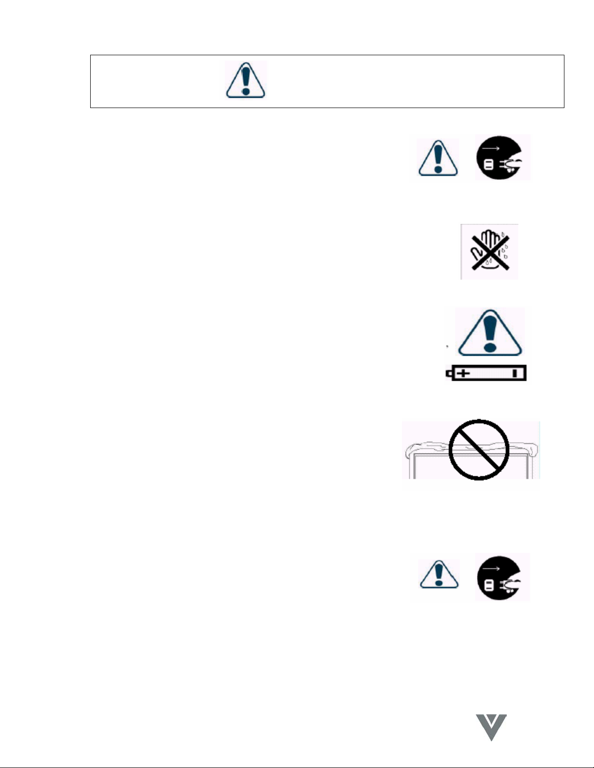
The User Manual uses the following symbols to ensure safe operation and prevent user
injury or property damage:
WARNING - Disregarding or inappropriate use may cause damage
to the product.
ATTENTION - Disregarding or inappropriate use may cause injury to
the user.
Examples
Prohibition
Warning (Attention) symbol (indicating "Electric Shock").
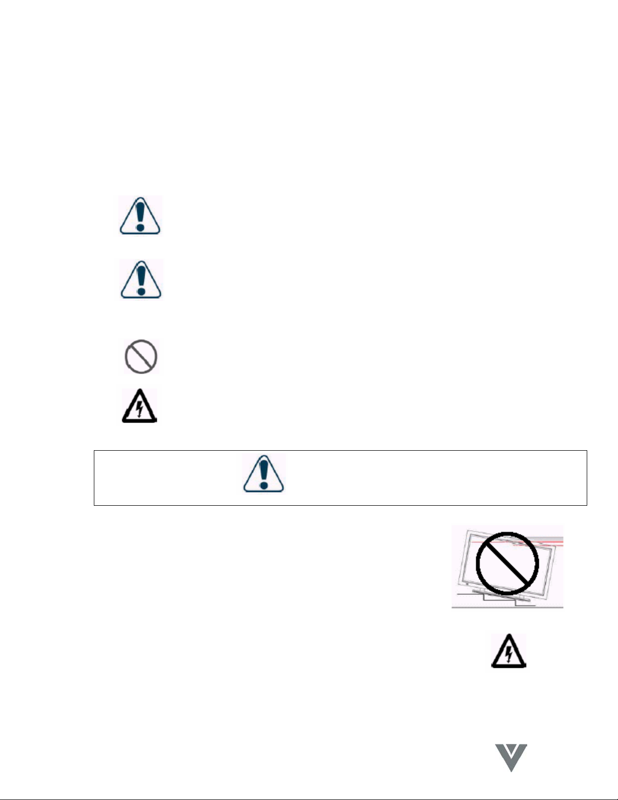
WARNING
Do not install the product on sloping or unstable surfaces
The product may fall over and incur damage or cause injury.
Only the marked power source can be used for the product
Any power source other than the specified one may cause fire or
electric shock.
6
VINC.COM
Page 8
VIZIO P4 User Guide
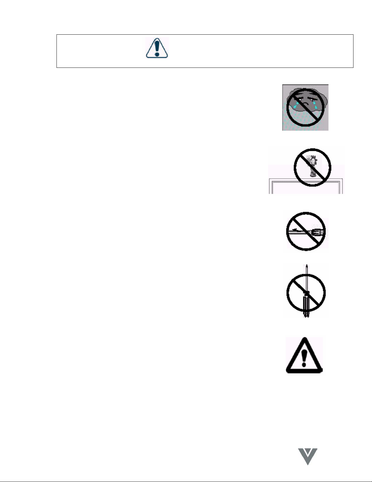
WARNING
Keep the product away from moisture
Do not expose this appliance to rain or moisture.
If water penetrates into the product, unplug the power cord and
contact with your dealer. Continuous use in this case may result
in fire or electric shock.
Do not place any objects on the top of the product
Spilled water or metal objects may cause short circuit, fire or
electric shock if they penetrate into the housing of the product.
Never use a damaged power cord
Heavy objects, heat or tensile force may damage the power cord
and cause fire or electric shock.
Do not modify or open the back cover
Removing the back cover of the product may cause fire or electric
shock.
Contact the manufacturer when inspection or adjustment is
required.
Do not use the product if any abnormality occurs
If any smoke or odor becomes apparent, unplug the power cord
and contact dealer immediately. Do not try to repair the product
yourself.
7
VINC.COM
Page 9
VIZIO P4 User Guide
WARNING
Avoid using dropped or damaged appliances
If the product is dropped and the housing is damaged, the internal
components may function abnormally. Unplug the power cord
immediately and contact dealer for repair. Continued use of the
product may cause fire or electric shock
Do not touch the power cord during lightning
To avoid electric shock, avoid handling the power cord
during electrical storms.
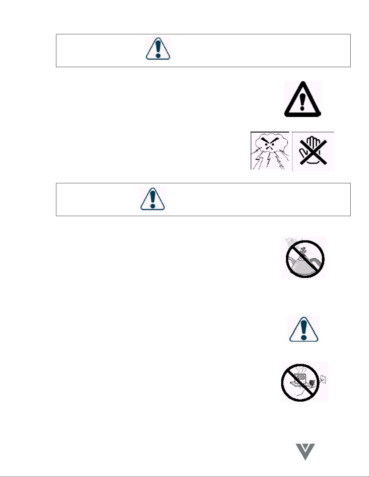
ATTENTION
Do not install the product close to smoke or moisture
Operating the product close to smoke or moisture may cause fire
or electric shock.
Do not install the product in an area with heavy dust or high
humidity
Operating the product in environments with heavy dust or high
humidity may cause fire or electric shock.
Instructions for moving the product
Ensure that the power connector and any other cables are
unplugged before moving the product.
The power cable should be kept away from heat sources
Heat sources may melt the covering of the power cable, causing
fire or electric shock.
8
VINC.COM
Page 10
VIZIO P4 User Guide
ATTENTION
Hold the power connector when removing the power
cable
Pulling the power cable itself may damage the wires inside
the cable and cause fire or electric shock.
Do not touch the connector with wet hands
To avoid risk of electric shock.
Insert batteries in accordance with instructions
Insert the batteries with correct polarities (positive + and negative
-). Incorrect polarities may cause damage and leakage of the
batteries, operator injury and contamination the remote controller.
Do not block or cover the vents
Blocking the vents may cause overheating and fire.
Do not install the product in a place with little or no
ventilation. Never cover the vents with towels, blankets or
dusters.
Unplug the connector
Unplug the power connector when the product will not be
used for an extended period of time.
9
VINC.COM
Page 11
VIZIO P4 User Guide
ATTENTION
Image Sticking
The plasma monitor illuminates phosphors to display images. The phosphor has a finite
illumination life. After extended periods of illumination, the brightness of the phosphor will
be degraded to such an extent that stationary images would burn-in that part of the
screen as grayed-out images.
Tips to prevent such image sticking are:
*Do not display images having sharp brightness differences or hi-contrast images, such
as monochrome characters and graphic patterns for extended periods.
*Do not leave stationary images for extended periods, but try to refresh them at
appropriate intervals, or try to move them using the screen saver function.
*Turn down the contrast and brightness levels.
NOTE: Such "Image Sticking" constitutes misuse and is NOT COVERED by the
manufacturer's warranty.
10
VINC.COM
Page 12

VIZIO P4 User Guide
11
VINC.COM
Page 13

VIZIO P4 User Guide
4. Product Features
The 46" PDP provides quality image displays and is suitable for a variety of multimedia
applications.
4.1 Available input signals
• The standard PC module provides RGB (D-SUB15 PIN) and digital DVI input
connectors, and a RS-232 communication connector (D-SUB 9 PIN MALE).
• The Video + Tuner module provides composite video (RCA), S-video (DIN4P)
and component video (RCA) input connectors, and a composite video (BNC)
output connector. It supports the quality input images of DVD and HDTV
(480P/720P/1080i), as well as the images of TV systems such as NTSC, PAL
and SECAM. The Video module also provides two sets of stereo audio input
connectors (RCA).
• The product supports PC image resolutions up to XGA (1024X768) with a vertical
frequency of 85Hz.
4.2 Power Management Function
The display can switch to a power saving mode using the PC input.
4.3 Fan-free Design
The unit does not require any fans for ventilation, providing quiet operation and
lower power consumption.
4.4 Other Features
• PIP Function: The user may watch video while working on their PC.
• The product includes a set of built-in 2W loudspeakers or can be connected to
two external 10W speakers.
• The Display provides High, Medium and Low color temperature options. The user
may also set a custom color temperature to suit individual preference.
12
VINC.COM
Page 14
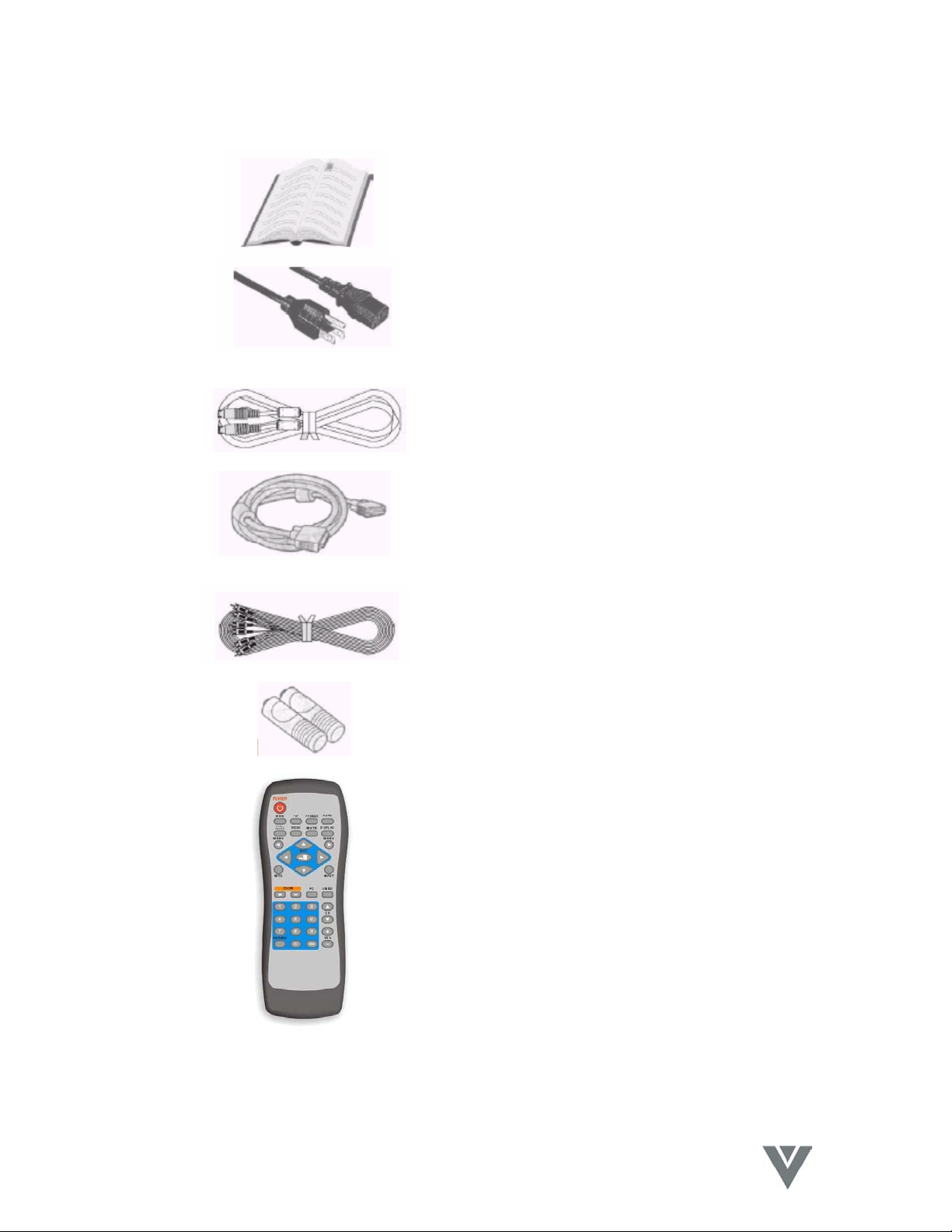
5. Standard Accessories
VIZIO P4 User Guide
This User Manual x1
Power Cord x1
S-Video Cable x1
15-Pin D-Sub Cable x1
AV Cable x1
AA Battery x2
Remote Control x1
NOTE: The style of the Remote Control
included with the Display may not be
identical to the one pictured.
13
VINC.COM
Page 15
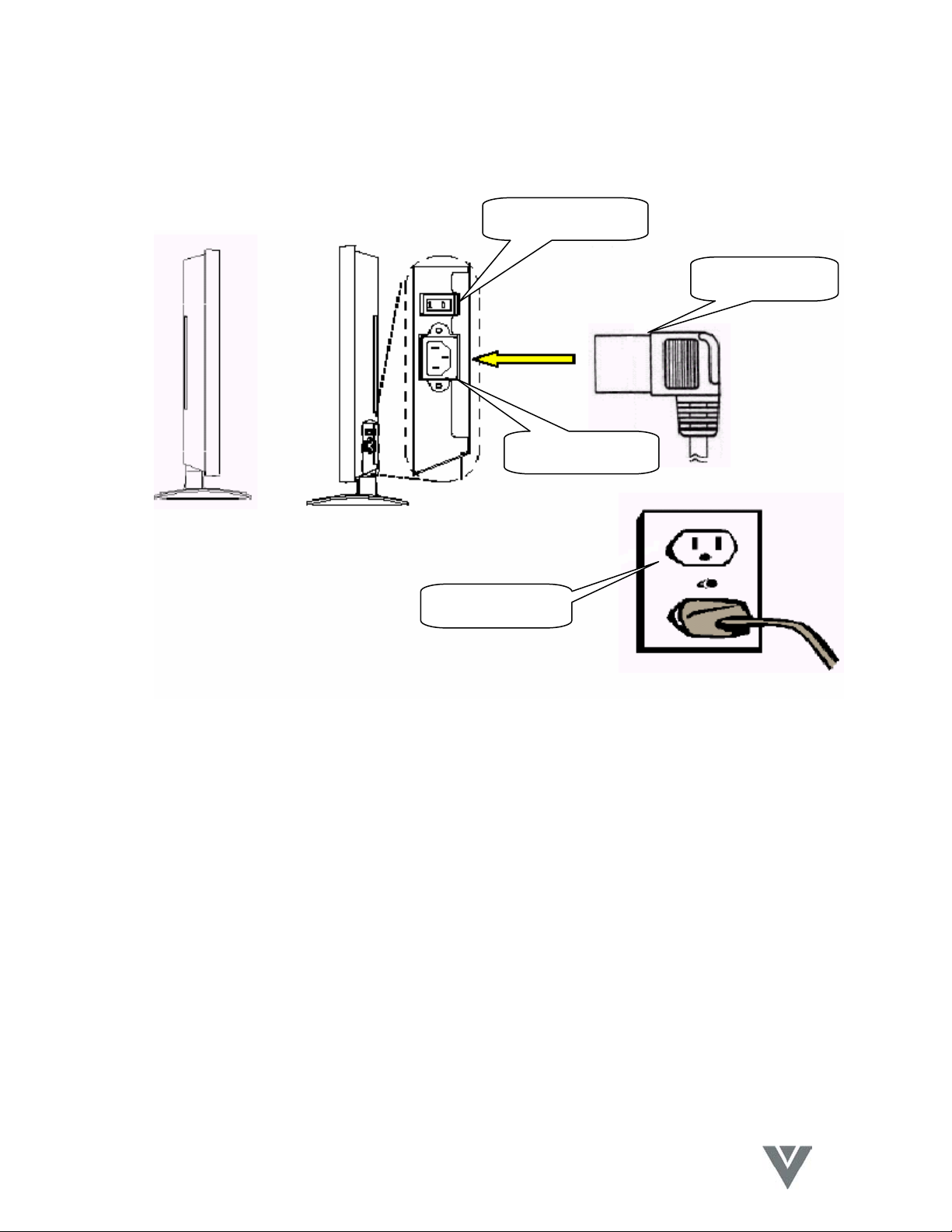
6. Names and Functions of Parts
6.1 Side View
Power Switch
VIZIO P4 User Guide
Power Cable
AC Connector
Power Outlet
• Connect the power cable female end to the display, then connect the male plug
to the wall outlet. Note: Male plug types vary among countries. The power plug
shown above may vary from the type supplied with your product.
• Push the power switch (0: Off, I: On) to the I (On) position. The power indicator
on the front panel will glow red, indicating that the plasma is in standby mode.
14
VINC.COM
Page 16

VIZIO P4 User Guide
6.2 Front View
(1) (2)
(1) Remote Control Window
The window includes the power indicator and the IR remote control sensor. LED's
are used to indicate the power status and the receiving of remote control signals.
Indicator ON (red) Standby mode.
Indicator ON (green) Power ON mode.
Indicator flashing (red/green) alternately Power Saving mode.
(2) Buttons
The functions of the buttons are described as follows:
• INPUT: Selects the signal inputs in the following sequence,
RGB1DRGB2DAV1DS-VideoDYCbCr/PbPrDTV/CATV (displayed sequentially).
Note: This button can display the input selection as an OSD so that the signal sources
may be chosen with the c/d buttons and selected with the f button.
• MENU: Activates the OSD Menu and selects an OSD Menu page; the pages
appear in the following sequence,
DisplayDImage (PC Input) or AV System (Video Input) DAudioDLanguage D
Screen SaverDMiscellaneousDStatus (displayed sequentially)
• c/d: A – Used as Up/Down buttons in the OSD Menu screen.
15
VINC.COM
Page 17
VIZIO P4 User Guide
B – Used for quick adjustment when the OSD Menu is not displayed on
the screen. The selections appear in the following sequence,
BalanceDBassDTrebleDVolumeDPIP Source*DContrast*DBrightness*
(sequential display). The adjustments are made in conjunction with the e/f
buttons.
*Note: The PIP source is only for the PC Input and the Contrast and Brightness are only
for the Video Input.
• e/f: A – Used as Left/Right buttons in the OSD Menu screen.
The f button also functions as Enter.
B – Used for the adjustment of Volume when the OSD Menu is not
active on the screen. Press e to reduce the volume, press f to
increase the volume.
• STANBY/ON: Is used to activate the Display or return it to Standby mode.
is the trademark of SRS Labs, Inc.
Licensed from SRS Labs, Inc.
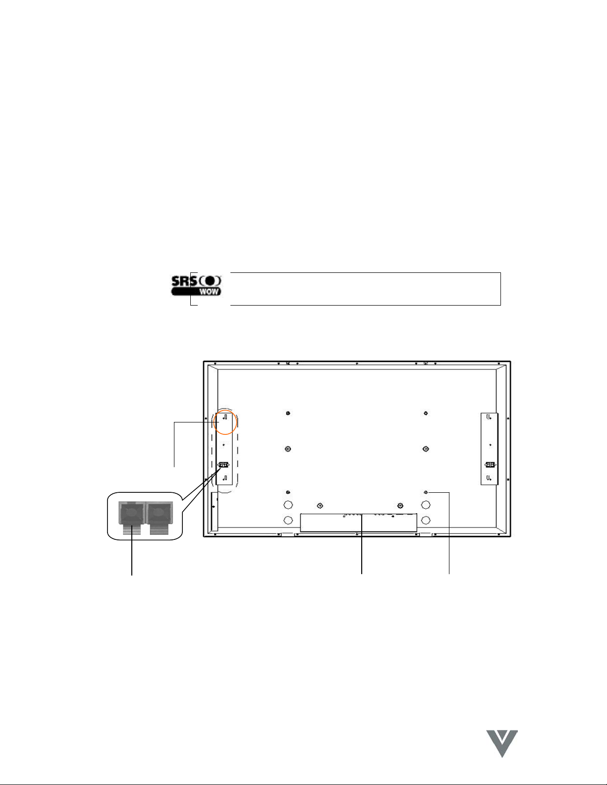
6.3 Rear View
(3)
(1) (4) (2)
(1) Speaker Terminals:
Can be used to connect external speakers to the Display. Maximum power output
10W (each) into 8 Ohm impedance.
(2) Wall Mount attachment holes:
Use the standard screws to attach the wall mount (optional accessory).
16
VINC.COM
Page 18
(3) Speaker Mounting Holes:
Use the brackets and screws supplied with the optional speakers to attach them to
the product.
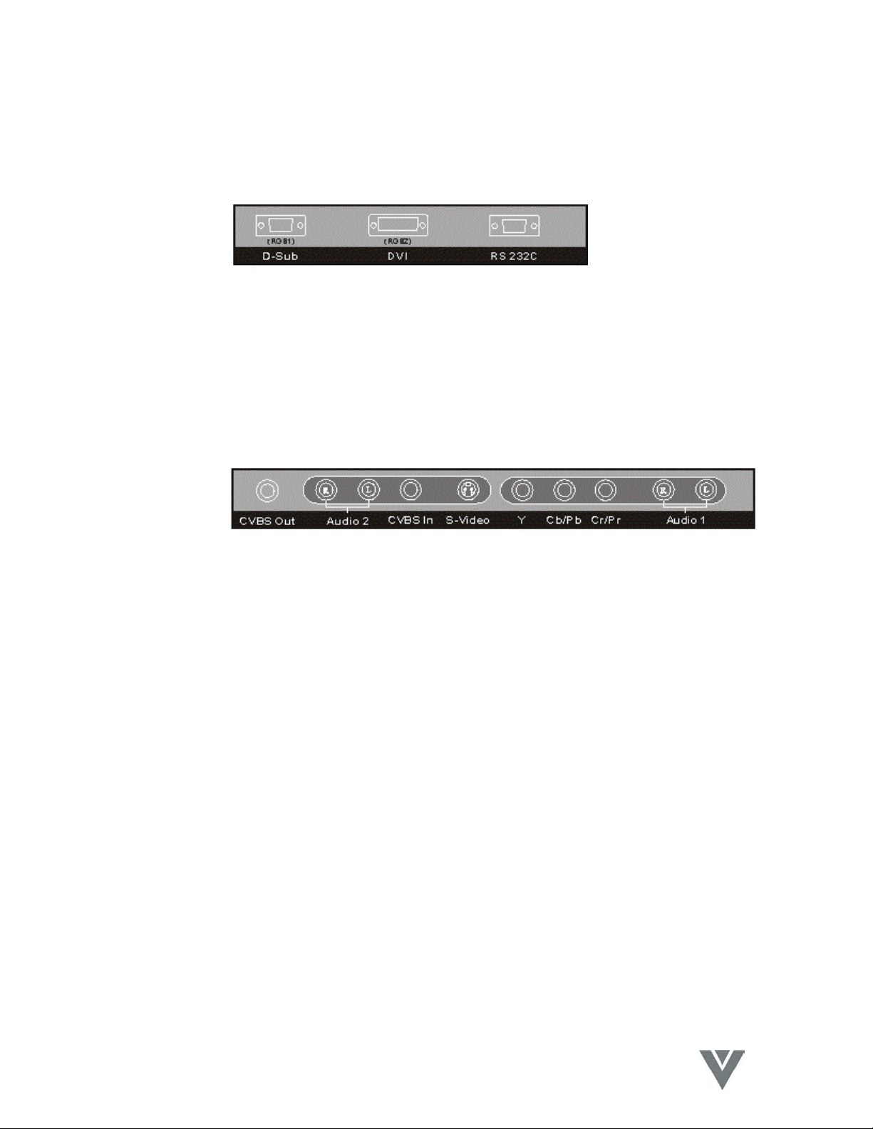
(4) Signal Input Connectors:
• PC Module
i. D-Sub: For PC display purposes. Connects to the 15-Pin D-Sub
ii. DVI: For high quality PC display purposes. Connects to the
iii. RS-232C: is a 9-Pin D-Sub male connector used as a control port
• Video Module
i. CVBS Out: Is a Composite Video output (BNC) connector for connection
ii. Audio 2: Are Audio input (RCA) connectors for connection to the
iii. CVBS In: Is a Composite Video input (RCA) connector for connection
iv. S-Video: Is a Y/C S-Video input (4-Pin DIN) connector for connection
v. YCbCr/PbPr: Are Component Video input (RCA) connectors for
connection to the Component outputs of the Video source.
vi. Audio 1: Are Audio input (RCA) connectors for connection to the
VIZIO P4 User Guide
analog output connector of the PC.
DVI-I digital output connector of the PC.
for serial communication between a PC and the Display.
to other displays.
Audio output of the associated Video source. CVBS In and SVideo share this Audio input pair.
to a Composite Video source.
to a S-Video source.
Audio output of the associated Video source. The Component
Video and PC Input sources share this Audio input pair.
17
VINC.COM
Page 19
VIZIO P4 User Guide
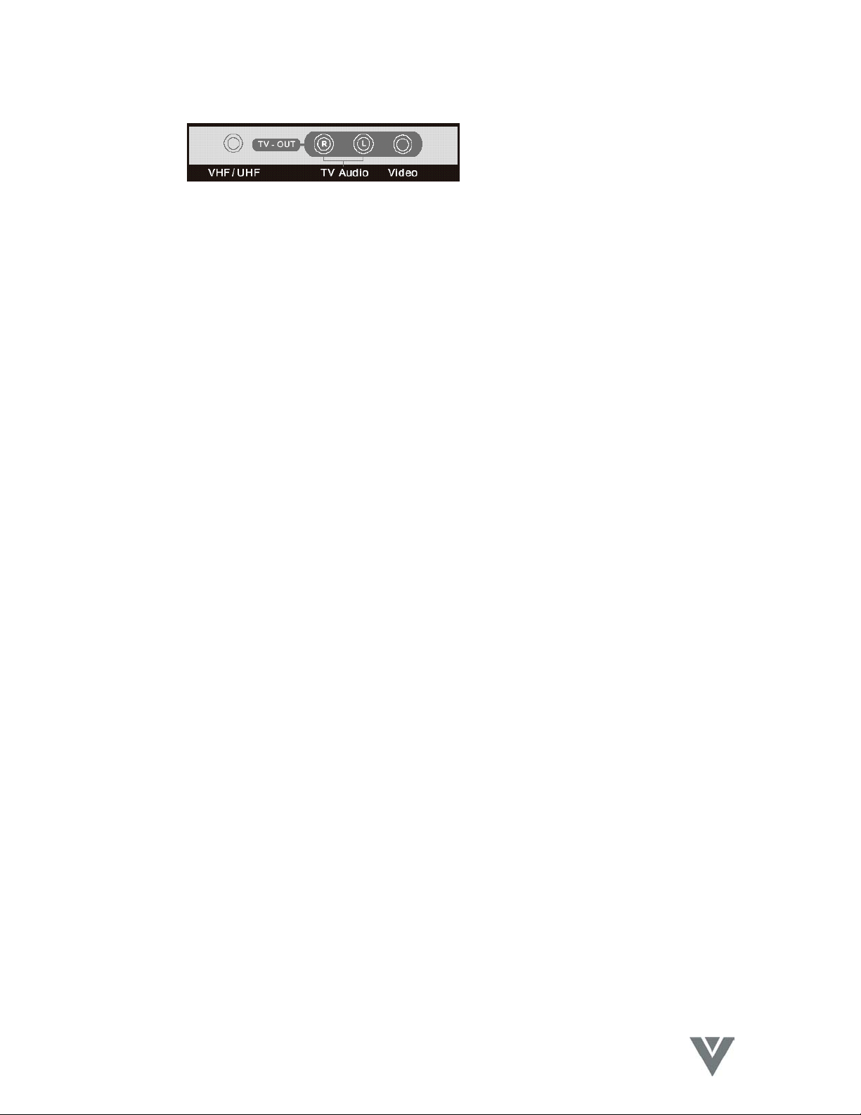
• Tuner Module
• The VHF/UHF Input can be connected to receive a TV/CATV signal from an
antenna or CATV 75Ω coaxial cable.
• The TV Audio Output can be connected to an Audio Amplifier or other TV Audio
Line Input.
• The Video Output can be connected to a Monitor or other TV with a Composite
Video Input.
18
VINC.COM
Page 20

6.4 Remote Control
VIZIO P4 User Guide
19
VINC.COM
Page 21

VIZIO P4 User Guide
6.4.1 Key Functions
(1) POWER
Press this key to turn the Plasma Display On from Standby mode. Press it
again to return to the Standby mode.
(2) VIDEO
Press this key to switch the Video input. The signal sources are selected in
the following sequence: AV1DS-VideoDYCbCr/PbPr.
(3) AUTO
Vertical and Horizontal position are adjusted automatically when pressing
this key in the PC mode.
B: The appropriate video format is chosen automatically when pressing this
key in the Video mode.
(4) PC
Press this key to select the PC input. The signal sources are selected in the
following sequence, RGB 1 (PC Module D-Sub Terminal) DRGB 2 (PC
Module DVI Terminal).
(5) MENUe and MENUf
Select OSD menu pages in the following sequence,
f f f f f f
DisplayDImage or AV SystemDAudioDLanguage & Screen SaverDMiscDStatus
e e e e e e
(6) INPUT
Press this key to select the signal sources directly.
RGB1DRGB2DAV1DS-VideoDYCpCr/PbPrDTV/CATV(sequential
display).
(7) WIDE
Press this key to switch to wide screen. Pressing this key again will restore
the original size of the screen.
(8) EXIT
Press this key to exit the OSD Menu.
(9) e and f
Use these keys to increase or decrease the value of the selected function.
(10) c and d
Use these keys to scroll in the OSD Menu, or to select a function in the
Quick Menu.
(11) ZOOM+ and ZOOM –
Use these keys to zoom the image in or out.
(12) VOL + and VOL –
Press the volume keys to increase or decrease the sound level.
(13) PIP
20
VINC.COM
Page 22

Use this key to activate and adjust the size of the picture-in-picture in the
following sequence,
Picture-in-Picture On-SmallDMediumDLargeDPicture-in-Picture Off
(sequential display).
(14) FREEZE
Press this key to "Freeze-Frame" the current screen. You may press this
key again to continue playing or play will resume automatically after one
minute.
(15) MUTE
Press this key to mute the sound. Press it again to reactivate the sound.
The sound is also reactivated if the power is turned off then on, or if the
volume level is changed.
(16) DISPLAY
Turns the Image and system information display On or Off.
(17) WOW
Press this key to turn the SRS Surround Sound feature On or Off.
(18) FULL WHITE
Displays a full white screen. This can be used to reduce image sticking
after displaying a static picture for an extended period. (Refer to Page 7)
(19) MTS
Press this key to select Stereo, SAP or Mono audio. This function is
available in the TV mode.
(20) Number Keys
TV direct channel selection.
CH c and CH d: Use these buttons to step up or down through the
available TV channels.
RETURN: Jumps to the last channel viewed.
Note: The Remote Control layout is for reference only.
VIZIO P4 User Guide
21
VINC.COM
Page 23

VIZIO P4 User Guide
6.4.2 Insertion of Batteries in the Remote Control
(1) As shown in the figure above, turn the Remote Control upside down, press and slide
off the battery cover.
(2) Insert two AA batteries in the remote control as shown in the figure above. (Polarity
+ or - must match the markings in the compartment).
(3) Replace the cover and slide in reverse until the lock snaps.
22
VINC.COM
Page 24

6.4.3 Remote Control Range
VIZIO P4 User Guide
• Point the Remote Control at the receiver window (the window through which the
power LED is illuminating) to transmit the commands.
• Do not place any obstacles between the Remote Control and the receiver
window.
• The effective range of the Remote Control is approximately 32 feet (10 meters)
from the front of the receiver window, 30º to the left and right, 20º up and down.
6.4.4 Using the Remote Control
i. Do not subject the Remote Control to undue physical stress, such as striking
or dropping it. It should be kept dry and away from heat sources.
ii. Do not attempt to clean the Remote Control with a volatile solvent. Wipe it
with a clean, damp cloth.
iii. If the display responds erratically to the Remote Control, or does not respond
at all, check the batteries. If they are low or exhausted, replace them with
fresh batteries.
23
VINC.COM
Page 25

7. Connection to External Equipment
7.1 Connection to Antenna
VIZIO P4 User Guide
• When using a 75Ω Coaxial Cable it can be connected directly to the VHF/UHF
terminal of the tuner.
VHF/
UHF
• When using a 300Ω parallel feed line it must be connected to a 300Ω to 75Ω
converter and then connected to the VHF/UHF terminal of the tuner.
24
VINC.COM
Page 26

7.2 PC Module
VIZIO P4 User Guide
• For operating the Display as a PC monitor.
15-Pin D-Sub connects to analog RGB output interface (Input option RGB1).
DVI connects to digital RGB output interface (Input option RGB2).
Note 1: The DVI connector of the Display is DVI-D, which does not support analog
inputs.
Note 2: The RS-232 connector of the Display provides a transmission interface for
professional technicians to update firmware and does not provide additional
communication functions.
25
VINC.COM
Page 27

VIZIO P4 User Guide
7.3 PC Module + Video Module
• The functions of D-Sub, DVI and RS-232 terminals are the same as for the PC
module.
• The Component connectors (Y/PbCb/PrCr) accept the component output of a
video device (such as a DVD or HDTV Receiver). The audio input is via Audio 1
(INPUT Option YCbCr/PbPr).
• The S-Video connector accepts the Y/C S-Video output of a video device (such
as an S-VHS or DVD). The audio input is via Audio 2 (INPUT Option S-Video).
• The CVBS In connector accepts the CVBS (Video) output of a video device (such
as a VHS, S-VHS or DVD). The audio input is via Audio 2 (INPUT Option AV1).
• The S-Video and CVBS inputs share the Audio2 input.
26
VINC.COM
Page 28

VIZIO P4 User Guide
• The CVBS Out (BNC) connector can be used to connect the Display to another
TV or display, transmitting the signal input via CVBS to the other display.
7.4 Connection to External Speakers
SPEAKER (OPTIONAL)
SPEAKER
WIRE
SPEAKER
PDP REAR VIEW
SPEAKER
WIRE
• Press the spring-loaded terminals and insert the speaker wires, making sure that
the copper is making good contact with the metal terminal and the colors of the
wire match those on the terminal (red to red and black to black). Release the
terminals to clamp the speaker wires in place.
Note 1: When connecting the external speakers, remember to set the speaker output
to External mode on the Audio page of the OSD Menu. (Refer to 8.7.2.)
Note 2: Please use the wires enclosed with the external speakers, to ensure
electromagnetic interference is minimized.
27
VINC.COM
Page 29

8. Basic Operation
8.1 Power On / Off
VIZIO P4 User Guide
• Press the POWER key to turn on the Display. The power
indicator will change from red to green.
• Press the POWER key again to return the Display to
Standby mode. The power indicator will change from green
to red.
Note: The power indicator will flash for a few seconds before
changing color.
8.2 Input Mode Selection
• Press the INPUT key. A menu of input signal sources will
appear on-screen. Use the c/d keys to select the signal
source desired and press the f key to confirm the selection.
• You may also press the INPUT key repeatedly until the
signal source you want is highlighted. The signal sources
are displayed in the following sequence,
RGB1DRGB2DAV1DS-VideoDYCbCr/PbPrDTV/CATV
RGB1 = Analog D-Sub input on the PC Module.
RGB2 = Digital DVI-D input on the PC Module.
28
VINC.COM
Page 30

8.2.1 Selection of TV Mode
Select the TV Input by one of three methods:
• Press the INPUT key. A menu of
input signal sources will appear
on-screen as shown in the
picture opposite. Use the c/d
keys to select the signal source
desired and press the f key to
confirm the selection.
• Press the VIDEO key repeatedly to select a signal source
from the Video module. The signal sources are displayed in
the following sequence,
AV1DS-VideoDYCbCr/PbPrDTV/CATV
• The Display will search for the TV/CATV signal automatically
if there is no other input.
8.2.2 Selection of Video Input Mode
VIZIO P4 User Guide
• Press the VIDEO key repeatedly to select a signal source
from the Video module. The signal sources are displayed in
the following sequence,
AV1DS-VideoDYCbCr/PbPrDTV/CATV
29
VINC.COM
Page 31

8.2.3 Selection of PC Input Mode
• Press the PC key repeatedly to select a signal source from
VIZIO P4 User Guide
the PC module. The signal sources are displayed in the
following sequence,
RGB1DRGB2
RGB1 = Analog D-Sub input on PC Module.
RGB2 = Digital DVI-D input on PC Module.
30
VINC.COM
Page 32

8.3 OSD Option Adjustment
• The keys for OSD option adjustment include: MENUe,
MENUf, c, d, e, f and EXIT.
• Press MENUe, MENUf to display the OSD Menu then
press again to highlight a submenu, scrolling left or right.
The pages are displayed in the following sequence
(sequential display),
MENUfDMENUf DMENUfDMENUf DMENUfDMENUf
Display DImage or AV SystemDAudio DLanguage &DMisc DStatus
Screen Saver
MENUeCMENUe CMENUeCMENUe CMENUeCMENUe
• Use the c/d buttons to select a function within the selected
menu, scrolling up or down, or to select an item from the
Quick Menu.
The Quick Menu display sequence is as follows,
BalanceDBassDTrebleDVolumeDPIP Source*DContrast*DBrightness*
(sequential display).
*Note: The PIP source is only for the PC Input and the Contrast and
Brightness are only for the Video Input.
VIZIO P4 User Guide
• Use the e/f buttons to adjust the selected function.
Use these buttons to increase or decrease the value. The
right f button functions as Enter where applicable (indicated
at the bottom of the OSD).
• Press the EXIT button to exit the OSD Menu.
Note: The OSD timeout can be set on the Miscellaneous Menu. If no
button is pressed within the set time, the system exits the OSD
Menu automatically.
31
VINC.COM
Page 33

8.4 Sound Adjustment
• Press and hold VOL + to increase the sound volume level
• Press the MUTE button to mute the internal or external
• Other audio adjustments (such as treble, bass and balance)
VIZIO P4 User Guide
and press and hold VOL - to decrease the sound volume
level.
speakers. Press the MUTE button again to restore the
sound at the previous volume levels.
can be adjusted on the OSD Menu or Quick Menu.
8.5 Zoom Functions
• The Zoom buttons include WIDE, ZOOM+ and ZOOM-.
• By pressing the WIDE button, you can zoom in on the image
to fill the screen. You can then restore the image to its
original size by pressing the WIDE button again.
Note: 1. With PC input, you can switch between the full screen
size and the original signal format.
2 When a video signal is selected, you can switch
among six screen sizes, including Full, Fill Aspect
Ratio, 4:3 to 16:9, LB to 16:9, LB Subtitles to 16:9 and
Anamorphic. (LB=Letter Box.)
• By pressing and holding the ZOOM+ button, you can zoom
the image gradually. By pressing and holding the ZOOM-
button, you can zoom out of the image gradually. Pressing
the EXIT button will also restore the image to its original
size.
Note: 1. You can only zoom the image out to its original size
by pressing the ZOOM- button. The image cannot be
made any smaller with this function.
2 When the image is zoomed in by using the ZOOM+
button, you can use c, d, e and f keys to scroll the
image within the viewing area.
32
VINC.COM
Page 34

8.6 Other Functions
VIZIO P4 User Guide
• If an image cannot be displayed after changing the timing in
PC mode, press the AUTO button. The unit will
automatically adjust the Phase, Horizontal and Vertical
position to optimize the display.
• If the image cannot be displayed after changing the playback
system in Video Input mode, press the AUTO button. The
unit will select the appropriate format for the image system.
Note: For the information about the timing capabilities of the
unit, refer to Chapter 11.
• Press the FREEZE button to freeze the current screen.
Press the FREEZE button again to return to a live picture.
Note: You can only freeze the screen by pressing the FREEZE
button. The playback system keeps playing when the
screen is frozen.
• Press the PIP key to show the Picture-In-Picture screen. The
screen will change as follows when you press the PIP key
consecutively,
Picture-in-Picture On-SmallDMediumDLargeDPicture-in-Picture Off
Note: The Picture-In-Picture screen can receive video images
while the PC outputs the display to the Main Screen, so
the prerequisites for the display of the sub-picture
include,
1. A video module installed.
2. The Main Screen must be a PC display.
3. The video image source must also be connected.
• The location of the sub-picture on the screen and the video
image source can be set from the OSD menu.
33
VINC.COM
Page 35

VIZIO P4 User Guide
8.7 OSD Functions
8.7.1 General Description of the OSD Function Pages
• PC
Display
(DVI input)
Brightness H. Position Volume Language OSD Position Resolution
Contrast V. Position Treble Image Reverse OSD Timeout V. Frequency
Red1 Phase Adj. Bass Image Move OSD Rotation H. Frequency
Green1 Sync Adj. Balance Move Time Color Temp. PP Input
Blue1 Aspect Ratio Mute WOW Reset to default PIP System
Reset Reset DPMS Speaker Advanced Mode PIP Settings
Gamma
Color Space
PC User
• PIP Setting
Display
(Analog input)
Image Audio Language &
Display Miscellaneous
Brightness PIP Size
Contrast PIP Source
Saturation PIP Position
Reset
Miscellaneous Status
Screen Saver
• Video + Tuner
Display AV System Audio Language & Screen Saver Miscellaneous Status
Brightness TV Function Volume Language OSD Position Input Source
Contrast Aspect Ratio Treble Image Reverse OSD Timeout System
Saturation Video Format Bass Image Move OSD Rotation
Hue²
Sharpness Mute WOW Reset to Default
Rest Speaker Advanced Mode
Gamma
Color Space
Balance Move Time Color Temp.
User Color Temp
³
• User Color Temp³
Display
Red
Green
Blue
Note: The adjustable items vary depending on the input source.
1
When USER is selected from Color Temp. preset.
2
Hue has no effect when using YCbCr/PbPr.
3
Press the EXIT key to return to the Main Menu.
34
VINC.COM
Page 36

VIZIO P4 User Guide
8.7.2 OSD Menus and Functions
8.7.2.1 Display Menu
PC VIDEO
• Only the Brightness, Contrast and Reset functions can be adjusted when using an analog
PC input signal. The brightness of the Red, Green and Blue can be adjusted when User
Color Temp is selected from the Miscellaneous Menu.
• The Brightness, Contrast, Saturation, Hue, Sharpness and Reset can all be adjusted when
using Video input signals.
• When YCbCr/PbPr video is the primary source, Hue and Sharpness are not available.
When YCbCr/PbPr is selected as a PIP source, Hue has no effect on the PIP image.
8.7.2.2 Image and AV System Menu
PC VIDEO
• With PC input signals, the Horizontal Position, Vertical Position, Phase, Sync and Aspect
Ratio can be adjusted, and DPMS can be enabled or disabled.
• With a video signal you can adjust the TV Function, the Aspect Ratio and select the Video
(signal) Format you want. If you do not know which Video format to select, choose Auto
and the display will select the correct signal automatically.
• The Display provides six aspect ratio formats in the Video input modes, and two in the PC
input modes. You can select the most suitable format for the selected signal source. Press
the on the remote control or the Display to select Full, Fill Aspect Ratio, 4:3 to 16:9, LB to
16:9, LB Subtitles to 16:9 or Anamorphic aspect ratios.
35
VINC.COM
Page 37

VIZIO P4 User Guide
8.7.2.3 Channel Scan and Memory
• Highlight the TV Function and then
press
option.
• Press the c or d key to highlight
Source and then repeatedly press
the f key to cycle through
Antenna, CATV (STD, IRC, or
HRC) and select the one that
matches the broadcasting system
you are receiving.
• Now press
Program and then press the f key to commence
Channel Scan to automatically find and
memorize the channels available. During this
process all other functions will be disabled and
the OSD icon shown in the picture opposite will
be displayed.
Once this process has been completed the channels stored in memory may be
•
selected sequentially by pressing the CHc and CHd keys or directly by pressing
the number keys on the Remote Control.
and f key to select thus
the c key to highlight Channel
36
VINC.COM
Page 38

VIZIO P4 User Guide
8.7.2.4 Audio Menu
• The adjustable items on the Audio Menu are Volume, Treble, Bass, Balance and Mute.
These items are the same for both PC and Video signals. Internal or External speakers can
also be selected from this menu.
8.7.2.5 Language and Screen Saver Menu
PC Options in Advanced Mode
VIDEO Options in Advanced Mode
• You can select the languages provided by OSD from the Language option.
• When a static image is being displayed on the screen for a long period of time, use the Image
Reverse or Image Move features to prevent screen burn and protect your screen. The Move Time
function allows you to adjust the time between the stages of the Image Move feature.
37
VINC.COM
Page 39

VIZIO P4 User Guide
8.7.2.6 Miscellaneous Menu
PC VIDEO
• The OSD Position and OSD Timeout options allow you to select the location of the OSD on
the screen and the length of time that OSD will remain on screen. The OSD Rotation
option allows you to rotate the OSD 90° CCW.
• The PIP Settings option can be accessed when the input signal is from a PC (Note: The
Video, S-Video or Component input must have an input signal in order to use this option).
• Your preferred screen color temperature can be selected from the Color Temp. option. You
can choose from Warm, Standard, Cool or User. By selecting User, you can then adjust the
brightness of Red, Green and Blue individually in order to adjust the white point to suit your
preference, by making the adjustments in the Display Menu. Note: Only User Color
Temperature is adjustable. The Warm, Standard and Cool settings are preset at the factory.
8.7.2.6.1 PIP Setting (for PC Mode only)
• To access these options, select PIP Settings from the Miscellaneous menu.
• The Display menu is the same as the Display menu in Video mode. The Image menu is
used to enable and disable the PIP, set the PIP size and select the PIP source and position.
• Press the Exit key to exit the PIP Settings sub-menu and return to the Main Menus.
38
VINC.COM
Page 40

VIZIO P4 User Guide
8.7.2.6.2 PIP Setting with Tuner (for PC Mode only)
• The TV Function selection has the same effect as this selection in the Image and AV
System Menu in section 8.7.2.3
• Press
(when OSD is not being displayed)
the c/d keys to enter the Quick Menu to select TV for the PIP Source.
39
VINC.COM
Page 41

VIZIO P4 User Guide
8.7.2.6.3 User Color Temp. Menu (for AV Mode only)
• To access these options, select the User Color Temp. option on the Miscellaneous menu.
You can adjust the brightness of Red, Green and Blue to suit your personal preference for
white point. Note: Only User Color Temperature is adjustable. The Warm, Standard and
Cool settings are preset at the factory.
8.7.2.7 Status Menu
PC VIDEO
• This menu displays the Resolution, Vertical Frequency and Horizontal Frequency when a
PC input is operating. If PIP is in use, the sub-picture source and system are also
displayed.
• The Input source and System are displayed when using video signals.
40
VINC.COM
Page 42

VIZIO P4 User Guide
8.7.2.8 CC and Parental Control Menus
• Select the TV Function on the Image
and AV System Menu. Press the f
key to select the TV Function Menu.
Pressing the
the CC and Parental Control Menu.
(See section 8.7.2.9)
• Select the Channel Program function
and press the f key to perform
Channel Scan and Addressing.
• Select the Source function and press
the e/f keys to select the TV/CATV
system. You must select the
broadcasting system before
the Channel Program function
• The MTS Select function allows you to
choose from Stereo, Sap and Mono
using the e/f keys. (This same process can be achieved by using the MTS key on the
Remote Control.)
• Select the Channel function to Add or Erase Tuner Channels on the list used by the
Channel Up / Down keys.
• The Sleep Time can set for automatic power off of the Display. The number “0” means the
sleep timer is disabled.
MENUf key will recall
selecting
41
VINC.COM
Page 43

VIZIO P4 User Guide
8.7.2.9 CC and Parental Control Menu
• Select the TV Function on Image and AV System Menu. Press the f key to display the CC
and Parental Control Menu.
• Highlight the Close Caption function
and use the e/f keys to select the
options CC1, CC2, T1, T2, T3 and T4.
• The options are described below.
Option Description Option Description
CC1 Show the first Subtitle T1 Show the first Subtitle Message
CC2 Show the second Subtitle T2 Show the second Subtitle Message
T3 Show the third Subtitle Message
T4 Show the fourth Subtitle Message
OFF Turn off the Subtitle feature
• Highlight the Parent Control function and press the f
key to select the function.
• A message will show on the screen and will wait for you
to enter the password. The password has been set to
“1234” at the factory so if you are using this feature for
the first time you must use this number.
• If the password is correctly entered and accepted the
Parental Control / V-Chip Menu will be displayed. If it is
not accepted, check that the password was entered
correctly.
42
VINC.COM
Page 44

8.7.2.9.1 MPAA Rating
• Highlight the MPAA Rating item and
press the f key to select the
function.
• Press
the c/d keys to highlight
the rating items you want to set
and then press the e or f key to
Show or Block the selection.
• When an item is Blocked, all of the
higher ratings will also be blocked.
For example, if PG-13 is set to
Block, then ratings R, NC-17 and X
will be set to Block automatically.
• The MPAA Ratings are described
below.
VIZIO P4 User Guide
Rating Description
G General audience (appropriate for all ages).
PG Parental Guidance suggested (some material may not be suitable for children).
PG-13 Parents strongly cautioned (some material may be inappropriate for children
under 13 years of age).
R Restricted (persons under 17 years of age requires accompanying parent or
adult guardian).
NC-17 Not intended for any person 17 years of age or younger.
X X-rated (for adults only).
43
VINC.COM
Page 45

8.7.2.9.2 US TV Rating
• Highlight the US TV Rating item and
press the f key to select the function.
• Press
the c/d keys to highlight the
rating items you want to set and
then press the e or f key to Show
or Block the selection.
• When an item is Blocked, all of the
higher ratings will also be blocked.
For example, if TV-G is set to Block,
then ratings TV-PG, TV-14 and TV-
MA will be set to Block automatically.
• The US TV Ratings are described below.
VIZIO P4 User Guide
Rating FV
(Fantasy) V (Violence)
TV-Y (All children)
TV-Y7 (Children 7 years
old or younger)
TV-G (General audience)
TV-PG (Parental
guidance suggested)
TV-14 (Parents strongly
cautioned)
TV-MA (Mature audience
only)
X
X X X X
X X X X
X X X
S
(Sexual
situations)
Note: “X” indicates that the content rating can be set.
8.7.2.9.3 Canadian English Rating
• Highlight the Canadian English Rating
item and press the f key to select the
function.
• Press
the c/d keys to highlight the
rating items you want to set and
then press the
Block the selection.
e or f key to Show or
• The Canadian English Ratings are described below.
L
(Adult
language)
D
(Sexually
suggestive dialog)
44
VINC.COM
Page 46

Rating Description
E Exempt
C Children
C8+ Children 8 years old and older
G General programming, suitable for all audiences
PG Parental guidance
14+ Viewers 14 years old and older
18+ Adult programming
8.7.2.9.4 French Canadian Rating
• Highlight the Canadian France Rating
item and press the f key to select the
function.
• Press
the c/d keys to highlight the
rating items you want to set and
then press the e or f key to Show or
Block the selection.
• The French Canadian Ratings are
described below.
VIZIO P4 User Guide
Rating Description
E Exempt
C Children
8 ans + Children 8 years old and older
13 ans + Viewers 13 years old and older
16 ans + Viewers 16 years old and older
18 ans + Adult programming
45
VINC.COM
Page 47

9 Optional Accessories
d
Tilt Angle adjustable 0 - 20°
Wall Mount
Stand I
Stand II (refer to the stand assembly instruction)
Speakers I
VIZIO P4 User Guide
Fix the PDP Set to the Stan
Speakers II
Ceiling Mount
46
VINC.COM
Page 48

VIZIO P4 User Guide
10 Technical Specification
Screen Size 46-in, Wide Screen
Screen Area 39.7-in (1007mm) Wide x 22.3-in (567.4mm) High
Aspect Ratio 16:9
Overall Size 44.8-in (1138mm) Wide x 27.2-in (691mm) High x 3.8-in (98mm)
Deep, without Stand
Weight 82lbs (37kg), without Stand
Resolution 852 (H) x 480 (V) Pixels (Each pixel has R/G/B 3-color cells.)
Pixel (Dot) Pitch 1.182mm (H) x 1.182mm (V)
Color 16.7 million colors
Gray Scale 256 steps (8-bit addressing for each color Red, Green and Blue)
Brightness (Peak Value) 700 cd/m2 Typical (Panel Only)
Contrast (Dark Room) 800:1 Typical
Viewing Angle More than 160° horizontally and vertically
Sound SRS Sound
Power Input 100 ~ 120Vac/220 ~ 240Vac, 50 ~ 60Hz
Power Consumption 330W (Average)
Inputs PC Module
Analog RGB Input, 15-Pin D-Sub
Digital TMDS Input, DVI Connector
RS-232 Communication, 9-Pin D-Sub
Video Module
S-Video Input, mini 4-Pin DIN
CVBS (Composite) Input, RCA Phono
YCbCr/PbPr (Component) Input, RCA Phono
L+R Audio (x2) Inputs, RCA Phono (x4)
CVBS (Composite) Output, BNC
Enhanced PC Module
Analog RGB Input, 15-Pin D-Sub
Analog RGB Input, BNC (x5)
Analog RGB Output, 15-Pin D-Sub
PC Audio Input, 3.5mm Stereo Jack
Agency Certifications UL, CSA, FCC Class B
Standard Accessories Remote Control, AA Batteries (x2), Power Cord (NA), 15-Pin D-
Sub Cable, S-Video Cable, AV Cable, User Manual
47
VINC.COM
Page 49

VIZIO P4 User Guide
11 Factory Preset Timings
There are 17 different timing formats that are preset at the factory for the RGB Mode.
# Resolution Horizontal
Frequency (kHz)
1 720x400 31.47 70.08 25.17 DOS
2 640x400 37.90 85.00 31.50 VESA
3 640x480 31.50 60.00 25.18 DOS
4 640x480 35.00 67.00 30.24 Mac (SOG)
5 640x480 37.50 75.00 31.50 VESA
6 640x480 37.86 72.81 31.50 VESA
7 640x480 43.30 85.00 36.00 VESA
8 800x600 35.16 56.25 36.00 VESA
9 800x600 37.90 60.32 40.00 VESA
10 800x600 46.90 75.00 49.50 VESA
11 800x600 48.08 72.19 50.00 VESA
12 800x600 53.70 85.00 56.25 VESA
13 832x24 49.00 74.00 57.27 Mac (H+V)
14 1024x78 48.40 60.00 65.00 VESA
Vertical
Frequency (Hz)
Dot Clock
Frequency (MHz)
Remarks
15 1024x78 56.50 70.00 75.00 VESA
16 1024x78 60.00 75.00 78.75 VESA
17 1024x78 68.70 85.00 94.50 VESA
• When the signal received by the Display exceeds the allowed range, a warning
message "Signal Out Of Range" will appear on the screen.
• You can confirm the input signal format by selecting the Status page from the
OSD Menu.
48
VINC.COM
Page 50

VIZIO P4 User Guide
12 Cleaning and Simple Troubleshooting
12.1 Important
1. Make sure that the power cable is removed from the socket before cleaning the
Display.
2. Do not use volatile solvent (such as toluene, rosin and alcohol) to clean the
Display. Such chemicals may damage the housing, screen glass and remote
control, and cause the paint to peel.
12.2 Cleaning the Housing and the Remote Control
1. Use a soft cotton cloth for cleaning.
2. If the Housing or Remote Control are seriously contaminated, use a soft cloth
moistened with diluted neutral cleaner to clean the Display. Wring water out of the
cloth before cleaning to prevent water from penetrating into the housing. Wipe the
Display with a dry cloth after cleaning.
12.3 Cleaning the Screen
1. Use a soft cotton cloth to gently clean the screen.
2. The screen glass is very fragile. Do not scrape it with any sharp object. Do not
press or tap the screen to avoid cracking. When the screen is seriously
contaminated, use a soft cloth moistened with diluted neutral cleaner to clean the
Display. Wring water out of the cloth before cleaning to prevent water from
penetrating into the housing. Wipe the Display with a dry cloth after cleaning.
49
VINC.COM
Page 51

VIZIO P4 User Guide
12.4 Simple Troubleshooting
If the display fails or the performance changes dramatically, check the Display in accordance with the
following instructions. Remember to check the peripherals to pinpoint the source of the failure. If the
Display still fails to perform as expected, contact the dealer for assistance.
Problem Solution
Power cannot be turned on. (Power
indicator does not light)
"No Input Signal" message appears on the
screen.
Check that both ends of the power cable are plugged into
the socket appropriately.
− Check that the signal cable is connected properly.
− Check that the power of the relevant peripherals are
turned on.
− Check that the Input option that has been selected
matches with the input signal.
The remote control does not function
properly.
− Check that the polarity of the batteries are correct.
− Check that the batteries are not drained. (Use new
batteries.)
− Check that the Remote Control is within the operating
range.
− Check that the Remote Control is pointed at the Remote
Control Window on the Display.
− Check that there are no obstacles between the Remote
Control and the Remote Control Window.
− For more information about the Remote Control, refer to
Chapter 8.
Flashing spots or stripes appear on the
screen.
Check for possible interference sources such as a Car, HV
cable, Neon lamp, etc.
Image color or quality deteriorates. − Check that all the video settings are adjusted
appropriately, such as Brightness, Contrast, Color, etc.
− For more information about video settings, refer to OSD
Functions in Chapter 8.
Screen position and size are incorrect. Check that the screen position and size is adjusted
appropriately.
Image or color is incorrect. − Check that the signal cable is connected properly.
− When connecting to a PC, change the resolution of the
PC to acquire the correct image. The difference of the
PC output signal may affect the display of the image.
The external speaker has no sound. − Check that the speaker cables are connected
appropriately.
− Check that the external speakers are enabled in the
OSD
− For more information about audio settings, refer to OSD
Functions in Chapter 8.
The power indicator flashes − Check that the input signal cables are properly attached.
− Check that the display is not in the Power Save mode.
The input image and signal is not received
appropriately. "Signal Out of Range"
message appears on the screen.
− Select the correct input signal.
− For more information, refer to Factory Settings in
Chapter 11.
50
VINC.COM
Page 52

13. Optional Wall Mount Installation Instructions
VIZIO P4 User Guide
Read these instructions before attempting installation
SAFETY ADVISORY
13 The wall should be capable of supporting a weight of at least twice (2x) the weight of the
Plasma TV, and the site should be studied carefully for correct Stud (Wood), Stud (Metal), Drywall
and Concrete mounting procedures. For calculated weights of more than 160lbs, the wall or
ceiling must be reinforced. V, Inc strongly recommends that the installation, as outlined in these
installation instructions, is undertaken by qualified personnel who specialize in wall mount
installation and are familiar with installation of this type of material. Failure to do so could result in
serious personal injury. V, Inc is not liable for improper installation procedures that result in
damage to mounts, adapters, Plasma Televisions or personal injury as a result of improper
installation.
• Before Commencing Installation
Check that all of the parts listed below are in the package. If any parts are missing please contact V, Inc at 714-9624848 or http://www.vinc.com
13 ITEM 14 DESCRIPTION 15 QUANTITY
so that the missing parts(s) can be sent to you.
16 1 17 Plasma Brackets 18 1 Left, 1 Right
19 2 20 6x12mm Screws 21 8
22 3 23 Wall Plate 24 1
25 4 26 5/16” Lag Bolt 27 6
28 5 29 5/16” Flat Washer 30 6
31 6 32 ¼x20 Securing Knob 33 2
51
VINC.COM
Page 53

VIZIO P4 User Guide
Ventilation Requirements for Wall Mounting
To allow adequate ventilation for the Plasma TV use at least the minimum the space around the TV, as
shown on the diagram below, when installing the TV in the desired location.
52
VINC.COM
Page 54

VIZIO P4 User Guide
• Attach the Plasma Brackets to the Plasma TV
Carefully lay the display, screen down, on a soft and flat surface ensuring there are no hard objects on that surface
that could damage the face of the Plasma TV. Refer to the User Manual instructions that were supplied with the
display to locate the mounting points on the back of the Plasma TV. Identify the correct Plasma Bracket mounting
holes for the Plasma TV from Fig 2 and secure the Left-hand and Right-hand Plasma Brackets to the Plasma TV
using the 6x12mm screws making sure the moveable hooks are facing the outside edges of the display.
Note: Do not over tighten the bracket mounting screws as damage to the Plasma Display internal mounting
threads could occur.
Fig 1. Mounting the Plasma Brackets on the Plasma TV.
Fig 2. Mounting Hole Positions for the P2 & P4 Plasma TV’s.
53
VINC.COM
Page 55

VIZIO P4 User Guide
• Mount the Wall Plate on the wall.
Choose the desired wall location making sure it can support the weight of the Plasma TV as per the ‘Safety Advisory’
on page 2 of these instructions. Remember that the lower edge of the Plasma TV will be lower on the wall, (about 5
inches for the P4, 46 inch TV), than the bottom of the Wall Plate. Locate and mark the centers of two adjacent wood
studs, usually 16 inches apart, closest to the middle of the desired location of the Plasma TV. Mark a reference line
on the wall for the position of the bottom edge of the Wall Plate making sure that line is level. Place the Wall Plate
bottom edge on the reference line and line-up the six mounting point slots with the centers of the wood studs already
identified. Mark the locations of the six slots on the wall. Remove the Wall Plate from the wall and drill ¼ inch pilot
holes at the six points marked on the wall through the mounting slots in the Wall Plate. Level the wall plate on the wall
in the correct orientation, (see Fig 3), and attach it to the wall using the 5/16" Lag bolts and flat washers.
Fig 3. Mounting the CTM plate onto the Wall.
54
VINC.COM
Page 56

VIZIO P4 User Guide
• Mount the Plasma + Plasma Bracket onto the Wall Plate
Make sure the moveable hooks on the Plasma Brackets are as shown in Fig 4, raise the Plasma TV (2 people
minimum recommended) and place the Plasma TV flat against the Wall Plate with all of the hooks slightly higher than
the rods on the Wall Plate. Holding it level, lower the Plasma TV to seat all four Plasma Bracket hooks, as indicated
in Fig 4. Gently pull the left and right upper edges of the Plasma TV away from the wall to extend the mount to its
maximum 12° tilt and screw in by hand the two ¼x20 Securing Knobs into the moveable hooks, one on each
mounting bracket, as shown in Fig 4.
Fig 4. Mounting the Plasma TV on the Wall Plate and Installing the Securing Knobs
55
VINC.COM
Page 57

VIZIO P4 User Guide
• Adjust the Holding Tension of the Moveable Hooks
To adjust the Moveable Hooks so that they can hold the weight of the Plasma TV at any position between 0° and 12°
first adjust the nut so that it is just too tight to move the Plasma TV, then adjust the screw so that Plasma TV can be
moved but will remain in any desired position within the tilt range.
Fig 5. Space between Hook and Rod when Assembled
When the Wall Mount is assembled correctly and the Plasma TV is in the vertical position, there will be a 7/8" gap
between the rod Moveable Hook, as shown in Fig 5. This gap is needed to allow the Wall Mount to tilt.
56
VINC.COM
Page 58

VIZIO P4 User Guide
Final Positioning of the Plasma TV.
Å Left or Right Æ
Fig 6. Final Position of the Plasma TV.
While the Plasma TV is on the Wall Mount you still can move the display from left to right or right to left to optimize the
final position of the Plasma TV on the wall by gently sliding the unit on the steel rods of the Wall Plate.
• Removal of the Plasma TV from the Wall Mount.
To remove the display from the wall simply extend the display to its maximum 12° tilt, remove the two Securing
Knobs, push the Plasma TV back to its flat vertical position and lift the unit up and out from the wall (2 people
minimum recommended).
57
VINC.COM
Page 59

VIZIO P4 User Guide
15. Telephone & Technical Support
Products are often returned due to a technical problem rather than a defective product
which may result in unnecessary shipping charges billed to you. Our trained support
personnel can often resolve the problem over the phone. For more information on
warranty service or repair, after the warranty period, please contact our Support
Department at the number below.
Quality service and consistent technical support are integral parts of V's commitment to
service excellence. V's service representatives are dedicated to assist you with the
utmost in customer satisfaction. To better assist you, please contact via email or phone.
Email: techsupp@vinc.us or Tel: (714) 593-8037, 6am-3pm PST
Corporate Contact Information
V Incorporated
10910 Talbert Avenue
Fountain Valley, CA 92708
Tel: (714) 962.4848
Fax: (714) 593-8932
Web: www.VINC.com
58
VINC.COM
Page 60

V INCORPORATED LIMITED WARRANTY
For VIZIO PLASMA Displays
Welcome to the V, Inc. Digital Family! Please read this warranty carefully, it is a “ONE-YEAR LIMITED WARRANTY” on parts and labor.
V, Inc.’s Responsibility
V, Inc. PLASMA Displays purchased in the United States are warranted to be free from defects in materials or workmanship for a period
of one (1) year from the date of their original retail purchase. If the unit fails to conform to this warranty, we will service the monitor using
new or refurbished parts.
Service Labor
During a period of one year from the effective warranty date, V, Inc. will provide, when needed, service labor to repair a
manufacturing defect at its designated Service Center. To obtain warranty service in the Untied States, you must first call our
Customer Support at (714) 962-4388, 9:30am-6pm EST. The determination of service will be made by V, Inc. Customer Support. .
PLEASE DO NOT RETURN YOUR UNIT TO V, INC. WITHOUT PRIOR AUTHORIZATION.
Parts
New or remanufactured replacements for defective parts will be used for repairs by V, Inc. at its designated Service Center for one
(1) year from the effective warranty date. Such replacement parts are warranted for the remaining portion of the original warranty
period.
Service
During the one (1) year warranty period, V, Inc. will, at its option and sole discretion, repair or replace defective parts, including
replacement of the entire PLASMA Panel. The Customer will be required to ship the unit to the Service Center indicated at the time
Customer Support is contacted to make the necessary repairs. You are responsible for all transportation charges to and from the
service facility. V, Inc. is not responsible for the de-installation or re-installation of the unit.
Packaging and Shipping Instructions
When you send the product to an authorized V, Inc. service facility you must use the original carton box and packing material or an
equivalent as approved by V, Inc.
Not Covered
This warranty does not cover defects, malfunctions or failures resulting from shipping or transit accidents, abuse, misuse, operation
contrary to furnished instructions, operation on incorrect power supplies, operation with faulty associated equipment, modification,
alteration, improper servicing, tampering or normal wear and tear or TVs on which the serial number has been removed or defaced.
Image Sticking caused by operating at excessive brightness levels for extended periods or mishandling are not covered by this
warranty.
ANY IMPLIED WARRANTIES, INCLUDING ANY IMPLIED WARRANTY OF MERCHANTABILITY AND FITNESS FOR A
PARTICULAR PURPOSE SHALL BE LIMITED IN DURATION TO THE PERIOD OF TIME SET FORTH ABOVE. OUR LIABILITY
FOR ANY AND ALL LOSSES AND DAMAGES RESULTING FROM ANY CAUSE WHATSOEVER, INCLUDING OUR
NEGLIGENCE, ALLEGED DAMAGE OR DEFECTIVE GOODS, WHETHER SUCH DEFECTS ARE DISCOVERABLE OR LATENT,
SHALL IN NO EVENT EXCEED THE PURCHASE PRICE OF THE DISPLAY. WE SHALL NOT BE RESPONSIBLE FOR LOSS OF
USE, COMMERCIAL LOSS OR OTHER INCIDENTAL OR CONSEQUENTIAL DAMAGES. SOME STATES DO NOT ALLOW
LIMITATIONS ON HOW LONG AN IMPLIED WARRANTY LASTS OR THE EXCLUSION OR LIMITATION OF INCIDENTAL OR
CONSEQUENTIAL DAMAGES, SO THE ABOVE LIMITATIONS OR EXCLUSIONS MAY NOT APPLY TO YOU. This warranty
gives you specific legal rights, and you may also have other rights which vary from state to state. This is the only warranty
applicable; no one is authorized to extend or modify it or to grant any other warranty.
V, Inc. retains the right to assess all warranty claims and to determine if damages are covered by the warranty. In case of a claim
that is not covered by the warranty, you will be contacted to determine whether V, Inc. should repair the damage for a fee or whether
Owner’s Responsibility
the product should be returned to you as received by the repair center.
Effective Warranty Date
Warranty begins on the date of sale to the end user. To ensure warranty service, keep the dated bill or sale receipt as evidence of
the purchase date.
User Manual
Read your User Manual carefully so that you will understand the operation of your PLASMA Display and how to adjust the user
controls.
Warranty Service
For warranty service information, contact V, Inc. Customer Support at (714) 962-4388, 9:30am-6pm EST. Parts and service labor
that are V, Inc.’s responsibility (see above) will be provided without charge. Other service is at the owner’s expense. You must
provide the model, serial number and date of purchase. Before you ask for warranty service, read your User Manual. You might
avoid a service call.
For Technical Support Call (714)962-4388 or E-mail Techsupp@vinc.us
Page 61

 Loading...