

Page 1
Thank you for purchasing TOA's IP Standard Master
Station.
Please carefully follow the instructions in this manual to
ensure long, trouble-free use of your equipment.
N-8510MSIP STANDARD MASTER STATION
INSTALLATION MANUAL
1. SAFETY PRECAUTIONS
• Before installation or use, be sure to carefully read all the instructions in this section for correct and safe
operation.
• Be sure to follow all the precautionary instructions in this section, which contain important warnings and/or
cautions regarding safety.
• After reading, keep this manual handy for future reference.
Indicates a potentially hazardous situation which, if mishandled, could
result in moderate or minor personal injury, and/or property damage.
CAUTION
When the Unit is in Use
• Use the dedicated AC adapter or its equivalent for the unit. Note that the use of other adapter may cause a
fire.
2. GENERAL DESCRIPTION
The N-8510MS is an IP standard master station designed for use with TOA's packet intercom N-8000 system (IP networkcompatible intercom system) that employs the packet audio technology*.
By directly connecting the N-8510MS to a network (LAN or WAN), high quality hands-free or handset conversations
between IP stations, and paging broadcasts (paging calls) can be made. Once an emergency message has been
programmed into the station, it can be broadcast to the pre-programmed zones with the key operation or external control
input.
The ideal system for in-house or wide-area information transmission applications such as conversations between IP
stations and N-8000 system's stations, paging broadcasts (paging calls), periodical broadcasts, and background music
broadcasts can be built in conjunction with the N-8000EX or N-8010EX IP intercom exchange, or the N-8000MI Multi
interface unit.
Using an optional YC-280 Wall mounting bracket, the station can be mounted on a wall, or tilted for easy key operation
when used on a desktop.
* Technology related to audio transmission over a network.
Warning
This is a class A product. In a domestic environment this product may cause radio interference in which case the user may
be required to take adequate measures.
Page 2
3. FEATURES
• Clear conversations between stations over wide band.
• The system's echo cancellation* feature makes hands-free duplex conversation possible (conversations made without
lifting a handset at both parties) between stations.
• Can be connected to an existing local area network (LAN) or wide-area network (WAN). The system can also be easily
connected to fiber-optic networks without restrictions on operating distance.
• The dedicated N-8000 software program enables centralized control with a personal computer.
• System maintenance (verifying operation log and line supervision) can also be performed on a PC web browser.
• Connecting the station to a switching hub with PoE functionality eliminates the need for an AC adapter.
* A circuit that prevents acoustic feedback or echo generated when the voice output from the station's internal speaker
enters the microphone.
4. VERSION UPDATE INFORMATION
• Download our TOA Products Data, web site (http://www.toa-products.com/international/) to get the up-to-date version for
N-8000 software, firmware, and Instruction manuals.
• The software version number can be confirmed using the Help menu.
• The current firmware version can be confirmed on the system management screen displayed when the browser
establishes the connection to the station.
• The instruction manual version number can be confirmed by checking the preparation date (year and month) shown at the
lower right corner of the last page.
(Example) Prepared in October 2009: 200910
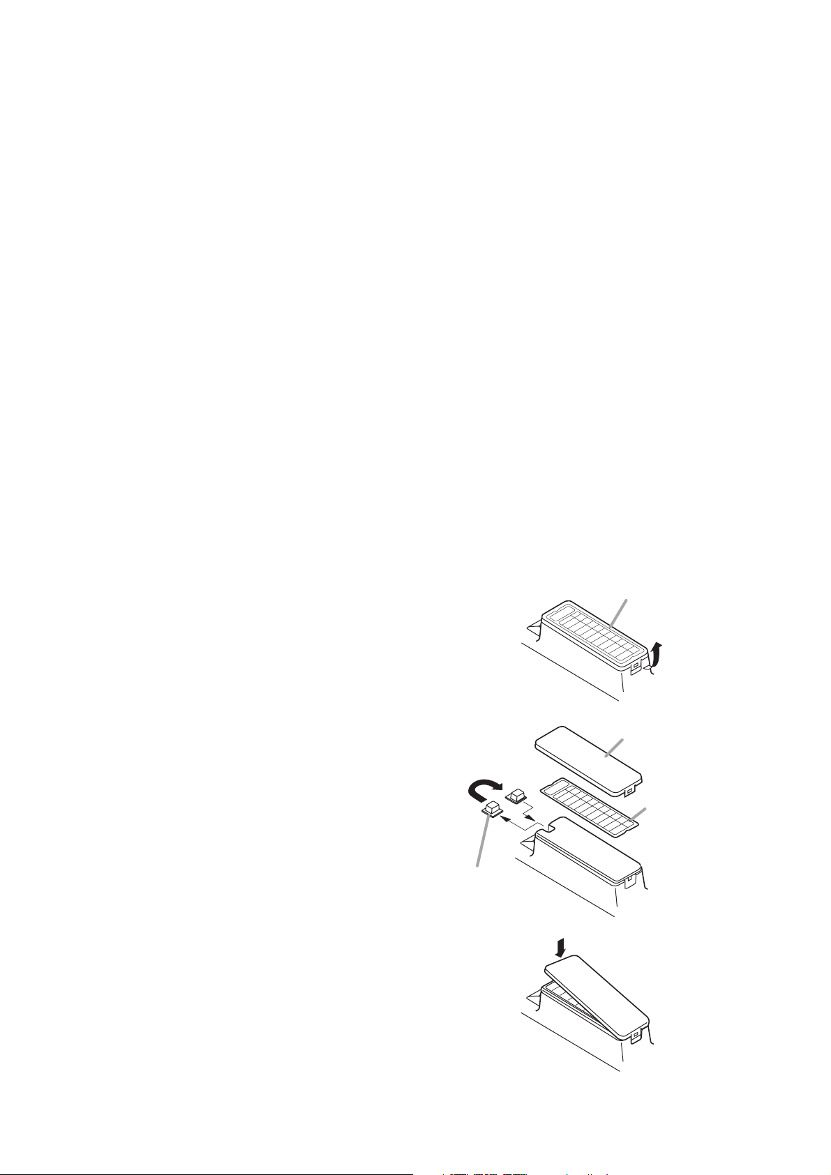
5. WHEN MOUNTING THE STATION ON A WALL
When mounting the station on a wall, the orientation of the handset hook needs to be changed.
Step 1. Raise the number directory cover forward tab.
Step 2. Remove both the number directory cover and the
directory. Remove the handset hook and reverse
its orientation, then replace.
Step 3. After replacing the directory on the station, hook
the directory cover's forward tab and push on the
upper part of the directory cover.
Reverse the orientation.
Handset hook
Number directory cover
Number directory cover
Number directory
Page 3

6. WALL MOUNTING
The optional YC-280 Wall mounting bracket is required.
The YC-280 can be mounted to a one-gang electrical box.
6.1. Mounting
Step 1. Install the YC-280 to the wall.
Notes
• Use the appropriate screws for the construction
of wall.
• Wood screws 3.5 x 20 are supplied with the
YC-280.
• No fitting screws for an electrical box are
supplied.
Use commercially available screws.
Step 2. Hang the station on the wall mounting bracket
hook to install.
Push down the station body in the arrow
direction shown at right.
Unit: mm
6.3. YC-280 Dimensional Drawing
Unit: mm
6.2. Installation Completion Drawing
7. DESKTOP INSTALLATION
The station can be used on a desk. In desktop installations, the front operation panel can be inclined 16˚ from the desk
surface for easier operation by attaching the YC-280 Wall mounting bracket to its bottom surface.
7.1. Attaching the Bracket
Step 1. Attach the four rubber feet to the YC-280's bottom surface.
Step 2. Hang the YC-280's hook on the station's wall bracket
mounting slot to install.
Push up the YC-280 in the arrow direction shown below.
7.2. Installation Completion Drawing
Unit: mm
148
208
YC-280
N-8510MS
Rubber foot mounting position
(desktop application)
2-ø4.5
5037
YC-280 Wall mounting
bracket (optional)
Wall
surface
2
1
Hook
Wood screw 3.5 x 20
(supplied with the YC-280)
4.6 x 6
60
140
83.523.5
60
80
100
YC-280
66.2
72.1
83.5
4.5 x 10
N-8510MS
YC-280 Wall mounting bracket
205.2
16º
101.8
YC-280
Hook
Rubber foot
(supplied with the YC-280)
Page 4

8. WIRING
9. ACCESSORIES
CD*2.................................................. 1
Ferrite clamp ..................................... 1
*
2
Contains the N-8000 setting software program and the
N-8000 series instruction manual.
The Setup Launcher is automatically started when the
supplied CD-ROM is inserted into the PC's drive.
Note
If your PC's CD drive is not compatible with the
AutoRun function, the setup guide is not automatically
started even when the CD is inserted.
Use either "Explorer" or "My Computer" to execute the
following files, or use [Start Run] in the Task Bar and
enter the following command.
<Drive where CD is placed> \index.html
For example, when the CD is placed in the "d" drive,
d:\index.html
10. OPTIONAL PRODUCTS
AC adapter: AD-1210P*
3
Wall mounting bracket: YC-280
*
3
Consult your TOA dealer when using an equivalent
adapter.
133-06-295-10
URL: http://www.toa.jp/
Traceability Information for Europe
(EMC directive 2004/108/EC)
Manufacturer:
TOA Corporation
7-2-1, Minatojima Nakamachi, Chuo-ku, Kobe, Hyogo, Japan
Authorized representative:
TOA Electronics Europe GmbH
Suederstrasse 282, 20537 Hamburg, Germany
[Power supply connection]
The following 2 methods are available for
supplying power to the station.
• From a DC 12 V AC adapter
• From an IEEE802.3af compliant PoE
switching hub
(For connection, refer to the instruction
manual supplied with the switching hub.)
N-8510MS rear
DC INPUT
CONTACT IN
CH
12V 400mA
LAN
[AC adapter connection]
Cable
Connect the AC adapter*1.
Install the supplied ferrite
clamp on the AC adapter
cable by winding the
cable around the ferrite
clamp once.
Ferrite clamp (accessory)
*1 Use the AC adapter AD-1210P (optional) or its equivalent.
As for the usable adapter, consult your TOA dealer.
[Control line connection]
Connect the external control equipment such
as a switch or sensor to this terminal.
Press down the desired push-in
terminal button with a tip of standard
driver, and insert the cable securely.
11 mm
• Applicable cables are as follows.
Conductor diameter:
ø0.4 – 1.3 mm (AWG16 – 26), Solid wire
ø0.7 – 1.4 mm (AWG16 – 22), Stranded wire
COM HOT
To network
[Network connection]
Can be connected to a network of
10BASE-T/100BASE-TX in auto-sensing.
Use a UTP category 5 straight-through
cable with an RJ-45 connector for this
connection.
Note
When using a PoE hub, be sure to
connect equipment having a protective
earth terminal (or power cable with earth)
and ground the earth terminal. Failure to
do so may cause equipment malfunction.
 Loading...