

Page 1
Service Manual
Model #: VIZIO GV46L HDTV
VIZIO GV46L HDTV10A
(For Samsung Panel)
V, Inc
320A Kalmus Drive Costa Mesa, CA 92626
TEL : +714-668-0588 FAX :+714-668-9099
Top Confidential
Page 2

Table of Contents
CONTENTS PAGE
Sections
1. Features 1-1
2. Specifications 2-1
3. On Screen Display
3-1
4. Factory Preset Timings 4-1
5. Pin Assignment 5-1
6. Main Board I/O Connections
6-1
7. Theory of Circuit Operation 7-1
8. Waveforms 8-1
9. Trouble Shooting
9-1
10. Block Diagram 10-1
11. Spare parts list 11-1
12-1. Complete Parts List (GV46L HDTV_Samsung) 12-1
12-2. Complete Parts List (GV46L HDTV10A_Samsung)
12-2
Appendix
1. Main Board Circuit Diagram
2. Main Board PCB Layout
3. Assembly Explosion Drawing
Block Diagram
VIZIO GV46L_HDTV,GV46L_HDTV10A Service Manual
Page 3

VINC Service Manual
VIZIO GV46L_HDTV,GV46L_HDTV10A
COPYRIGHT © 2000 V, INC. ALL RIGHTS RESERVED.
IBM and IBM products are registered trademarks of International Business Machines
Corporation.
Macintosh and Power Macintosh are registered trademarks of Apple Computer, Inc.
VINC and VINC products are registered trademarks of V, Inc.
VESA, EDID, DPMS and DDC are registered trademarks of Video Electronics Standards
Association (VESA).
Energy Star is a registered trademark of the US Environmental Protection Agency (EPA).
No part of this document may be copied, reproduced or transmitted by any means for any
purpose without prior written permission from VINC.
FCC INFORMATION
This equipment has been tested and found to comply with the limits of a Class B digital device,
pursuant to part 15 of the FCC Rules. These limits are designed to provide reasonable
protection against harmful interference in a residential installation. This equipment generates,
uses and can radiate radio frequency energy, and if not installed and used in accordance with
the instructions, may cause harmful interference to radio communications. However, there is
no guarantee that the interference will not occur in a particular installation. If this equipment
does cause unacceptable interference to radio or television reception, which can be
determined by turning the equipment off and on, the user is encouraged to try to correct the
interference by one or more of the following measures -- reorient or relocate the receiving
antenna; increase the separation between equipment and receiver; or connect the into an
outlet on a circuit different from that to which the receiver is connected.
FCC WARNING
To assure continued FCC compliance, the user must use a grounded power supply cord and
the provided shielded video interface cable with bonded ferrite cores. Also, any unauthorized
changes or modifications to Amtrak products will void the user’s authority to operate this
device. Thus VINC Will not be held responsible for the product and its safety.
CE CERTIFICATION
This device complies with the requirements of the EEC directive 89/336/EEC with regard to
“Electromagnetic compatibility.”
SAFETY CAUTION
Use a power cable that is properly grounded. Always use the AC cords as follows – USA (UL);
Canada (CSA); Germany (VDE); Switzerland (SEV); Britain (BASEC/BS); Japan (Electric
Appliance Control Act); or an AC cord that meets the local safety standards.
VIZIO GV46L_HDTV,GV46L_HDTV10A Service Manual
Page 4

Chapter 1 Features
y High resolution 1366 x 768 with wide screen
y Built-in digital HDTV and standard TV combination TV tuner
y All TV formats supported (1080i, 720p, 480 p and 480i)
y Computer Monitor (RGB): up to1366 x 768 (H x V)
y Wall mounting capable with and without speakers
y 2.1 virtual surround sound (TruSurround XT) with 20W subwoofer
y Dual HDMI (High Definition Multimedia Interface)
y Independent Red, Green and Blue adjustment in TV, Video, HDMI and VGA for
user fine tuning of color temperature with reset.
y Zero Bright Pixel
y PIP, POP, CC, V-Chip, 3D Comb Filter, Zoom, Freeze, DCDi De-Interlace, 3:2 or
2:2 Reverse Pull-down, ATSC, with 8VSB & QAM demodulation, with MPEG-2
decoding, NTSC Video decoding via RF (Antenna, Cable or Satellite) or Video
(CVBS, S-Video or Component), Progressive Scan Video via Component YPbPr,
VGA or HDMI, HDTV via HDMI or Component YPbPr,
CONFIDENTIAL – DO NOT COPY
Page 1-1
File No. SG-0199
Page 5

Chapter 2 Specification
1. General specification
Native Resolution
Effective Display Size
Aspect Ratio
Display Color
Brightness
Contrast Ratio
TV system
PC Inputs
Video Inputs
1366 (H)X768 (V) pixels,
1018.353 (H) x 572.544 (V) mm
16:9
8 bit, 16.7M
400 cd/ m
1,200:1 (Typical, panel spec).
NTSC/ATSC/ QAM
15pins D-sub, HDMI-DVI
2 x S-Video
2 x AV inputs (CVBS; RCA type)
2 x Component (Y Pb/Pr Cb/Cr)
2 x HDMI
2
(Min)
Audio Inputs
Audio Outputs
Audio
Power Input
Power Consumption
CONFIDENTIAL – DO NOT COPY
6 x Stereo RCA (R/L), 1 x PC Mini-Jack
Analog - 1 x stereo RCA (R/L)
1 x headphone
Digital – 1 x SPDIF Optical
10W8ȍ X 2 + 20W8ȍ X 1
100 to 240 Vac
320W Max
Page 2-1
File No. SG-0199
Page 6
2. Optical characteristics
Item Specification Note
Display Pixels 1366 (H) x 768 (V) pixels
Pixel Pitch 0.7455 (H) x0.2485 (V) mm*3
Pixel Arrangement RGB vertical stripe
Color Depth 8 bit, 16.7M colors
Active Display Area 921.6 (H) x 519.2 (V) ±0.5 mm
Surface treatment of
Hard coating
Brightness 400 cd/m2 (min)
Contrast ratio (panel
spec)
Color coordinates
Viewing angle
3H
1,200:1 (Typical, dark room)
Cool (9300K):: x=0.283 ± 0.03,y=0.297 ± 0.03 RGB
Standard (6500K): x=0.313 ± 0.03, y=0.329 ± 0.03
Warm (5400K): x=0.332 ± 0.03,y=0.348 ± 0.03 RGB
User: x= 0.280± 0.03, y= 0.290± 0.03 RGB
øL 75
Hor.
øR 75
øU 75
Ver.
øD 75
RGB
/VIDEO
3. Power Supply
a. Input voltage 100-240Vac, 50/60Hz
b. Input current 3.2A or less (at AC 100V/60Hz)
c. Inrush current 60A at Vac=120V
d. Power consumption 320 W Max
e. Standby/Power-off 3 watts max. (at 120 Vac)
CONFIDENTIAL – DO NOT COPY
Page 2-2
File No. SG-0199
Page 7
4. Environment
4.1 Operating
a. Temperature 0~35к
b. Humidity 0%~90% RH (No condensation)
4.2 Non-operating
a. Temperature -20~60к
b. Humidity 0%~90% RH (No condensation)
4.3 Altitude
a. Operating 0~14,000 ft
b. Non-operating 0~40,000 ft
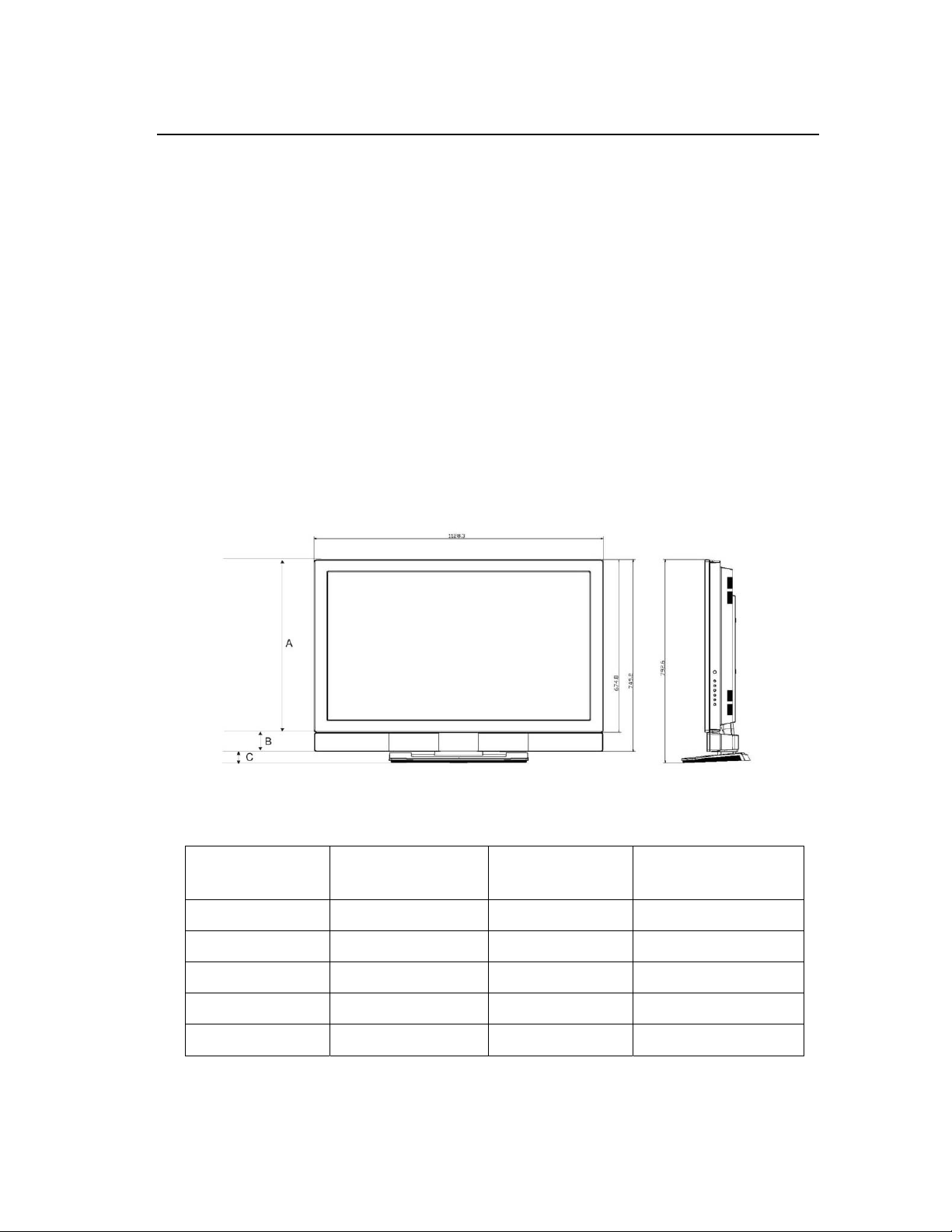
5. Dimensions & Weight
A: Display Module B: Speaker C: Base
Display Module
Display Module +
Speaker
a. Height 674.8 mm 749.2 mm 792.6 mm
b. Width 1128.3 mm 1128.3 mm 1128.3 mm
c. Depth 120.9 mm 132.9 mm 269.3 mm
d. Net weight 30.8+/- 0.5 kgs 33.50+/- 0.5 kgs 37.00 +/- 0.5 kgs
e. Gross Weight -- -- 44 +/- 1 kgs
CONFIDENTIAL – DO NOT COPY
Display Module +
speaker + Base
Page 2-3
File No. SG-0199
Page 8

6. Packaging Specification
6.1 Packaged dimensions
a. Height 960+/- 20 mm
b. Width 1300+/- 20mm
c. Depth 374 +/- 20 mm
6.2 Pallet Load
a. Sea 3 units/pallet
6.3 Container Load
a. 40’ container 108 units (@3 x 36 pallets= 108 units)
b. 20’ container 48 units (@3 x 16 pallets= 48 units)
CONFIDENTIAL – DO NOT COPY
Page 2-4
File No. SG-0199
Page 9

Chapter 3 On Screen Display
ʳ
ʳ
ʳ
1. Analog Menu - RGB/AV/Component/HDMI/TV
Image Settings
ModeʳLevel 1
VIDEO Picture Mode
VIDEO Brightness(0~100) ʳʳ
VIDEO Contrast(O~100) ʳʳʳ
VIDEO
VIDEO Hue(-50~50) ʳʳʳ
VIDEO Sharpness(0~24) ʳʳʳ
VIDEO Advanced ʳʳʳ
VIDEO ʳ Noise Reduction ʳʳ
VIDEO ʳʳ Motion(0~16) ʳ
VIDEO ʳʳ Digital(0~64) ʳ
VIDEO ʳ Fleshtone
VIDEO ʳ
VIDEO
VIDEO Custom Color* ʳʳʳ
Saturation(0Д100)
Level 2
Vivid, Movie, Game,
Sport, Custom
ʳʳʳ
Dynamic Contrast
(0,1,2,3)
Backlight (High,
Medium, Low)
Level 3
ʳʳ
Off, High, Medium,
Low
ʳʳ
Level 4
ʳ
VIDEO ʳ Red(0~100) ʳʳ
VIDEO ʳ
VIDEO ʳ Blue(0~100) ʳʳ
PC ʳ Auto Adjustment ʳʳ
PC ʳ lmage Position ʳʳ
PC ʳ Phase ʳʳ
PC ʳ CIocks/Line ʳʳ
PC ʳ Color Temp ʳʳ
PC ʳʳ Warm(5400K) ʳ
PC ʳʳ Standard(6500K) ʳ
PC ʳʳ Cool(9300K) ʳ
PC ʳʳ User ʳ
PC ʳʳʳ Red(0~100)
PC ʳʳʳ
PC ʳʳʳ Blue(0~100)
PC
Green(0Д100)
Backlight (High,
Medium, Low)
ʳʳ
Green(0Д100)
CONFIDENTIAL – DO NOT COPY
Page 3-1
File No. SG-0199
Page 10
When “Custom” in “Picture Mode” is selected.
Display Settings
Mode Level 1 Level 2 Level 3 Level 4
VIDEO Aspect Ratio
PC Aspect Ratio
PIP
PIP Mode Off, Large PIP, Small
* RGB doesn’t support Zoom function
** Only AV and Component 480i/480p support Panoramic function.
*** Please see 4.3 “PIP/POP Table” for PIP/POP matrix for all inputs.
16:9Ε4:3ΕZoom*Ε
Panoramic**
16:9Ε4:3
PIP, POP
PIP Position Top-Left, Top-Right,
Bottom-Left,
Bottom-Right
PIP Input ***
Audio Settings
Mode Level 1 Level 2 Level 3 Level 4
ʳ Bass(0~20) ʳ
ʳ Treble(0~20) ʳ
ʳ Balance(-10~10) ʳ
ʳ SRS TS XT* (On, Off) ʳ
ʳ Auto Volume(On, Off) ʳ
ʳ Speakers(On, Off) ʳ
ʳ Audio Out** Fixed Volume,
Variable Volume
* SRS TS XT doesn’t support DTV/TV and line out.
** When “Speakers” is off
CONFIDENTIAL – DO NOT COPY
ʳ
ʳ
ʳ
ʳ
ʳ
ʳ
ʳ
Page 3-2
File No. SG-0199
Page 11
Parental Controls
Mode Level 1 Level 2 Level 3 Level 4
VIDEO Password ʳʳʳ
VIDEO ʳ Settings ʳʳ
VIDEO ʳʳ TV Rating ʳ
VIDEO ʳʳʳ
VIDEO ʳʳʳ
VIDEO ʳʳʳ
VIDEO ʳʳʳ
VIDEO ʳʳʳ
VIDEO ʳʳʳ
VIDEO ʳʳʳ Unblocked
VIDEO ʳʳ Movie Rating ʳ
VIDEO ʳʳʳ
VIDEO ʳʳʳ
VIDEO ʳʳʳ
VIDEO ʳʳʳ
VIDEO ʳʳʳ
VIDEO ʳʳʳ
VIDEO ʳʳʳ Unblocked
TV Youth (UnblockedΕBlocked)
TV Youth 7 (UnblockedΕBlocked)
TV G (UnblockedΕBlocked)
TV PG (UnblockedΕBlocked)
TV 14 (UnblockedΕBlocked)
TV MA (UnblockedΕBlocked)
Movie G (UnblockedΕBlocked)
Movie PG(UnblockedΕBlocked)
Movie PG-13(UnblockedΕBlocked)
Movie R(UnblockedΕBlocked)
Movie NC-17(UnblockedΕBlocked)
Movie X(UnblockedΕBlocked)
VIDEO ʳʳ Block Unrated
(No, Yes)
VIDEO ʳ Change
Password
VIDEO ʳʳ Please enter
VIDEO ʳʳ Please re-enter
VIDEO ʳ Clear All
(No,Yes)
CONFIDENTIAL – DO NOT COPY
ʳʳ
new password
new password
ʳʳ
ʳ
ʳ
ʳ
Page 3-3
File No. SG-0199
Page 12

Setup
Mode Level 1 Level 2 Level 3 Level 4
ʳ Closed Caption ʳʳ ʳ
Display CC1, CC2, CC3, CC4, TEXT1,
TEXT2, TEXT3, TEXT4
Captions on mute On, Off
ʳ
ʳ
ʳ
TV
TV
TV
TV
DTV
* DTV menu is followed by options in the following point 2 when it is selected.
2. DTV Menu
Language English, French,
Spanish
Factory Reset (No,Yes) ʳʳ
Image Cleaner ʳʳ
TV Menu ʳʳ
ʳ Auto Scan ʳ
ʳ Set Channel Add/Skip
ʳ Cable/Antenna ʳ
DTV Menu* ʳʳ
Firmware Version
ʳ
ʳ
ʳ
ʳ
ʳ
ʳ
ʳ
ʳ
ʳ
Level 1 Level 2 Level 3 Level 4 Level 5
DTV Tuner Setup ʳʳʳʳ
ʳ Time Zone ʳʳʳ
ʳʳ Hawaii ʳʳ
ʳʳ Eastern Time ʳʳ
ʳʳ Indiana ʳʳ
ʳʳ Central Time ʳʳ
ʳʳ Mountain Time ʳʳ
ʳʳ Arizona ʳʳ
ʳʳ Pacific Time ʳʳ
ʳʳ Alaska ʳʳ
ʳ Cable/Air/Auto ʳʳʳ
CONFIDENTIAL – DO NOT COPY
File No. SG-0199
Page 3-4
Page 13

Level 1 Level 2 Level 3 Level 4 Level 5
ʳ Scan* ʳʳʳ
ʳ Manual Scan* ʳʳ
ʳʳ Scan mode ʳʳ
ʳʳ ʳ Add-on Mode ʳ
ʳʳ ʳ Range Mode ʳ
ʳʳ ʳ ʳ From Channel
ʳʳ ʳ ʳ To Channel
ʳ Channel Skip ʳʳʳ
ʳ Digital Audio Out ʳʳʳ
ʳʳ PCM ʳʳ
ʳʳ OFF ʳʳ
ʳʳ Dolby Digital ʳʳ
Closed Caption ʳʳʳʳ
ʳ Analog Closed
CC1~CC4ޔOFF
ʳʳ
Caption
ʳ Digital Closed
CAPTION
Service 1~Service 6,
OFF
ʳʳ
ʳ Digital Closed Style ʳʳʳ
ʳʳ As Broadcaster ʳʳ
ʳʳ Custom ʳʳ
ʳʳ ʳ Font Size ʳ
ʳʳ ʳ ʳ Large
ʳʳ ʳ ʳ Small
ʳʳ ʳ ʳ Medium
ʳʳ ʳ Font Color ʳ
ʳʳ ʳ ʳ Black
ʳʳ ʳ ʳ White
ʳʳ ʳ ʳ Green
ʳʳ ʳ ʳ Blue
ʳʳ ʳ ʳ Red
ʳʳ ʳ ʳ Cyan
ʳʳ ʳ ʳ Yellow
ʳʳ ʳ ʳ Magenta
ʳʳ ʳ Font Opacity ʳ
ʳʳ ʳ ʳ Solid
ʳʳ ʳ ʳ Translucent
ʳʳ ʳ ʳ Transparent
CONFIDENTIAL – DO NOT COPY
Page 3-5
File No. SG-0199
Page 14

Level 1 Level 2 Level 3 Level 4 Level 5
ʳʳ ʳ Background Color ʳ
ʳʳ ʳ ʳ Black
ʳʳ ʳ ʳ White
ʳʳ ʳ ʳ Green
ʳʳ ʳ ʳ Blue
ʳʳ ʳ ʳ Red
ʳʳ ʳ ʳ Cyan
ʳʳ ʳ ʳ Yellow
ʳʳ ʳ ʳ Magenta
ʳʳ ʳ Background Opacity ʳ
ʳʳ ʳ ʳ Solid
ʳʳ ʳ ʳ Translucent
ʳʳ ʳ ʳ Transparent
ʳʳ ʳ Window Color ʳ
ʳʳ ʳ ʳ Black
ʳʳ ʳ ʳ White
ʳʳ ʳ ʳ Green
ʳʳ ʳ ʳ Blue
ʳʳ ʳ ʳ Red
ʳʳ ʳ ʳ Cyan
ʳʳ ʳ ʳ Yellow
ʳʳ ʳ ʳ Magenta
ʳʳ ʳ Window Opacity ʳ
ʳʳ ʳ ʳ Solid
ʳʳ ʳ ʳ Translucent
ʳʳ ʳ ʳ Transparent
Parental control
CONFIDENTIAL – DO NOT COPY
Page 3-6
File No. SG-0199
Page 15

Chapter 10 Trouble Shooting
A. SYSTEM OVERVIEW
Iverter board
Display board
AUDIO board
Main board
Iverter board
Power supply board
IR board
ATSC Board
CONFIDENTIAL – DO NOT COPY
Page10-1
File No. SG-0199
Page 16

B. PCB PARTS NAME/NUMBER AND FUNCTION DESCRIPTION
PART NAME PART NUMBER FUNCTION DESCRIPTION
POWER SUPPLY BOARD PROVIDE ALL THE POWER FOR TV SET
MAIN BOARD 364600120150 CONNECTING TO TRANSFER DISPLY SIGNAL
TO PDP SET, AMPLIFIER THE AUDIO SIGNAL TO
THE SPEAKER
IR BOARD 364600120189 RECEIVE THE REMOTE CONTROLER AND DISPLAY
SYSTEM STATUS LED
DISPLAY BOARD 364600120156 KEYPAD FUNCTION FOR MANUAL OPERATE TV
ATSC BOARD 364600120190 DTV/TV MODLE
AUDIO BOARD 364600120137
C. BOARD PICTURE
MAIN BOARD
CONFIDENTIAL – DO NOT COPY
Page10-2
File No. SG-0199
Page 17

DISPLAY BOARD
IR BOARD
CONFIDENTIAL – DO NOT COPY
Page10-3
File No. SG-0199
Page 18

ATSC BOARD
AUDIO BOARD
CONFIDENTIAL – DO NOT COPY
Page10-4
File No. SG-0199
Page 19

PDP DISPLAY NOTHING
1. Main board & ATSC board block diagram
ARXD
ATXD
ATXD_HUD
ARXD_HUD
U20 4052
I/O SW
ADATA[0:23]
IPCLK0/AHS/AVS/AHREF_DE
HDMI1 AUDIO
BDATA[0:23]
IPCLK1/BHS/BVS/BDE
HDMI2 AUDIO
A4/B4/C4
A3/B3/C3_CTZ
A3/B3/C3_HUD
U43 CS3443
HDMI1 LR DAC
U36 CS3443
HDMI2 LR DAC
U46 IDTQS3253
HDMI2 AUDIO SW
U42 IDTQS3253
HDMI1 AUDIO SW
51_RXD/51_TXD
U10
MT5351
HDMI1_AUDIO_L/R
HDMI2_AUDIO_L/R
AudioAV1_R/L
AudioAV1_R/L
COMP1_Audio_R/L
COMP2_Audio_R/L
VGA_AUDIO_L/R
ATSC Audio L/R
W14
W5
AUDIO L/R
OUT
W12
Headphone
W8
CN17
W13
CN16
W7
W11
W10
W13
U37 24LC02
EEPROM HDMI1
U40 24LC02
EEPROM HDMI2
W6
Y Pr Pb
Y Pr Pb
COMP1_Audio_R/L
COMP2_Audio_R/L
AudioAV1_R/L
CVBS1
CVBS2
AudioAV2_R/L
Y1/C1
Y2/C2
VGA_AUDIO_L/R
TUNER
FQD1236/F H-5
TV
TUNER SIF
NTSC CVBS
ATSC Y
Pr Pb
A2/B2/C2
U60 TS5V330
SW
ANLOG DDC
VS / HS
R G B
UC_SCL/UC_SDA
VGA_SCL / VGA_SDA
DTV
U40 24LC128
EEPROM(8051)
U38
SST89C58
U42 Sil 9011
HDMI RS
U35 Sil 9011
HDMI RS
U21 24LC02
EEPROM VGA
U45 74HCT14
Inverting Schmitt Trgger
U22 M61323FP
VEDIO SW
U23 M61323FP
VEDIO SW
U24 M61323FP
VEDIO SW
U9
MT5112
U48 TS5V330
AUDIO SW
4/2 I/O
U49 TS5V330
AUDIO SW
4/2 I/O
ATSC Audio L/R
ATSC Y Pr Pb
FL8532_CTZ
51_RXD/51_TXD
IPCLK0/AHS/AVS/AHREF_DE
IPCLK1/BHS/BVS/BDE
MSTR2_SCL/MSTR2_SDA
MSTR1_SCL/MSTR1_SDA
VGA_SCL / VGA_SDA
ADATA[0:23]
BDATA[0:23]
AIR_RAW_HS_CS/AIR_RAW_VS
SV4_CTZ
SV2_CTZ
SV3_CTZ/A1_CTZ
B1_CTZ/C1_CTZ
A4/B4/C4_CTZ
A3/B3/C3_CTZ
A2/B2/C2_CTZ
JTAG_BS_TCK/TDO/TMS/TDI/TRST
NTSC CVBS(SV1_HUT)
MSTR1_SCL/MSTR1_SDA
JTAG_BS_TCK/TDO/TMS/TDI/TRST
ATXD_HUD
ARXD_HUD
AIR_RAW_HS_CS/AIR_RAW_VS
A4/B4/C4_HUD
A3/B3/C3_HUD
A2/B2/C2_HUD
SV4_HUD
SV2_HUD
SV3_HUD/A1_HUD
B1_HUD/C1_HUD
IPCLK1/BHS/BVS/BDE
BDATA[0:23]
NTSC CVBS(SV1_CTZ)
MSTR2_SCL/MSTR2_SDA
CH4_R/L
CH3_R/L
CH2_R/L
CH1_R/L
TUNER SIF
HY5DU56822CT-D4
U17 DDR RAM CTZ
ARXD
ATXD
U32 P4450G
AUDIO
PROCESS
Frame Store
DDR Interface
UART
GPIO
2 Wire
Controller
2 Wire
Controller
Digital A
Input
Digital B
Input
Analog
input
JTAG Boundary
Scan
2 Wire
Controller
JTAG Boundary
Scan
UART
Analog
input
GPIO
LVDS
Display
Interface
FL8125_HUD
VEDIO
HY5DU56822CT-D4
U16 DDR RAM HUD
Frame Store
DDR Interface
2 Wire
Controller
LVDS
Display
Interface
OCM External
SRAM
I2CCM
Serial ROM
Interface
AUDIO
SUBWoofer
Lineout_R/L
HLIN/HRIN
RCA Lineout_R/L
SCL-33V / SDA-33V
MSTR0_SCL/MSTR0_SDA
TV/DTV
W1
XU1 A29LV320D
MEMERY_CTZ
NC7SB3157
U18 BUS SW
U11 24LC32
EEPROM HUD
U12 SST25VF040
FLASH 512K HUD
U33 PT2308
AUDIO DRIVER
U33 PT2308
AUDIO DRIVER
U34 PT2308
AUDIO DRIVER
LED BLACKLIGHT
J12
CN5
KEY PAD + IR
U25 F75373S
CN12
CN13
J11
Audio connect
Display
MP7772
AUDIO_AMP
MP7782
AUDIO_AMP
J3
Audio out
J4
Audio out
CONFIDENTIAL – DO NOT COPY
Page10-5
File No. SG-0199
Page 20

LCD
PDP DISPLAY NOTHING(Analog HD1/AC on/off default)
Start
Powe r LED is lighti ng?
Yes
Powe r LED is lighti ng?
Yes
Powe r LED is lighti ng?
Yes
PDP DISPLAY NOTHING(Analog HD1 without Y signal)
LCD
No
Check AC power cord
No
Press Meun or Info.
Is there any OSD’s logo
Check internal cable?
1.LVDS cable.
No
Check internal cable?
1.CN1’s cable
2.CN3’s cable
D10,D11 LED is lighting?
Yes
Check input source
No
No
Check W1 pin 27 is high?
(Display_ON)
No
Check main board CN3 pin 4Î studyby +5V
Check CN3 pin 3Î RLY_ON(high)
Check CN3 pin 2Î VS_ON(high)
No
Check Fuse open?
(F2,F3,F4)
No
Yes
Yes
Yes
No
U13 fail
Yes
No
Check U13 pin A D14.
Remove R87.
Is AD14 high?
Check U3.4Î3.3V
Check U8Î1.8V
Check U9Î2.5V
If power_off Îhigh
U2,U5Î ON
Check +3.3V_SW
,+5V_SW,+12V_SW
(pin 5,6 and pin 7,8)
No
Yse
Check CN1Îpin 1,2,3 = +5V
Yes
Panel powe r
No
No
No
No
U13 fail
pin 7,8 = +12V
No
fail
Fuse fail
U3 fail
U8 fail
U9 fail
U2,U5 fail
Block 1
No
Is picture on screen?
Check component 1
(Y signal) ÎC252
Is there sync?
Use GProbe connect
Does scaler detect the signal?
CONFIDENTIAL – DO NOT COPY
Yes
from main to PC.
No
Trace componect 1 from
No
Input To U13 circuit
Check R190,R191
U13 fail
1
Page10-6
File No. SG-0199
Page 21

PDP DISPLAY NOTHING(Analog HD1 without Pb signal)
LCD
BLOCK 1
No
Check component 1
Is picture on screen?
LCD
PDP DISPLAY NOTHING(Analog HD1 without Pr signal)
BLOCK 1
Is picture on screen?
PDP DISPLAY NOTHING(Analog HD1 on PIP mode without Y signal)
LCD
BLOCK 1
(Pb signal) ÎC259
Is there sync?
Use GProbe connect
from main to PC.
Does scaler detect the signal?
No
Check component 1
(Pr signal) Î C264
Is there sync?
Use GProbe connect
from main to PC.
Does scaler detect the signal?
No
Trace componect 1 from
Input To U13 circuit
Check R196,R198
Yes
No
U13 fail
No
Trace componect 1 from
Input To U13 circuit
Check R204,R201
Yes
No
U13 fail
Is picture on screen?
No
Does scaler detect the signal?
CONFIDENTIAL – DO NOT COPY
Check component 1
(Y signal) =>C255
Is there sync?
Yes
Use GProbe connect
from main to PC.
No
Trace componect 1 from
No
Input To U10 circuit
Check R193,R191
U10 fail
2
Page10-7
File No. SG-0199
Page 22

PDP DISPLAY NOTHING(Analog HD1 on PIP mode without Pb signal)
LCD
BLOCK 1
No
Is picture on screen?
PDP DISPLAY NOTHING(Analog HD1 on PIP mode without Pr signal)
LCD
BLOCK 1
Is picture on screen?
LCD
PDP DISPLAY NOTHING(Analog HD2 without Y signal)
BLOCK 1
Check component 1
(Pb signal) ÎC255
Is there sync?
Use GProbe connect
from main to PC.
Does scaler detect the signal?
No
Check component 1
(Pr signal ) ÎC255
Is there sync?
Use GProbe connect
from main to PC.
Does scaler detect the signal?
No
Trace componect 1 from
Input To U10 circuit
Check R200,R198
Yes
No
U10 fail
No
Trace componect 1 from
Input To U10 circuit
Check R205,R204
Yes
No
U10 fail
Is picture on screen?
No
(Y signal) ÎC258,R195
Use GProbe connect
Does scaler detect the signal?
CONFIDENTIAL – DO NOT COPY
Check component 2
Is there sync?
Yes
from main to PC.
Check U23
No
No
outnputÎpin 31
InputÎ pin 13
Input clamp voltageÎpin 3(+5V)
Output clamp voltageÎpin 32(+5V)
VCC3Îpin 22,23(+5V)
Input_switch_selectÎhigh(+5V)
U13 fail
Yes
No
U23 fail
Check before U23’s circuit
1.C263,C265(AC coupled)
2.R209
3.R216(75ohm)
No
Input source fail
3
Page10-8
File No. SG-0199
Page 23

PDP DISPLAY NOTHING(Analog HD2 without Pb signal)
LCD
BLOCK 1
Check U23
Is no blue color on screen?
No
Check componen t 2
(Pb si gnal) ÎC260,R197
Is there sync?
No
Yes
outnputÎpin 28
Inpu tÎ pin 15
Input clamp voltageÎpin 5(+5V)
Output clamp voltageÎpin 29(+5V )
VCC3Îpin 22,23(+5V)
Input_switch_selectÎhigh(+5V)
No
U23 fail
Use GProbe connect
from main to PC.
Does scaler detect the signal?
LCD
PDP DISPLAY NOTHING(Analog HD2 without Pr signal)
BLOCK 1
No
Check componen t 2
Is no red c olor on screen ?
LCD
PDP DISPLAY NOTHING(Analog HD2 on PIP mode without Y signal)
BLOCK 1
Is picture on screen?
(Pr signal) ÎC254,R192
Is there signal?
Use GProbe connect
from main to PC.
Does scaler detect the signal?
No
Check component 2
(Y signal) ÎC287,R212
Is there sync?
Yes
No
U13 fail
No
Input clamp voltageÎpin 1(+5V)
Output clamp voltageÎpin 35(+5V)
Yes
No
Input_switch_selectÎhigh(+5V)
U13 fail
No
Input clamp voltageÎpin 3(+5V)
Output clamp voltageÎpin 32(+ 5V)
Input_switch_selectÎhigh(+5V)
Yes
Check U23
outnputÎpin 34
Inpu tÎ pin 11
VCC3Îpin 22,23(+5V)
Yes
Check U24
outnputÎpin 31
Inpu tÎ pin 13
VCC3Îpin 22,23(+5V)
Check before U23’s circ uit
1.C268,C269(AC coupled)
2.R211
3.R217(75ohm)
No
U23 fail
Check before U23’s circ uit
1.C256,C261(AC coupled)
2.R215
3.R218(75ohm)
No
U24 fail
No
No
Input source fail
Input source fail
Use GProbe connect
Does scaler detect the signal?
CONFIDENTIAL – DO NOT COPY
from main to PC.
No
U10 fail
Yes
Check before U24’s circuit
1.C282,C285(AC coupled)
2.R209
3.R216(75ohm)
No
Input source fail
4
Page10-9
File No. SG-0199
Page 24

LCD
PDP DISPLAY NOTHING(Analog HD2 on PIP mode without Pb signal)
BLOCK 1
Check U24
Is no blue color on screen?
No
Check component 2
(Pb si gnal) ÎC288,R213
Is there sync?
No
Yes
outnputÎpin 28
Input Î pin 15
Input clamp voltageÎpin 5(+5V)
Output clamp voltageÎpin 29(+5V)
VCC3Îpin 22,23(+5V)
Input_switch_selectÎhigh(+5V)
No
U24 fail
Use GProbe connect
from main to PC.
Does scaler detect the signal?
LCD
PDP DISPLAY NOTHING(Analog HD2 on PIP mode without Pr signal)
BLOCK 1
No
Is no red color on screen?
LCD
PDP DISPLAY NOTHING(RGB)
BLOCK 1
Is picture on screen?
Check component 2
(Pr sign al) ÎC284,R210
Is there signal?
Use GProbe connect
from main to PC.
Does scaler detect the signal?
H sync output Î U45 pin4,R181
No
V sync output Î U45 pin8,R184
Is there signal?
Yes
Check U45
No
U10 fail
No
Input clamp voltageÎpin 1(+5V)
Output clamp voltageÎpin 35(+5V)
Yes
No
Input_switch_selectÎhigh(+5V)
U10 fail
No
Yes
Check before U24’s circuit
1.C289,C290(AC coupled)
2.R211
3.R217(75ohm)
Check U24
outnputÎpin 34
Input Î pin 11
VCC3Îpin 22,23(+5V)
Yes
Check before U24’s circuit
1.C276,C281(AC coupled)
2.R215
3.R218(75ohm)
Check U45
H sync input Î U45 pin1,R185
V sync input Î U45 pin5,R187
No
No
U24 fail
Yes
Check input source
No
No
Check U45
pin 14Î +3.3V
Input source fail
Input source fail
Yes
U45 fail
Check U22’s signal output
R signal ÎC238,R180,R169,U22.34
G signal ÎC237,R177,R171,U22.31
B signal ÎC235,R174,R176,U22.28
CONFIDENTIAL – DO NOT COPY
No
R Î pin 2, C239;C241(AC coupled),R186,R172(75ohm)
G Î Pin 4,C234;C236(AC coupled),R166,R175(75ohm)
B Î Pin 6,C221;C224(AC coupled),R164,R173(75ohm)
Check U22 input signal
Yes
Input clamp voltageÎpin 1(+5V_V1)
Output clamp voltageÎpin 35(+5V)
VCC3Îpin 22,23(+5V)
Input_switch_selectÎlow (0V)
Check U22
No
U22 fail
5
Page10-10
File No. SG-0199
Page 25

PDP DISPLAY NOTHING(RGB on PIP mode without screen)
LCD
BLOCK 1
Is picture on screen?
Check U22’s signal output
R signal ÎC233,R180,R169,U22.34
G signal ÎC232,R177,R171,U22.31
B signal ÎC231,R174,R176,U22.28
H sync output Î U45 pin4,R181
No
V sync output Î U45 pin8,R184
Yes
Check U45
Is there signal?
No
No
R Î pin 2, C239;C241(AC coupled),R186,R172(75ohm)
G Î Pin 4,C234;C236(AC coupled),R166,R175(75ohm)
B Î Pin 6,C221;C224(AC coupled),R164,R173(75ohm)
Check U22 input signal
Check U45
H sync input Î U45 pin1,R185
V sync input Î U45 pin5,R187
No
Yes
Input clamp voltageÎpin 1(+5V_V1)
Output clamp voltageÎpin 35(+5V)
VCC3Îpin 22,23(+5V)
Input_switch_selectÎlow (0V)
Check input source
Check U22
Yes
Check U45
pin 14Î +3.3V
Yes
U45 fail
No
U22 fail
CONFIDENTIAL – DO NOT COPY
6
Page10-11
File No. SG-0199
Page 26

LCD
PDP DISPLAY NOTHING(Composite 1 without screen)
BLOCK 1
No
Is picture on screen?
PDP DISPLAY NOTHING(Composite 1 on PIP without screen)
LCD
BLOCK 1
Check C310,R275,R274
Is there signal?
Yes
Use GProbe connect
from main to PC.
Does scaler detect the signal?
Check:
1.C309 (signal A C coupled)
2.R276
3.R279(75ohm impedance)
Is there signal?
No
Yes
Check Q28’s emitter.
Is there signal?
No
Q13 fail
No
Check input source
No
Check Q28’s Base.
Is there signal?
Check collector
voltage(+5V).
No
Q28 fail
Is picture on screen?
No
Does scaler detect the signal?
CONFIDENTIAL – DO NOT COPY
Check C308,R273,R274
Is there signal?
Yes
Use GProbe connect
from main to PC.
Check:
1.C309 (signal AC coup led)
2.R276
3.R279(75ohm impedance)
Is there signal?
No
Yes
Check Q28’s emitter.
Is there signal?
No
Q10 fail
No
No
Check input source
Check Q28’s Base.
Is there signal?
Check collector
voltage(+5V).
No
Q28 fail
7
Page10-12
File No. SG-0199
Page 27

LCD
PDP DISPLAY NOTHING(Composite 2 without screen)
BLOCK 1
No
Is picture on screen?
LCD
PDP DISPLAY NOTHING(Composite 2 on PIP without screen)
BLOCK 1
Is picture on screen?
Check C316,R286,R285
Is there signal?
Use GProbe connect
from main to PC.
Does scaler detect the signal?
Check:
1.C315 (signal AC coupled)
2.R282
3.R283(75ohm impedance)
Is there signal?
No
Check C316,R284,R285
Is there signal?
Use GProbe connect
from main to PC.
Does scaler detect the signal?
Yes
Yes
No
Yes
No
Check Q29’s emitter.
Is there signal?
No
Q13 fail
No
Check Q29’s emitter.
Is there signal?
No
Q10 fail
Check input source
No
No
Check Q29’s Base.
Is there signal?
Check collector
voltage(+5V).
Check Q29’s Base.
Is there signal?
Check collector
voltage(+5V).
No
Q29 fai l
No
Q29 fai l
CONFIDENTIAL – DO NOT COPY
Check:
1.C315 (signal AC coupled)
2.R282
3.R283(75ohm impedance)
Is there signal?
Yes
No
Check input source
8
Page10-13
File No. SG-0199
Page 28

LCD
PDP DISPLAY NOTHING(S-VIDEO 1 without screen)
BLOCK 1
Is picture on screen?
Is picture color ok?
No
Check C320,R293,R292
Is there signal?
Use GProbe connect
from main to PC.
Does scaler detect the signal?
Check:
1.C319 (signal AC coupl ed)
2.R297
3.R299(75ohm imped ance)
Is there signal?
No
Check C328,R308,R307
Is there signal?
Use GProbe connect
from main to PC.
Does scaler detect the signal?
Check:
1.C327 (signal AC coupl ed)
2.R296
3.R298(75ohm imped ance)
Is there signal?
Check Q30’s Base.
No
Check Q30’s emitter.
Is there signal?
Yes
No
Q13 fail
Yes
No
No
Check Q31’s emitter.
Is there signal?
Yes
No
Q13 fail
Yes
No
No
Check input source
No
Check input source
Is there signal?
Check collector
voltage(+5V).
Check Q31’s Base.
Is there signal?
Check collector
voltage(+5V).
No
Q30 fail
No
Q31 fail
CONFIDENTIAL – DO NOT COPY
9
Page10-14
File No. SG-0199
Page 29

PDP DISPLAY NOTHING(S-VIDEO 1 on PIP mode without screen)
LCD
BLOCK 1
Is picture on screen?
Is picture color ok?
No
Check C318,R291,R292
Is there signal?
Use GProbe connect
from main to PC.
Does scaler detect the signal?
Check:
1.C319 (signal AC coupl ed)
2.R297
3.R299(75ohm imped ance)
Is there signal?
No
Check C326,R306,R307
Is there signal?
Use GProbe connect
from main to PC.
Does scaler detect the signal?
Check:
1.C327 (signal AC coupl ed)
2.R296
3.R298(75ohm imped ance)
Is there signal?
Check Q30’s Base.
No
Check Q30’s emitter.
Is there signal?
Yes
No
Q10 fail
Yes
No
No
Check Q31’s emitter.
Is there signal?
Yes
No
Q10 fail
Yes
No
No
Check input source
No
Check input source
Is there signal?
Check collector
voltage(+5V).
Check Q31’s Base.
Is there signal?
Check collector
voltage(+5V).
No
Q30 fail
No
Q31 fail
CONFIDENTIAL – DO NOT COPY
10
Page10-15
File No. SG-0199
Page 30

LCD
PDP DISPLAY NOTHING(S-VIDEO 2 without screen)
BLOCK 1
Is picture on screen?
Is picture color ok?
No
Check C332,R316,R320
Is there signal?
Use GProbe connect
from main to PC.
Does scaler detect the signal?
Check:
1.C335 (signal AC coupl ed)
2.R300
3.R302(75ohm imped ance)
Is there signal?
No
Check C336,R319,R318
Is there signal?
Use GProbe connect
from main to PC.
Does scaler detect the signal?
Check:
1.C333 (signal AC coupl ed)
2.R301
3.R303(75ohm imped ance)
Is there signal?
Check Q33’s Base.
No
Check Q33’s emitter.
Is there signal?
Yes
No
U13 fail
Yes
No
No
Check Q32’s emitter.
Is there signal?
Yes
No
U13 fail
Yes
No
No
Check input source
No
Check input source
Is there signal?
Check collector
voltage(+5V).
Check Q32’s Base.
Is there signal?
Check collector
voltage(+5V).
No
Q33 fail
No
Q32 fail
CONFIDENTIAL – DO NOT COPY
11
Page10-16
File No. SG-0199
Page 31

PDP DISPLAY NOTHING(S-VIDEO 2 on PIP mode without screen)
LCD
BLOCK 1
Is picture on screen?
Is picture color ok?
No
Check C331,R313,R320
Is there signal?
Use GProbe connect
from main to PC.
Does scaler detect the signal?
Check:
1.C335 (signal AC coupl ed)
2.R300
3.R302(75ohm imped ance)
Is there signal?
No
Check C334,R317,R318
Is there signal?
Use GProbe connect
from main to PC.
Does scaler detect the signal?
Check:
1.C333 (signal AC coupl ed)
2.R301
3.R303(75ohm imped ance)
Is there signal?
No
Check Q33’s emitter.
Is there signal?
Yes
No
U10 fail
Yes
No
Check input source
No
Check Q32’s emitter.
Is there signal?
Yes
No
U10 fail
Yes
No
Check input source
No
No
Check Q33’s Base.
Is there signal?
Check collector
voltage(+5V).
Check Q32’s Base.
Is there signal?
Check collector
voltage(+5V).
No
Q33 fail
No
Q32 fail
CONFIDENTIAL – DO NOT COPY
12
Page10-17
File No. SG-0199
Page 32

PDP DISPLAY NOTHING(Digital 2 U35 with PORT B without screen)
LCD
BLOCK 1
No
Is picture on screen?
Check input source?
Yes
Is picture on screen?
Is picture color ok?
Check U37 I2C bus
SCLÎPin 6
SDAÎpin 5
Check U35 pin 90 Î high
No
No
V syncÎR419
H syncÎR420
clockÎR421
Check Q44
sourceÎhigh(3.3V)
Check U35 I2C busÎ
CSDAÎpin 39
CSCLÎpin 40
Check U35 all power U35 fail
Check U35’s RGB data bus
BÎRP10,RP11
GÎRP12,RP14
RÎRP16,RP17
No
Check U37 power
5VÎPin 8
No
Check +3.3V_SWÎ
FB19,FB20,FB21,FB22
U41Î+1.8V_HDMI1
No
Check Q44
GataÎhigh(5 V)
Yes
No
I2C addr.ÎR424
Yes
Yes
No
Check D66 and D65
Are there 5V output?
Yes
Check crystalÎ
Y2=28.322MHz
Yes
No
Q44 fail
No
Check Block 2
No
D66 fail
or
D65 fail
CONFIDENTIAL – DO NOT COPY
14
Page10-18
File No. SG-0199
Page 33

Block 2
start
HDMI’s chip
communicate with
SM5964,is ok?
No
Check U38’s powerÎ
Pin 44,35
Yes
Check Y3Î
11.0592MHz
Yes
Check U38’s UART
TxDÎpin 13
RxDÎpin 11
No
No
Check U2’s +5V_SW
Îpin 7,8
Check U20Î
pin 16Î+5V
Pin 10Îoutput select=high
Check R143,R144
No
U20 fail
Yes
No
U13 fail
CONFIDENTIAL – DO NOT COPY
15
Page10-19
File No. SG-0199
Page 34

TROUBLE OF DDC READING
Start
Analog DDC OK?
Digital HDMI1 DDC OK?
Digital HDMI2 DDC OK?
End
Support DDC2B
No
1.Analog cable ok?
2.Voltage of +5V_BUF ok?
3.Check U21
4.Is compliant protocol?
Yes
Support DDC2B
No
1.HDMI cable ok?
2.Voltage of VCC5_E2P_2ok?
3.Check U44
Yes
4.Is compliant protocol?
Support DDC2B
No
1.HDMI cable ok?
2.Voltage of VCC5_E2P_1 ok?
3.Check U37
4.Is compliant protocol?
CONFIDENTIAL – DO NOT COPY
Page10-20
File No. SG-0199
Page 35

PDP NO SOUND
LCD
PDP NO SOUND
Start
Audio power DC power ok?
Yes
J11 Pin 1&3
Check audio AMP U19 has output?
YES
Audio board fail
U32 has output signal?
Check U32 inputÎ R372~R379
No
Check F2 output has +24V?
˖˻˸˶˾ʳ˔˷˼ʳ˵˴˷ʳ˄˝˅ʳˣ˼˄ʳ˅ˇ˩
No
Check U19.8 and U19.9
Check Audio AMP U19
No
No
R326,R328ÎDigital HD2,AV1
R332,R334ÎDigital HD1,AV2
R348,R351ÎAnalog HD1,VGA
R356,R358ÎAnalog HD2
input siganl?
Yes
J11 Pin 1&3
has output?
Yes
speaker fail
Appstest 90 1 0x14 0x3540
(Gprobe 5.0)
Is there 1KHz output?
Check U27,U28 output
No
No
No
No
No
Audio power fail
Check C436,C430
Block 3
U32 Fail
Check U27,U28
+5V powerÎ
Pin 8,24,4
-5V powerÎ
Pin 25
Yes
Check U27,U28 I2C bus
U27ÎSDA=R344,SCL=R345
U28ÎSDA=R359,SCL=R360
No
Check U29’s power
+5V_SWÎPin 8
Yes
Check U29 output
-5V_NÎpin 5
No
CONFIDENTIAL – DO NOT COPY
No
Check Q35ÎMSTR2_SCL
Q37ÎMSTR2_SDA
Is there signal?
U29 fail
No
Check U13
Yes
Q35,Q37 fail
No
U13 fail
Page10-21
File No. SG-0199
Page 36

TROUBLE OF THE DTV
CONFIDENTIAL – DO NOT COPY
Page10-22
File No. SG-0199
 Loading...