

Vizio GV42LFHDTV10A Owner’s Manual
VlZtO GV42L FHDTV10A User Manual
Dear VlZlO Customer,
Congratulations on your new VlZlO GV42L
FHDTVl0A LCD Television purchase. Thank you
for your support. For maximum benefit of your set,
please read these instructions before making any
adjustments, and retain them for future reference.
We hope you will experience many years of
enjoyment from your new VlZtO GV42L
FHDTVl0A Television.
For assistance, please call 949-428-2525 or e-
mail us at techsupport@vizio.com
To purchase or inquire about accessories and
installation services for your VlZlO LCD HDTV,
please visit our website at www.vizio.com or call
toll free at 888-VlZIOCE (888-849-4623).
We recommend you register your VlZlO GV42L
FHDTV10A either at our website www.vizio.com
or fill in your registration card and mail it in. For
peace of mind and to protect your investment
beyond the standard warranty, VlZlO offers on-
site extended warranty service plans. These
plans give additional coverage during the
standard warranty period. Visit our website or call
us to purchase a plan.
Write down the serial number located on the back
of your GV42L FHDTVl 0A.
Purchase Date
VlZlO is a registered trademark of V, Inc.
HDMI logo and "High Definition Multimedia Interface" are registered trademarks of HDMI Licensing LLC.
Manufactured under license from Dolby Laboratories
Dolby and the double-D symbol are trademarks of Dolby Laboratories
Version 6/18/2007 1
www,VlZlO,com

VlZtOGV42LFHDTV10AUserManual
THIS PRODUCT HAS BEEN DESIGNED AND TESTED FOR COMPLIANCE WITH REGULATORY SAFETY CERTIFICATIONS
This product is designed and manufactured to operate within defined design limits, and misuse may result in electric
shock or fire. To prevent the product from being damaged, the following rules should be observed for the installation,
use and maintenance of the product. Read the following safety instructions before operating the display. Keep these
instructions in a safe place for future reference.
• To avoid the risk of electric shock or component damage, switch off the power before connecting other components to the GV42L
FHDTVIOA.
• Unplug the power cord before cleaning the GV42L FHDTV10A. A damp cloth is sufficient for cleaning the GV42L FHDTVIOA. Do not
use a liquid or a spray cleaner for cleaning the product. Do not use abrasive cleaners.
• Always use the accessories recommended by the manufacturer to insure compatibility.
• When moving the GV42L FHDTVt0A from an area of low temperature to an area of high temperature, condensation may form on the
housing. Do not turn on the GV42L FHDTVIOA immediately after this to avoid causing fire, electric shock or component damage.
• Do not place the GV42L FHDTV10A on an unstable cart, stand, or table. If the GV42L FHDTVIOA falls, it can injure a person and
cause serious damage to the appliance. Use only a cart or stand recommended by the manufacturer or sold with the GV42L
FHDTVIOA.
• A distance of at least 3 feet should be maintained between the GV42L FHDTVlOA and any heat source, i.e. radiator, heater, oven,
amplifier etc. Do not install the product close to smoke. Operating the product close to smoke or moisture may cause fire or electric
shock.
• Slots and openings in the back and bottom of the cabinet are provided for ventilation. To ensure reliable operation of the GV42L
FHDTVlOA and to protect it from overheating, be sure these openings are not blocked or covered. Do not place the GV42L
FHDTVl 0A in a bookcase or cabinet unless proper ventilation is provided.
• Never push any object into the slot on the GV42L FHDTVIOA cabinet. Do not place any objects on the top of the product. It could short
circuit parts causing a fire or electric shock. Never spill liquids on the GV42L FHDTVIOA.
• The GV42L FHDTV10A should be operated only from the type of power source indicated on the label. If you are not sure of the type of
power supplied to your home, consult your dealer or local power company.
• The power cable must be replaced when using different voltage from that specified in the User Manual. For more information, contact
your dealer.
• The GV42L FHDTVIOA is equipped with a three-pronged grounded plug, a plug with a third (grounding) pin. This plug will fit only
into a grounded power outlet as a safety feature. If your outlet does not accommodate the three-wire plug, have an electrician install
the correct outlet, or use an adapter to ground the appliance safely. DO not defeat the safety purpose of the
grounded plug.
• Do not overload power strips and extension cords. Overloading can result in fire or electric shock.
• The wall socket shall be installed near the equipment and shall be easily accessible.
• Only the marked power source can be used for the product. Any power source other than the specified one may cause fire or electric
shock.
• Do not touch the power cord during lightning. To avoid electric shock, avoid handling the power cord during electrical storms.
• Unplug the unit during a lightening storm or when it will not be used for long period of time. This wil! protect the GV42L FHDTV10A
from damage due to power surges.
• Do not attempt to repair or service the product yourself. Opening or removing the back cover may expose you to high voltages, the risk
of electric shock, and other hazards. If repair is required, please contact your dealer and refer all servicing to qualified service
personnel.
• Keep the product away from moisture. Do not expose this appliance to rain or moisture. If water penetrates into the product, unplug
the power cord and contact your dealer. Continuous use in this case may result in fire or electric shock.
• Do not use the product if any abnormality occurs. If any smoke or odor becomes apparent, unplug the power cord and contact your
dealer immediately. Do not try to repair the product yourself.
• Avoid using dropped or damaged appliances. If the product is dropped and the housing is damaged, the internal components may
function abnormally. Unplug the power cord immediately and contact your dealer for repair. Continued use of the product may cause
fire or electric shock.
• Do not install the product in an area with heavy dust or high humidity. Operating the product in environments with heavy dust or high
humidity may cause fire or electric shock.
• Follow instructions for moving the product. Ensure that the power connector and any other cables are unplugged before moving the
product.
• Hold the power connector when removing the power cable. Pulling the power cable itself may damage the wires inside the cable and
cause fire or electric shock. When the product will not be used for an extended period of time, unplug the power connector.
• To avoid risk of electric shock, do not touch the connector with wet hands.
• Insert batteries in accordance with instructions. Incorrect polarities may cause damage and leakage of the batteries, operator injury
and contamination the remote controller.
• If any of the following occurs please contact the dealer:
• Operating environment. Temperature: 40°F - 95°F, Humidity: I0% - 90% non-condensing, Altitude: 0 - 650Oft (0 - 2000m)
o The power connector fails or frays.
o Liquid sprays or any object drops into the GV42L FHDTVIOA.
o The Display is exposed to rain or other moisture.
o The Display is dropped or damaged in any way.
o The performance of the Display changes substantially.
Version 6/18/2007 2
www.VlZlO.com
VtZtOGV42LFHDTV10AUserManual
TeLevision Antenna ConneGbion Protection
External TeLevision Antenna Groundinq
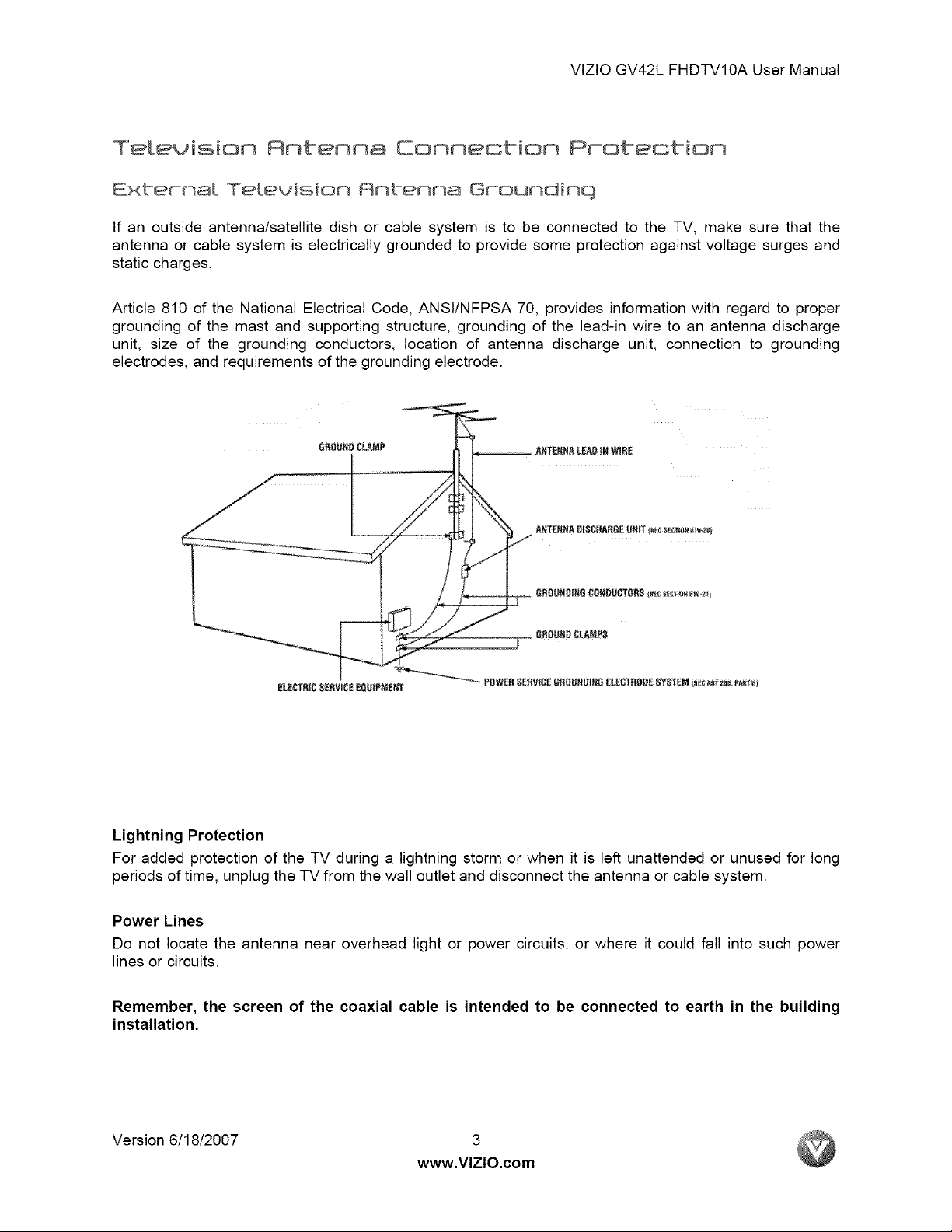
If an outside antenna/satellite dish or cable system is to be connected to the TV, make sure that the
antenna or cable system is electrically grounded to provide some protection against voltage surges and
static charges.
Article 810 of the National Electrical Code, ANSt/NFPSA 70, provides information with regard to proper
grounding of the mast and supporting structure, grounding of the lead-in wire to an antenna discharge
unit, size of the grounding conductors, location of antenna discharge unit, connection to grounding
electrodes, and requirements of the grounding electrode.
GROUNRCL,AMP
ELEC_RtC SERVICE EQOJPM_;,iT _ POWER SERVICE6ROL_RD|HG _LECTRODE SYSTEM _c _ z_ _:_ _1
Lightning Protection
For added protection of the TV during a lightning storm or when it is left unattended or unused for long
periods of time, unplug the TV from the wall outlet and disconnect the antenna or cable system.
Power Lines
Do not locate the antenna near overhead light or power circuits, or where it could fall into such power
lines or circuits.
Remember, the screen of the coaxial cable is intended to be connected to earth in the building
installation.
Version 6/18/2007 3
www.VlZlO.com
VlZtOGV42LFHDTV10AUserManual
Openinq the Packaqe
Your VtZlO GV42L FHDTVl0A and it accompanying accessories are carefully packed in a cardboard
carton that has been designed to protect it from transportation damage. Now you have opened the carton
check that the GV42L FHDTVl 0A is in good condition and that all of the accessories are included.
The GV42L FHDTVl0A weighs approximately 681bs and about 42" wide x 30" tall we strongly advise that
you have at least 2 people to unpack and install the HDTV.
The glass surface can easily be scratched or broken so please handle the product gently and never place
the HDTV with the glass facing downwards on a surface without protective padding.
IMPORTANT: Save the carton and packing material for future shipping.
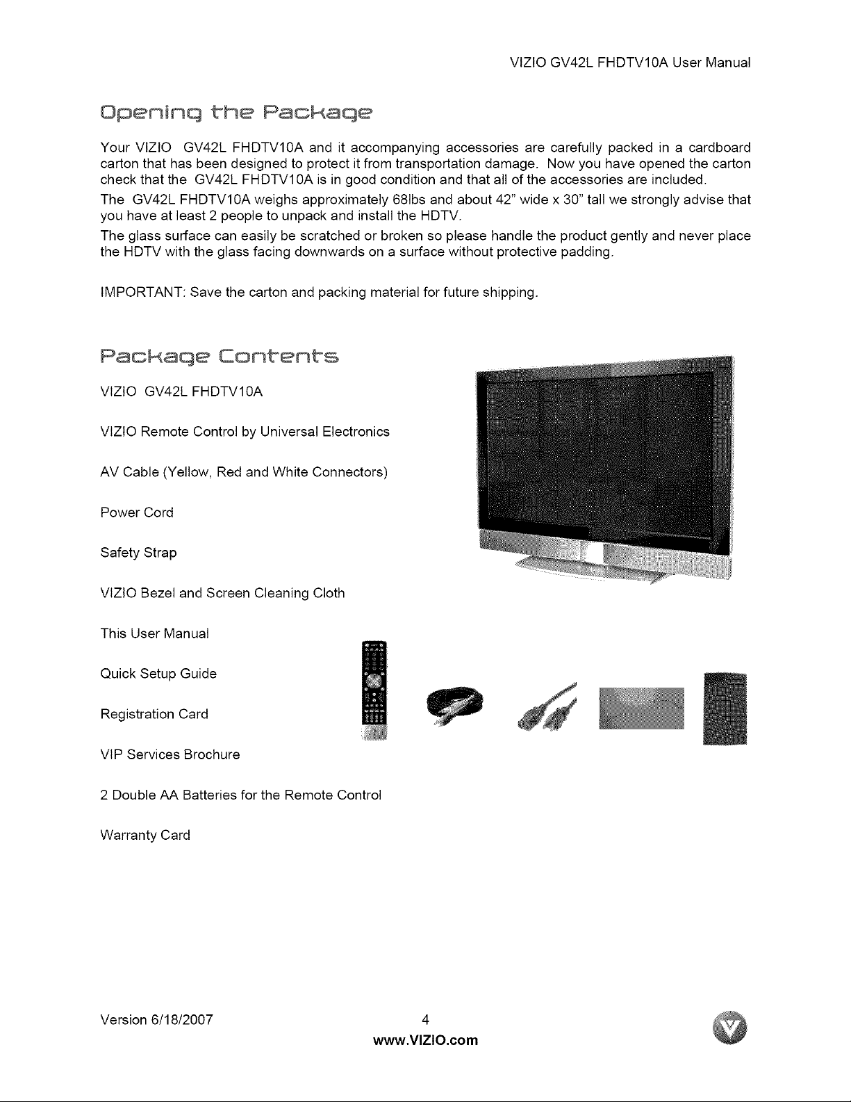
Packaqe Contents
VlZtO GV42L FHDTVl0A
VlZtO Remote Control by Universal Electronics
AV Cable (Yellow, Red and White Connectors)
Power Cord
Safety Strap
VlZtO Bezel and Screen Cleaning Cloth
This User Manual
Quick Setup Guide
Registration Card
VlP Services Brochure
2 Double AA Batteries for the Remote Control
Warranty Card
Version 6/18/2007 4
www.VlZlO.com
VlZlOGV42LFHDTV10AUserManual
Certified Accessories
GV42L FHDTVI®A TV are sold separateLv
Wall Mounts
High Definition Cables
Extra or replacement Remote
VtZlO also offers Installation Services and Extended Warranty Services for your VlZlO
FHDTVl0A
To purchase or inquire about additional accessories and services for your VlZlO product, visit our web
site at www.vizio.com or call us toll free at 888-VIZlOCE (888-849-4623)
GV42L
Insbattation Preparation
Please read this user manual carefully before installing your VlZtO HDTV.
The power consumption of the TV is about 280W, please use the power cord designated for TV. When
an extension cord is required, use one with the correct power rating. The cord must be grounded and the
grounding feature must not be defeated.
The TV should be installed on a flat surface to avoid tipping. For proper ventilation, you must allow space
between the back of the TV and the wall. tf you would like to mount your TV on the wall, please see
below 'Preparing Your LCD HDTV for Wall Mounting' for additional information. Avoid installing the TV in
places with high humidity, dust or smoke so as not to shorten the service life of the electronic components.
Install the TV in landscape orientation; any 90 ° clockwise or counter-clockwise installation may induce
poor ventilation and excessive component damage.
VlZlO offers professional installation services. Please contact VlZtO for more information on these
services at 888-VIZIOCE (888-849-4623) or www.vizio.com.
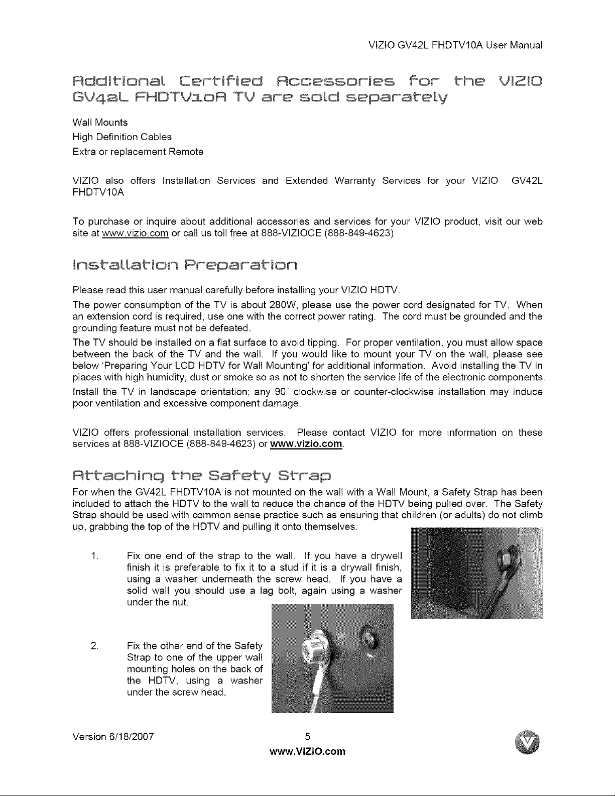
Rttachinq the Satiety Strap
For when the GV42L FHDTV10A is not mounted on the wall with a Wall Mount, a Safety Strap has been
included to attach the HDTV to the wall to reduce the chance of the HDTV being pulled over. The Safety
Strap should be used with common sense practice such as ensuring that children (or adults) do not climb
up, grabbing the top of the HDTV and pulling it onto themselves.
.
.
Version 6/18/2007 5
Fix one end of the strap to the wall. If you have a drywell
finish it is preferable to fix it to a stud if it is a drywall finish,
using a washer underneath the screw head. If you have a
solid wall you should use a lag bolt, again using a washer
under the nut.
Fix the other end of the Safety
Strap to one of the upper wall
mounting holes on the back of
the HDTV, using a washer
under the screw head.
www.VlZlO.com
VlZlOGV42LFHDTV10AUserManual
Preparinq Your Leo HOTV WaLL Nountinq
The VlZlO GV42L FHDTV10A can either be kept on the stand base or mounted on the wall for viewing, tf
you choose to mount the GV42L FHDTVl0A on the wall, please follow the instructions below for
removing the stand base.
To find the perfect mount for the VlZlO GV42L FHDTVl0A, browse VlZtO's certified mount selection at
www.VlZIO.com or call directly 888-VlZtOCE (888-849-4623).
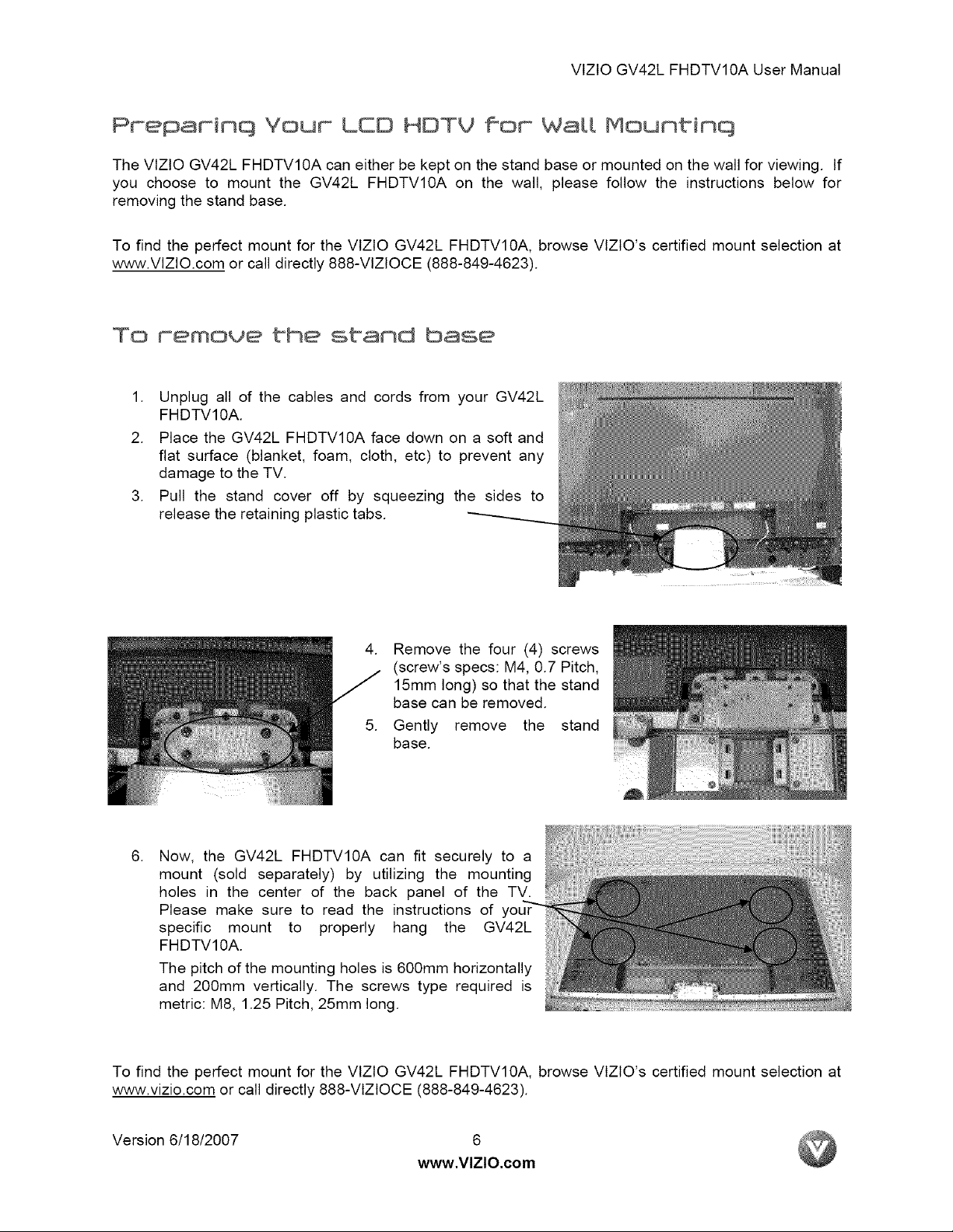
To remove the stand base
1. Unplug all of the cables and cords from your GV42L
FHDTVl0A.
2. Place the GV42L FHDTVl0A face down on a soft and
flat surface (blanket, foam, cloth, etc) to prevent any
damage to the TV.
3. Pull the stand cover off by squeezing the sides to
release the retaining plastic tabs.
4. Remove the four (4) screws
(screw's specs: M4, 0.7 Pitch,
15mm long) so that the stand
base can be removed.
5. Gently remove the stand
base.
.
Now, the GV42L FHDTVl0A can fit securely to a
mount (sold separately) by utilizing the mounting
holes in the center of the back panel of the TV.
Please make sure to read the instructions of
specific mount to properly hang the GV42L
FHDTVl0A.
The pitch of the mounting holes is 600mm horizontally
and 200mm vertically. The screws type required is
metric: M8, 1.25 Pitch, 25mm long.
To find the perfect mount for the VlZtO GV42L FHDTVl0A, browse VlZtO's certified mount selection at
www.vizio.com or call directly 888-VlZlOCE (888-849-4623).
Version 6/18/2007 6
www.VlZlO.com
VlZtOGV42LFHDTV10AUserManual
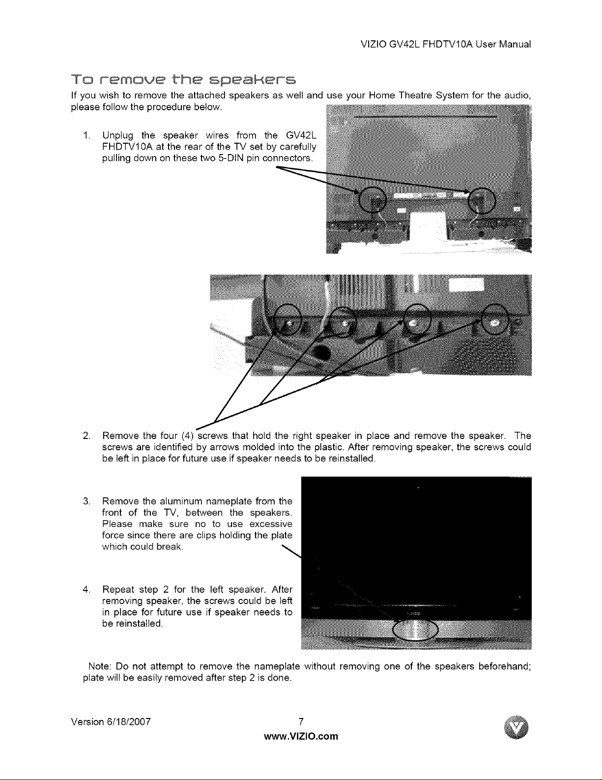
To memove the speakems
If you wish to remove the attached speakers as well and use your Home Theatre System for the audio,
please follow the procedure below.
1. Unplug the speaker wires from the GV42L
FHDTVl 0A at the rear of the TV set by carefully
pulling down on these two 5-DIN pin connectors.
2. Remove the four (4) screws that hold the right speaker in place and remove the speaker. The
screws are identified by arrows molded into the plastic. After removing speaker, the screws could
be left in place for future use if speaker needs to be reinstalled.
.
Remove the aluminum nameplate from the
front of the TV, between the speakers.
Please make sure no to use excessive
force since there are clips holding the plate
which could break.
.
Repeat step 2 for the left speaker. After
removing speaker, the screws could be left
in place for future use if speaker needs to
be reinstalled.
Note: Do not attempt to remove the nameplate without removing one of the speakers beforehand;
plate will be easily removed after step 2 is done.
Version 6/18/2007 7
www.VlZlO.com
VtZtOGV42LFHDTV10AUserManual
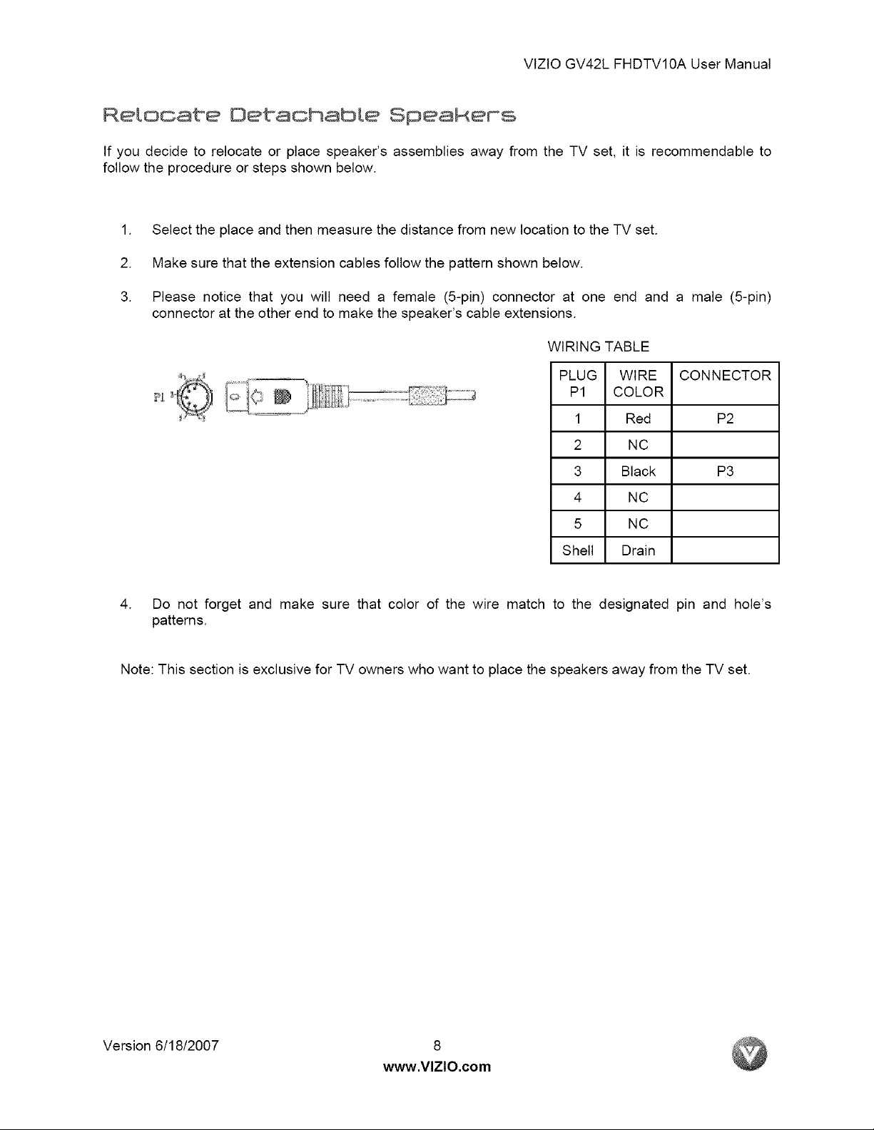
Relocate Detachable SpeaRems
If you decide to relocate or place speaker's assemblies away from the TV set, it is recommendable to
follow the procedure or steps shown below.
1. Select the place and then measure the distance from new location to the TV set.
2. Make sure that the extension cables follow the pattern shown below.
3. Please notice that you will need a female (5-pin) connector at one end and a male (5-pin)
connector at the other end to make the speaker's cable extensions.
WIRING TABLE
PLUG WIRE CONNECTOR
P1 COLOR
1 Red P2
2 NC
3 Black P3
4 NC
5 NC
Shell Drain
4. Do not forget and make sure that color of the wire match to the designated pin and hole's
patterns.
Note: This section is exclusive for TV owners who want to place the speakers away from the TV set.
Version 6/18/2007 8
www.VlZlO.com
VlZlOGV42LFHDTV10AUserManual
TabLe of Contents
ChBpt°er i Basic Contracts 8rid Oonneot°ioms ................................................................ii
1.1 Front Bezel ........................................................................................................................................................ 11
1.2 Right Side Panel Controls ................................................................................................................................. 11
1.3 Rear Panel Connections ................................................................................................................................... 12
1.4 VlZlO Universal Remote Control ....................................................................................................................... 14
1.4.1 Insertion of Batteries in the Remote Control .............................................................................................. 17
1.4.2 Remote Control Range .............................................................................................................................. 17
1.4.3 VlZlO Universal Remote Control Precautions ........................................................................................... 17
Chapter a Conneotinq Equipment ..................................................................................18
2.1 Which Video Connection Should I Use? ............................................................................................................ 18
2.2 Connecting Your Cable or Satellite Box ............................................................................................................ 19
2.2.1 Using HDMI ............................................................................................................................................... 19
2.2.2 Using Component Video ............................................................................................................................ 21
2.3 Connecting Coaxial (RF) ................................................................................................................................... 22
2.3.1 Using Your Antenna or Digital Cable for DTV ............................................................................................ 22
2.3.2 Using Your Antenna or Cable for TV ......................................................................................................... 23
2.3.3 Using the Antenna or Cable through your VCR ......................................................................................... 23
2.4 Connecting Your DVD Player ............................................................................................................................ 24
2.4.1 Using HDMI ............................................................................................................................................... 24
2.4.2 Using Component Video ............................................................................................................................ 26
2.4.3 Using S-Video (AVl) .................................................................................................................................. 27
2.4.4 Using Composite (AV2) Video ................................................................................................................... 28
2.5 Connecting Your VCR or Video Camera ........................................................................................................... 29
2.6 Connecting an external Receiver/Amp .............................................................................................................. 30
2.7 Connecting a PC Computer .............................................................................................................................. 31
2.7.1 Preset PC Resolutions ............................................................................................................................... 32
2.7.2 Resolution (1920x1080) through RGB (15-Pin VGA) Input ........................................................................ 32
Chapter 3 Settinq Up to Watch Te[euision ...................................................................33
3.1 Basic LCD HDTV Start Up ................................................................................................................................ 33
3.2 Watching a TV Program .................................................................................................................................... 36
3.3 Adjusting Basic LCD HDTV Settings ................................................................................................................. 36
3.4 Program Information .......................................................................................................................................... 37
Eh@ptem A Rdvanced Rd]ostment of HO'TV ................................................................... 38
4.1 Using the On Screen Display (OSD) ................................................................................................................. 38
4.2 DTV 1TV Input Picture Adjustment .................................................................................................................... 39
4.2.1 Picture Mode ............................................................................................................................................. 39
4.2.2 Backlight .................................................................................................................................................... 39
4.2.3 Contrast ..................................................................................................................................................... 40
4.2.4 Brightness .................................................................................................................................................. 40
4.2.5 Color .......................................................................................................................................................... 40
4.2.6 Tint ............................................................................................................................................................. 40
4.2.7 Sharpness ................................................................................................................................................. 41
4.2.8 Color Temperature ..................................................................................................................................... 41
4.3 Advanced Video ................................................................................................................................................ 42
4.3.1 DNR ........................................................................................................................................................... 42
4.3.2 Black Level Extender ................................................................................................................................. 42
4.3.3 White Peak Limiter ..................................................................................................................................... 42
4.3.4 CTI (Color Transient intensity) ................................................................................................................... 42
4.3.5 Flesh Tone ................................................................................................................................................. 42
4.3.6 Adaptive Luma ........................................................................................................................................... 42
4.3.7 DCR (Dynamic Contrast Ratio) .................................................................................................................. 42
4.4 DTV / TV Input Audio Adjustment ...................................................................................................................... 43
4.4.1 Volume ...................................................................................................................................................... 43
4.4.2 Bass ........................................................................................................................................................... 43
4.4.3 Treble ........................................................................................................................................................ 43
4.4.4 Balance ...................................................................................................................................................... 43
4.4.5 Surround .................................................................................................................................................... 44
4.4.6 Speakers ................................................................................................................................................... 44
4.5 DTV / TV Tuner Setup ....................................................................................................................................... 44
Version 6/18/2007 9
www.VlZlO.com
VlZtOGV42LFHDTV10AUserManual
4.5.1 Tuner Mode ............................................................................................................................................... 44
4.5.2 Auto Search .............................................................................................................................................. 44
4.5.3 Skip Channel ............................................................................................................................................. 44
4.5.4 Digital Audio Out ........................................................................................................................................ 45
4.5.5 Time Zone ................................................................................................................................................. 45
4.5.6 Daylight Saving .......................................................................................................................................... 45
4.6 DTV / TV Input Setup ........................................................................................................................................ 46
4.6.1 Language ................................................................................................................................................... 46
4.6.2 Sleep Timer ............................................................................................................................................... 46
4.6.3 Analog Closed Caption .............................................................................................................................. 46
4.6.4 Digital Closed Caption ............................................................................................................................... 46
4.6.5 Digital Closed Caption Style ...................................................................................................................... 47
4.6.6 PIP (Picture-in-Picture) .............................................................................................................................. 47
4.6.7 H/V Position ............................................................................................................................................... 47
4.6.8 Reset All Settings ...................................................................................................................................... 47
4.7 DTV / TV Input Parental Control ........................................................................................................................ 48
4.7.1 Channel Block ........................................................................................................................................... 48
4.7.2 TV Rating ................................................................................................................................................... 49
4.7.3 Movie Rating .............................................................................................................................................. 50
Blocked Unrated Programming ........................................................................................................................... 50
4.7.4 Change the Password ............................................................................................................................... 50
4.8 HDMI Input Picture Adjustment ......................................................................................................................... 51
4.9 HDMI Input Audio Adjustment ........................................................................................................................... 51
4.10 HDMI input Setup ............................................................................................................................................ 51
4.11 Video input Picture Adjustment ....................................................................................................................... 52
4.12 Video input Audio Adjustment ......................................................................................................................... 52
4.13 Video input Setup ............................................................................................................................................ 52
4.14 Video input Parental Control ........................................................................................................................... 53
4.15 PC Input Picture Adjustment ........................................................................................................................... 53
4.15.1 Auto Adjust .............................................................................................................................................. 53
4.15.2 Backlight .................................................................................................................................................. 53
4.15.3 Brightness ................................................................................................................................................ 54
4.15.4 Contrast ................................................................................................................................................... 54
4.15.5 Color Temperature ................................................................................................................................... 55
4.15.6 H-SIZE ..................................................................................................................................................... 55
4.15.7 H. Position ............................................................................................................................................... 55
4.15.8 V. Position ............................................................................................................................................... 55
4.15.9 Fine Tune ................................................................................................................................................ 55
4.16 PC Input Audio Adjustment ............................................................................................................................. 56
4.17 PC Input Setup ................................................................................................................................................ 56
4.18 Understanding Viewing Modes ........................................................................................................................ 57
4.18.1 Picture-in-Picture (PIP) Mode .................................................................................................................. 58
4.18.2 Using PIP/POP Feature ........................................................................................................................... 59
4.18.3 How to select PIP/POP ............................................................................................................................ 60
4.18.4 Setting the Sleep Timer ........................................................................................................................... 61
4.19 Programming the VlZIO Universal Remote Control ......................................................................................... 62
4.19.1 Programming for VCR ............................................................................................................................. 62
4.19.2 Programming for Cable Set-Top Box ....................................................................................................... 62
4.19.3 Programming for DVD Player .................................................................................................................. 63
4.19.4 Searching for Component Codes ............................................................................................................ 63
4.20 Using a Cable or Satellite Remote .................................................................................................................. 63
Chapter S Maintenance amd Troub_eshootimq .............................................................5 4
5.1 Maintenance ......................................................................................................................................................64
5.2 Troubleshooting Guide ...................................................................................................................................... 64
5.3 Telephone & Technical Support ........................................................................................................................ 66
5.4 Compliance ....................................................................................................................................................... 66
5.5 FCC Class B Radio Interference Statement ...................................................................................................... 67
Chapter 5 M_sGe_.[ameous h#ormat_om ...........................................................................68
6.1 Specifications .................................................................................................................................................... 68
6.2 Glossary - Standard Definitions ........................................................................................................................ 69
6.3 Index ................................................................................................................................................................. 70
6.4 Component Program Codes .............................................................................................................................. 72
Version 6/18/2007 10
www.VlZlO.com
VlZtOGV42LFHDTV10AUserManual
Chapter 1 Basic Cantrats and Connections
101 Front Bezet
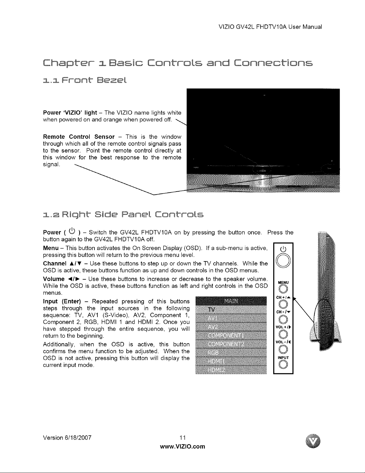
Power 'VlZlO' light - The VIZlO name lights white
when powered on and orange when powered off.
Remote Control Sensor - This is the window
through which all of the remote control signals pass
to the sensor. Point the remote control directly at
this window for the best response to the remote
signal.
1.2 Riqht Side Panet Controts
Power ( t,_ ) _ Switch the GV42L FHDTV10A on by pressing the button once. Press the
button again to the GV42L FHDTVl 0A off.
Menu - This button activates the On Screen Display (OSD). If a sub-menu is active, (3
pressing this button will return to the previous menu level.
Channel &IT - Use these buttons to step up or down the TV channels. While the ,_._
OSD is active, these buttons function as up and down controls in the OSD menus.
Volume </1_ - Use these buttons to increase or decrease to the speaker volume. _E_u
While the OSD is active, these buttons function as left and right controls in the OSD
menus.
Input (Enter) - Repeated pressing of this buttons
steps through the input sources in the following
sequence: TV, AVl (S-Video), AV2, Component 1,
Component 2, RGB, HDMI 1 and HDMI 2. Once you
have stepped through the entire sequence, you will
return to the beginning.
Additionally, when the OSD is active, this button
confirms the menu function to be adjusted. When the
OSD is not active, pressing this button will display the
current input mode.
CH ÷tA
CHJ'-
VOL+I)
©
VOL -/4
INPUT
Version 6/18/2007 11
www.VlZlO.com

103 Rear PameL Commeotioms
Lefit Hand Side Portion
T ,
.
SPEAKER - Connection for right speaker.
2.
3.
4.
7.
10.
AC IN - Plug-in the supplied AC Power Cord here.
SERVICE - This custom communication port is for factory service only.
HDMI 1 - Connect the primary source for digital video such as a DVD multimedia player or
set top box through this all digital connector. The white band on the rear of the TV Indicates
this connection.
Your VlZlO Certified HDMt and HDMI-DVl cables are available for purchase from
www.vizio.com or by calling 888-VIZlOCE (888-849-4623).
.
HDMI 2 - Connect the secondary source for digital video such as a DVD multimedia player or
set top box through this all digital connector. The white color band on the rear of the TV
indicates this connection. For users who want to connect to a DVl enabled device, use a
DVI-HDMI cable and connect the Analog Audio output of the device to the L+R AUDIO here..
Your VlZlO Certified HDMI and HDMI-DVt cables are available for purchase from
www.vizio.com or by calling 888-VIZtOCE (888-849-4623).
.
RGB PC - Connect the video and audio from a computer here. The blue color band on the
rear of the TV indicates this connection.
COMPONENT 1 (YPb/CbPr/Cr with Audio L/R) - Connect the primary source for
component video devices such as a DVD Player or set top box here. From left to right, use
green for Y, blue for Pb (or Cb), red for Pr (or Cr), white for left audio and red for right audio
inputs. The green color band on the rear of the TV indicates this connection.
.
COMPONENT 2 (YPb/CbPdCr with Audio L/R) - Connect the secondary source for
component video devices such as a DVD Player or set top box here. From left to right, use
green for Y, blue for Pb (or Cb), red for Pr (or Cr), white for left audio and red for right audio
inputs. The purple color band on the rear of the TV indicates this connection.
.
AV2 In - Connect the primary source for composite video devices, such as a VCR or video
game. Use the white and red connectors to connect the external audio from the same source.
The orange color band on the rear of the TV indicates this connection.
DTV/TV - Connect to an antenna or digital cable (out-of-the-wall, not from Cable Box) for
Digital TV.*
VlZtO GV42L FHDTV10A User Manual
_i¸_ L(_}?"_ _.....
Version 6/18/2007 12
www.VlZlO.com
Riqht Portion
VlZtOGV42LFHDTV10AUserManual
_DiO IN
L_
11.
12.
13.
14.
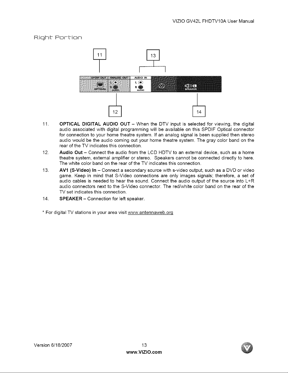
* For digital TV stations in your area visit www,antennaweb,orq
OPTICAL DIGITAL AUDIO OUT - When the DTV input is selected for viewing, the digital
audio associated with digital programming will be available on this SPDtF Optical connector
for connection to your home theatre system. If an analog signal is been supplied then stereo
audio would be the audio coming out your home theatre system. The gray color band on the
rear of the TV indicates this connection.
Audio Out - Connect the audio from the LCD HDTV to an external device, such as a home
theatre system, external amplifier or stereo. Speakers cannot be connected directly to here.
The white color band on the rear of the TV indicates this connection.
AVl (S-Video) In - Connect a secondary source with s-video output, such as a DVD or video
game. Keep in mind that S-Video connections are only images signals; therefore, a set of
audio cables is needed to hear the sound. Connect the audio output of the source into L+R
audio connectors next to the S-Video connector. The red/white color band on the rear of the
TV set indicates this connection.
SPEAKER - Connection for left speaker.
Version 6/18/2007 13
www.VlZlO.com
VlZlO GV42L FHDTV10A User Manual
YIZIO Universak Remote Control
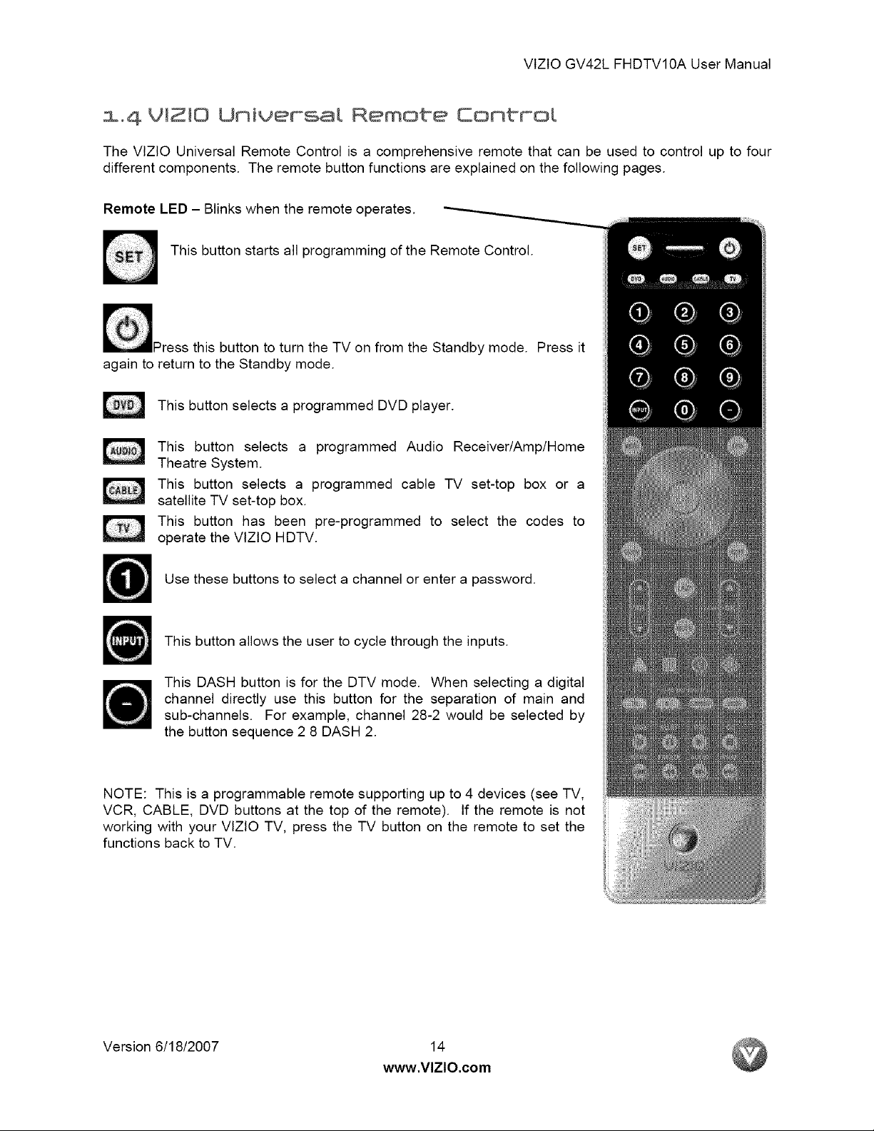
The VlZtO Universal Remote Control is a comprehensive remote that can be used to control up to four
different components. The remote button functions are explained on the following pages.
Remote LED - Blinks when the remote operates.
This button starts all programming of the Remote Control.
_ress this button to turn the TV on from the Standby mode. Press it
again to return to the Standby mode.
This button selects a programmed DVD player.
This button selects a programmed Audio Receiver/Amp/Home
Theatre System.
This button selects a programmed cable TV set-top box or a
satellite TV set-top box.
This button has been pre-programmed to select the codes to
operate the VlZtO HDTV.
Use these buttons to select a channel or enter a password.
This button allows the user to cycle through the inputs.
This DASH button is for the DTV mode. When selecting a digital
channel directly use this button for the separation of main and
sub-channels. For example, channel 28-2 would be selected by
the button sequence 2 8 DASH 2.
NOTE: This is a programmable remote supporting up to 4 devices (see TV,
VCR, CABLE, DVD buttons at the top of the remote). If the remote is not
working with your VtZtO TV, press the TV button on the remote to set the
functions back to TV.
Version 6/18/2007 14
www.VlZlO.com
VlZtOGV42LFHDTV10AUserManual
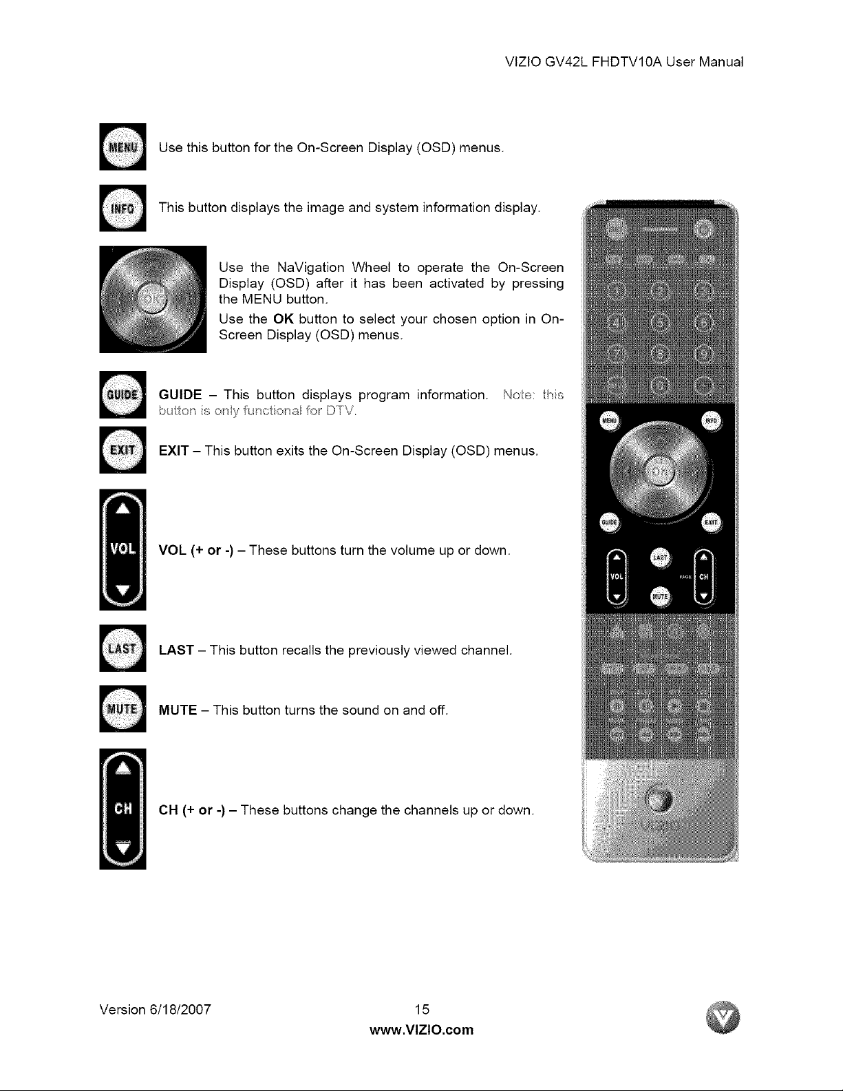
UsethisbuttonfortheOn-ScreenDisplay(OSD)menus.
Thisbuttondisplaystheimageandsysteminformationdisplay.
UsetheNaVigationWheeltooperatethe On-Screen
Display(OSD)afterit hasbeenactivatedby pressing
theMENUbutton.
UsetheOKbuttontoselectyourchosenoptionin On-
ScreenDisplay(OSD)menus.
6UIDE- Thisbuttondisplaysprograminformation.Noo: fiis
buto_iso_yu_ctio_ao_DTV.
EXIT- ThisbuttonexitstheOn-ScreenDisplay(OSD)menus.
VOL(+or-)- Thesebuttonsturnthevolumeupordown.
LAST- Thisbuttonrecallsthepreviouslyviewedchannel.
MUTE- Thisbuttonturnsthesoundonandoff.
CH(+or-)- Thesebuttonschangethechannelsupordown.
Version6/18/2007 15
www.VlZlO.com
VlZtOGV42LFHDTV10AUserManual
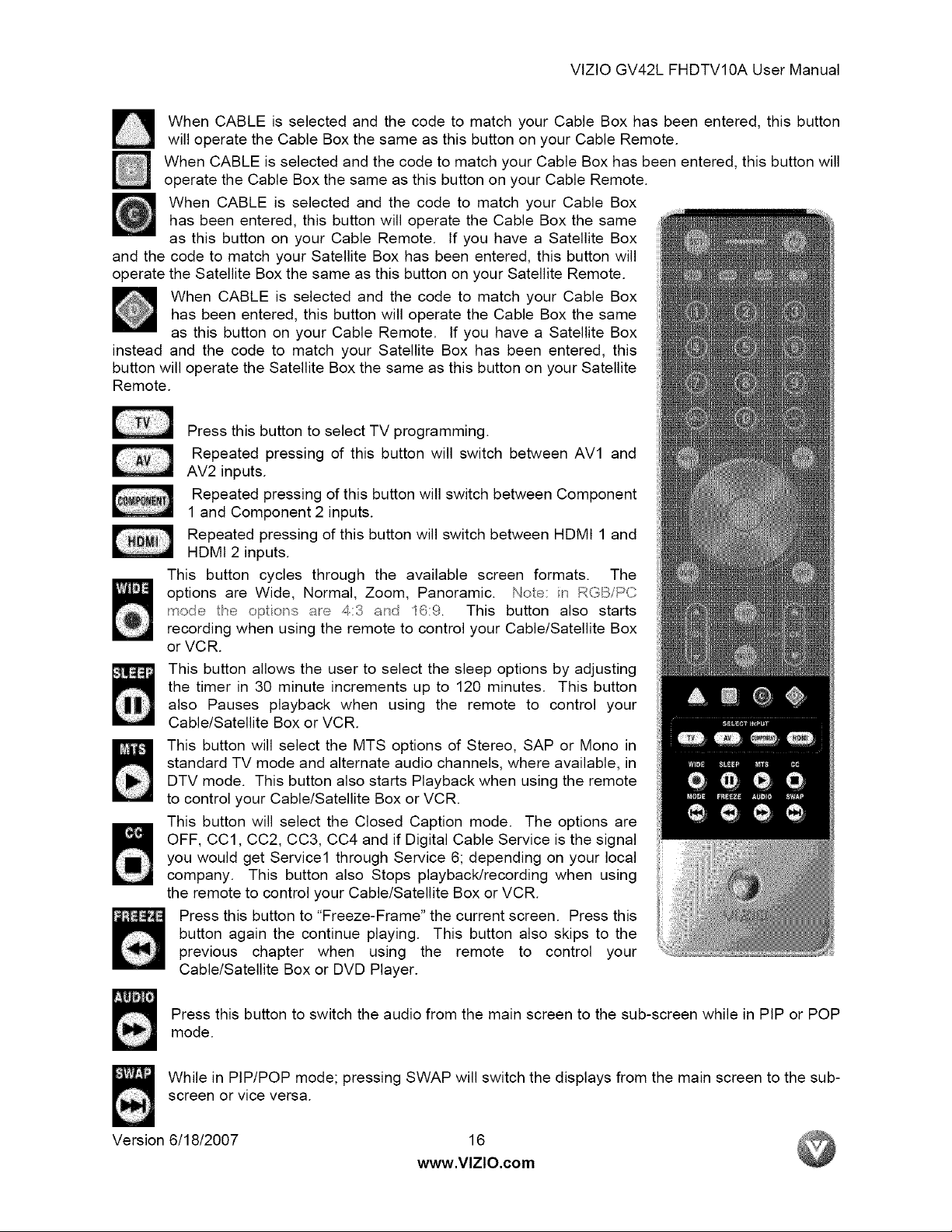
WhenCABLEisselectedandthecodetomatchyourCableBoxhasbeenentered,thisbutton
willoperatetheCableBoxthesameasthisbuttononyourCableRemote.
WhenCABLEisselectedandthecodetomatchyourCableBoxhasbeenentered,thisbuttonwill
operatetheCableBoxthesameasthisbuttononyourCableRemote.
WhenCABLEis selectedandthe codeto matchyourCableBox
hasbeenentered,thisbuttonwilloperatetheCableBoxthesame
asthisbuttononyourCableRemote.tfyouhavea SatelliteBox
andthecodetomatchyourSatelliteBoxhasbeenentered,thisbuttonwill
operatetheSatelliteBoxthesameasthisbuttononyourSatelliteRemote.
WhenCABLEis selectedandthecodeto matchyourCableBox
hasbeenentered,thisbuttonwilloperatetheCableBoxthesame
asthisbuttononyourCableRemote.Ifyouhavea SatelliteBox
insteadandthecodeto matchyourSatelliteBoxhasbeenentered,this
buttonwilloperatetheSatelliteBoxthesameasthisbuttononyourSatellite
Remote.
PressthisbuttontoselectTVprogramming.
Repeatedpressingof thisbuttonwillswitchbetweenAVl and
AV2inputs.
RepeatedpressingofthisbuttonwillswitchbetweenComponent
1andComponent2inputs.
RepeatedpressingofthisbuttonwillswitchbetweenHDMI1and
HDMI2 inputs.
Thisbuttoncyclesthroughthe availablescreenformats. The
optionsare Wide,Normal,Zoom,Panoramic.Noe: in RGB/PC
modefie opio_s are 4:3 a_d '16:9. This buttonalso starts
recordingwhenusingtheremotetocontrolyourCable/SatelliteBox
orVCR.
Thisbuttonallowstheusertoselectthesleepoptionsbyadjusting
thetimerin30minuteincrementsupto 120minutes.Thisbutton
also Pausesplaybackwhen usingthe remoteto controlyour
Cable/SatelliteBoxorVCR.
ThisbuttonwillselecttheMTSoptionsof Stereo,SAPor Monoin
standardTVmodeandalternateaudiochannels,whereavailable,in
DTVmode.ThisbuttonalsostartsPlaybackwhenusingtheremote
tocontrolyourCable/SatelliteBoxorVCR.
Thisbuttonwill selecttheClosedCaptionmode.Theoptionsare
OFF,CCl,CC2,CC3,CC4andifDigitalCableServiceisthesignal
youwouldgetService1throughService6;dependingonyourlocal
company.ThisbuttonalsoStopsplayback/recordingwhenusing
theremotetocontrolyourCable/SatelliteBoxorVCR.
Pressthisbuttonto"Freeze-Frame"thecurrentscreen.Pressthis
buttonagainthe continueplaying.Thisbuttonalsoskipstothe
previouschapterwhen using the remote to control your
Cable/SatelliteBoxorDVDPlayer.
Pressthisbuttontoswitchtheaudiofromthemainscreentothesub-screenwhileinPIPorPOP
mode.
WhileinPIP/POPmode;pressingSWAPwillswitchthedisplaysfromthemainscreentothesub-
screenorviceversa.
Version6/18/2007 16
www,VlZlO,com
VlZlOGV42LFHDTV10AUserManual
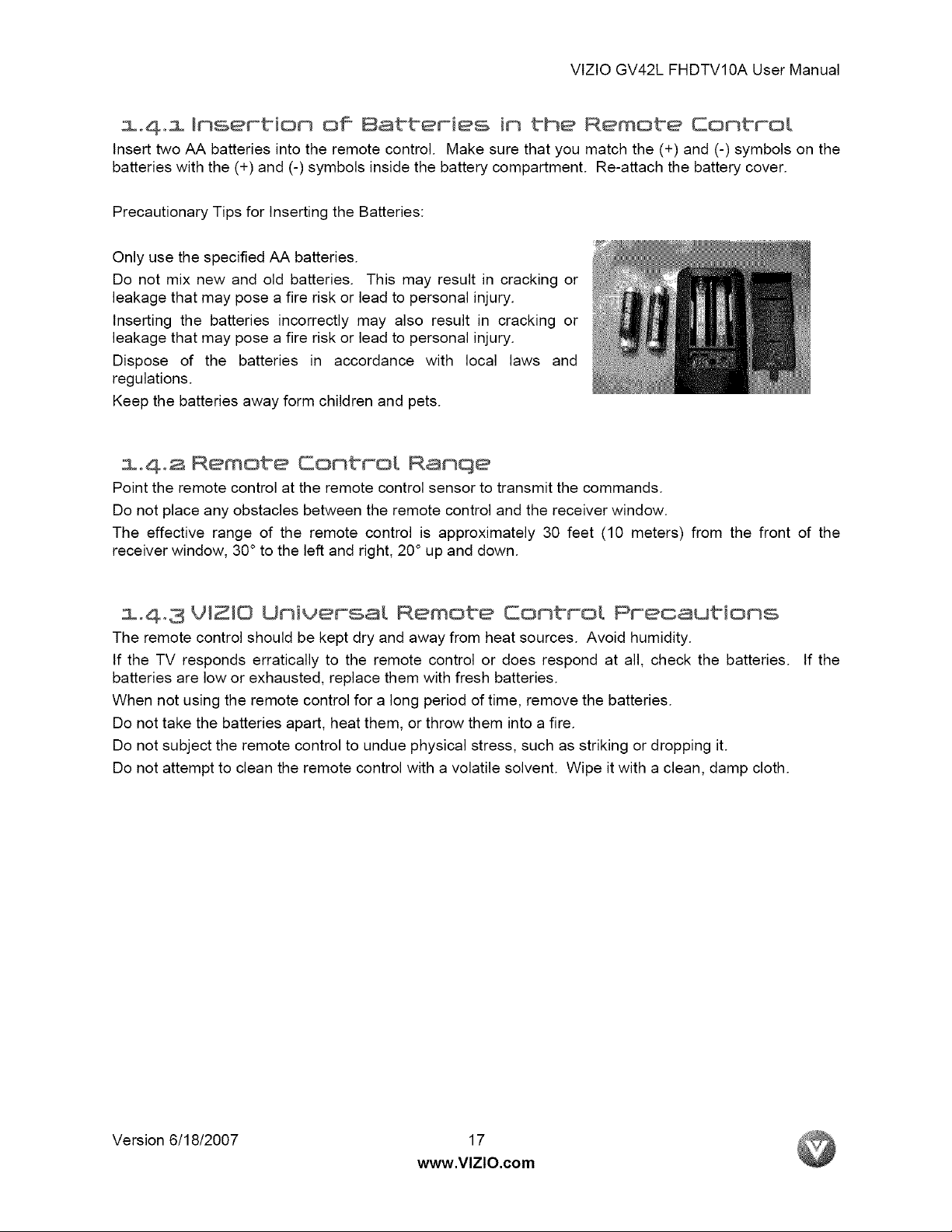
m,4,m Insertion of Batteries in the Remote EontroL
Insert two AA batteries into the remote control. Make sure that you match the (+) and (-) symbols on the
batteries with the (+) and (-) symbols inside the battery compartment. Re-attach the battery cover.
Precautionary Tips for Inserting the Batteries:
Only use the specified AA batteries.
Do not mix new and old batteries. This may result in cracking or
leakage that may pose a fire risk or lead to personal injury.
Inserting the batteries incorrectly may also result in cracking or
leakage that may pose a fire risk or lead to personal injury.
Dispose of the batteries in accordance with local laws and
regulations.
Keep the batteries away form children and pets.
1o4o2 Remote Control Ranqe
Point the remote control at the remote control sensor to transmit the commands.
Do not place any obstacles between the remote control and the receiver window.
The effective range of the remote control is approximately 30 feet (10 meters) from the front of the
receiver window, 30° to the left and right, 20 ° up and down.
1.4,3 VIZIO Universal Remote Control Precautions
The remote control should be kept dry and away from heat sources. Avoid humidity.
If the TV responds erratically to the remote control or does respond at all, check the batteries. If the
batteries are low or exhausted, replace them with fresh batteries.
When not using the remote control for a long period of time, remove the batteries.
Do not take the batteries apart, heat them, or throw them into a fire.
Do not subject the remote control to undue physical stress, such as striking or dropping it.
Do not attempt to clean the remote control with a volatile solvent. Wipe it with a clean, damp cloth.
Version 6/18/2007 17
www.VlZlO.com
VtZtOGV42LFHDTV10AUserManual
Chapter Connectinq Equipment
2oi Which Video Connecbion Shou{d I Use?
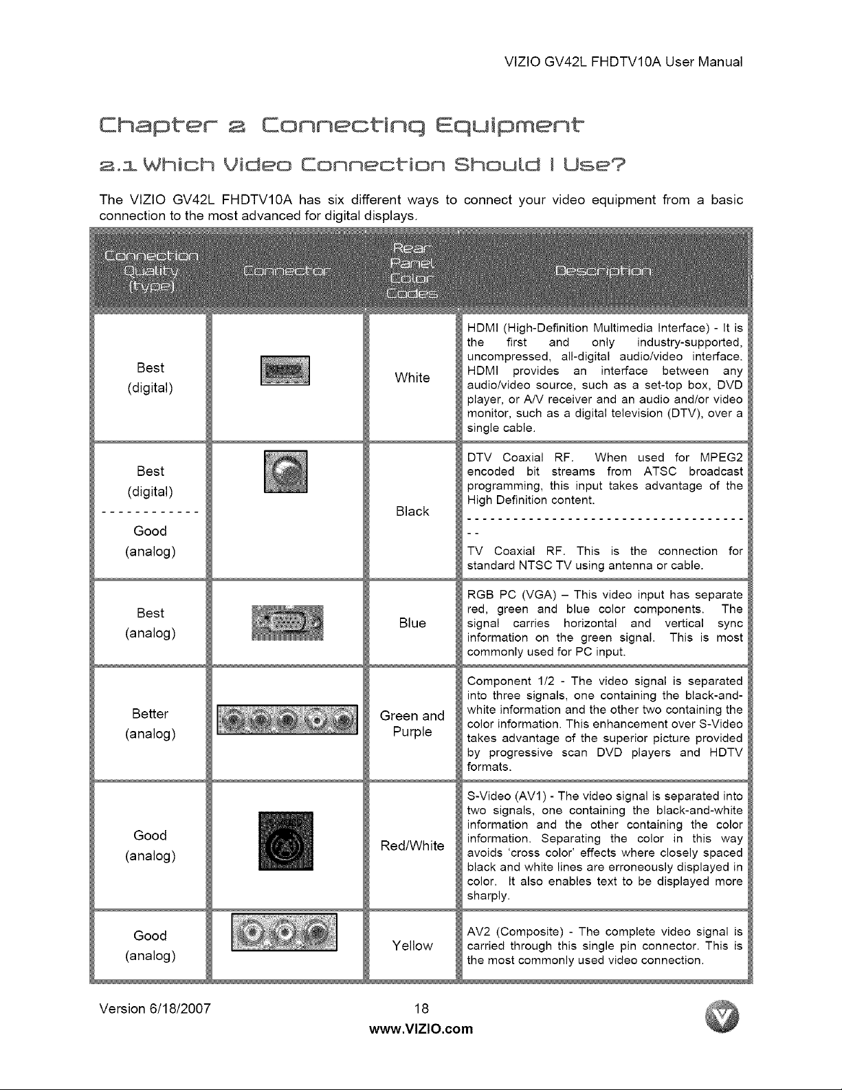
The VIZIO GV42L FHDTVIOA has sixdifferentways to connectyour video equipment from a basic
connectiontothemost advanced fordigitaldisplays.
HDMI (High-Definition Multimedia Interface) - It is
the first and only industry-supported,
Best
(digital)
Best
(digital)
Good
(analog)
White
Black
uncompressed, all-digital audio/video interface.
HDMI provides an interface between any
audiolvideo source, such as a set-top box, DVD
player, or A/V receiver and an audio and/or video
monitor, such as a digital television (DTV), over a
single cable.
DTV Coaxial RF. When used for MPEG2
encoded bit streams from ATSC broadcast
programming, this input takes advantage of the
High Definition content.
TV Coaxial RF. This is the connection for
standard NTSC TV using antenna or cable.
Best
(analog)
Better
(analog)
Good
(analog)
Good
(analog)
Blue
Green and
Purple
Red/White
Yellow
RGB PC (VGA) - This video input has separate
red, green and blue color components. The
signal carries horizontal and vertical sync
information on the green signal. This is most
commonly used for PC input.
Component 1/2 - The video signal is separated
into three signals, one containing the black-and-
white information and the other two containing the
color information. This enhancement over S-Video
takes advantage of the superior picture provided
by progressive scan DVD players and HDTV
formats.
S-Video (AVl) - The video signal is separated into,
two signals, one containing the black-and-white
information and the other containing the color
information. Separating the color in this way
avoids 'cross color' effects where closely spaced
black and white lines are erroneously displayed in
color. It also enables text to be displayed more
sharply.
AV2 (Composite) - The complete video signal is
carried through this single pin connector. This is
the most commonly used video connection.
Version 6/18/2007
18
www.VlZlO.com

VlZtOGV42LFHDTV10AUserManual
Noe: Formorefnlo_dero }e QuickStarGufde
2°2 Conneotinq Your Cable or Sate[Ute @OH
2o2ol Using HOM_
Cable and Satellite Boxes that have a HDMI digital interface should be connected to the HDMI input of
the LCD HDTV for optimal results.
Connectinq your Cabte or SatelUte Box {Best}
.
Turn off the power to the LCD HDTV and HDTV Set-Top Box.
2.
4.
Version 6/18/2007 19
Connect a HDMI cable to the HDMI output of your HDTV Set-Top Box and the other end to
the HDMI Input (white color area) at the rear of the LCD HDTV.
.
Turn on the power to the LCD HDTV and HDTV Set-Top Box.
Select HDMI using the INPUT button on the remote or side of the LCD HDTV, or directly by
pressing the HDMI button on the Remote Control.
www,VlZlO,com
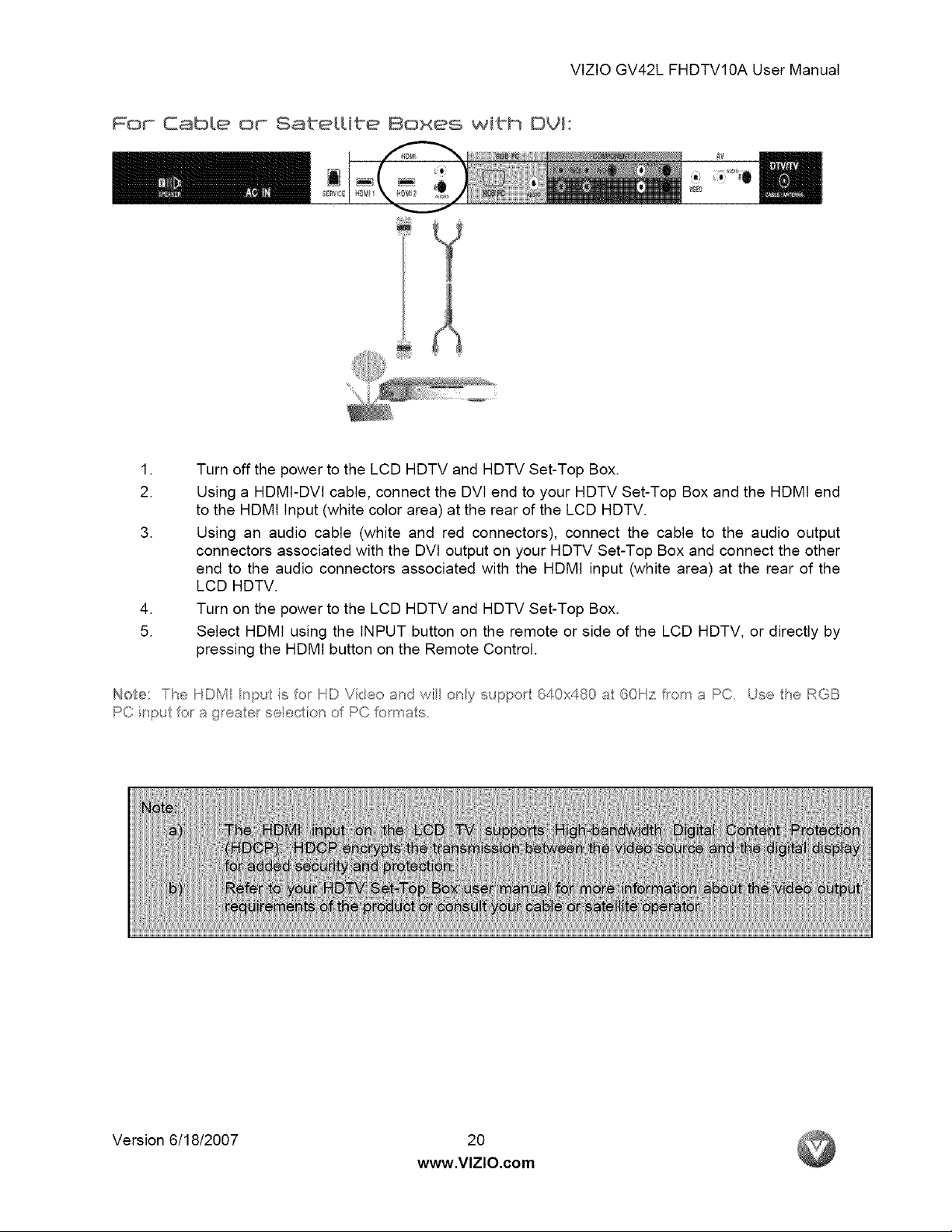
For Gable or SatelUte Boxes with Dgl:
.
Turn off the power to the LCD HDTV and HDTV Set-Top Box.
2.
.
.
5.
Using a HDMI-DVl cable, connect the DVl end to your HDTV Set-Top Box and the HDMI end
to the HDMI Input (white color area) at the rear of the LCD HDTV.
Using an audio cable (white and red connectors), connect the cable to the audio output
connectors associated with the DVl output on your HDTV Set-Top Box and connect the other
end to the audio connectors associated with the HDMI input (white area) at the rear of the
LCD HDTV.
Turn on the power to the LCD HDTV and HDTV Set-Top Box.
Select HDMI using the INPUT button on the remote or side of the LCD HDTV, or directly by
pressing the HDMI button on the Remote Control.
VlZlOGV42LFHDTV10AUserManual
Us
Note: The HDM nPU is o_ HD Vkeo and wil ory suppo_ 640x480 a 60Hz fro_ a PC. Use tie RGB
PCi_pu otagteaetseeclior o PC_omas.
Version 6/18/2007 20
www.VlZlO.com
VtZtOGV42LFHDTV10AUserManual
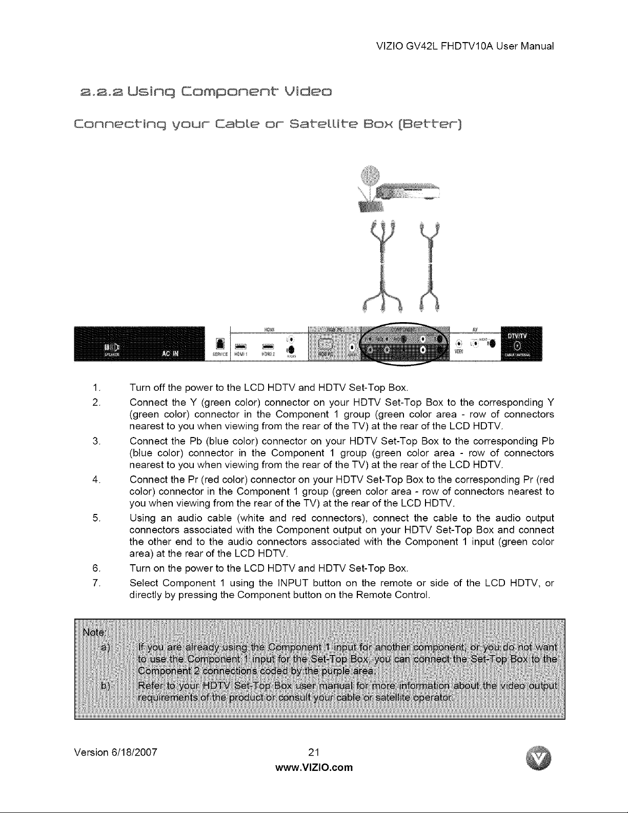
,_:;++i++++I
I.
2.
Turn off the power to the LCD HDTV and HDTV Set-Top Box.
Connect the Y (green color) connector on your HDTV Set-Top Box to the corresponding Y
(green color) connector in the Component 1 group (green color area - row of connectors
nearest to you when viewing from the rear of the TV) at the rear of the LCD HDTV.
.
Connect the Pb (blue color) connector on your HDTV Set-Top Box to the corresponding Pb
(blue color) connector in the Component 1 group (green color area - row of connectors
nearest to you when viewing from the rear of the TV) at the rear of the LCD HDTV.
.
Connect the Pr (red color) connector on your HDTV Set-Top Box to the corresponding Pr (red
color) connector in the Component 1 group (green color area - row of connectors nearest to
you when viewing from the rear of the TV) at the rear of the LCD HDTV.
.
Using an audio cable (white and red connectors), connect the cable to the audio output
connectors associated with the Component output on your HDTV Set-Top Box and connect
the other end to the audio connectors associated with the Component 1 input (green color
area) at the rear of the LCD HDTV.
.
Turn on the power to the LCD HDTV and HDTV Set-Top Box.
7.
Select Component 1 using the INPUT button on the remote or side of the LCD HDTV, or
directly by pressing the Component button on the Remote Control.
Version 6/18/2007 21
www,VlZlO,com
VtZtO GV42L FHDTV10A User Manual
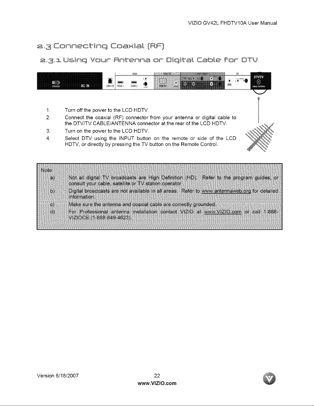
a+3 Connectinq Coaxia!. [RF]
a+3+l Usinq Your Antenna or Oiqital CabLe for OTV
+++++++++41
I.
2.
Turn off the power to the LCD HDTV.
Connect the coaxial (RF) connector from your antenna or digital cable to
the DTV/TV CABLE/ANTENNA connector at the rear of the LCD HDTV.
+
Turn on the power to the LCD HDTV.
4.
Select DTV using the INPUT button on the remote or side of the LCD
HDTV, or directly by pressing the TV button on the Remote Control.
Version 6/18/2007 22
www.VlZlO.com
VtZtOGV42LFHDTV10AUserManual
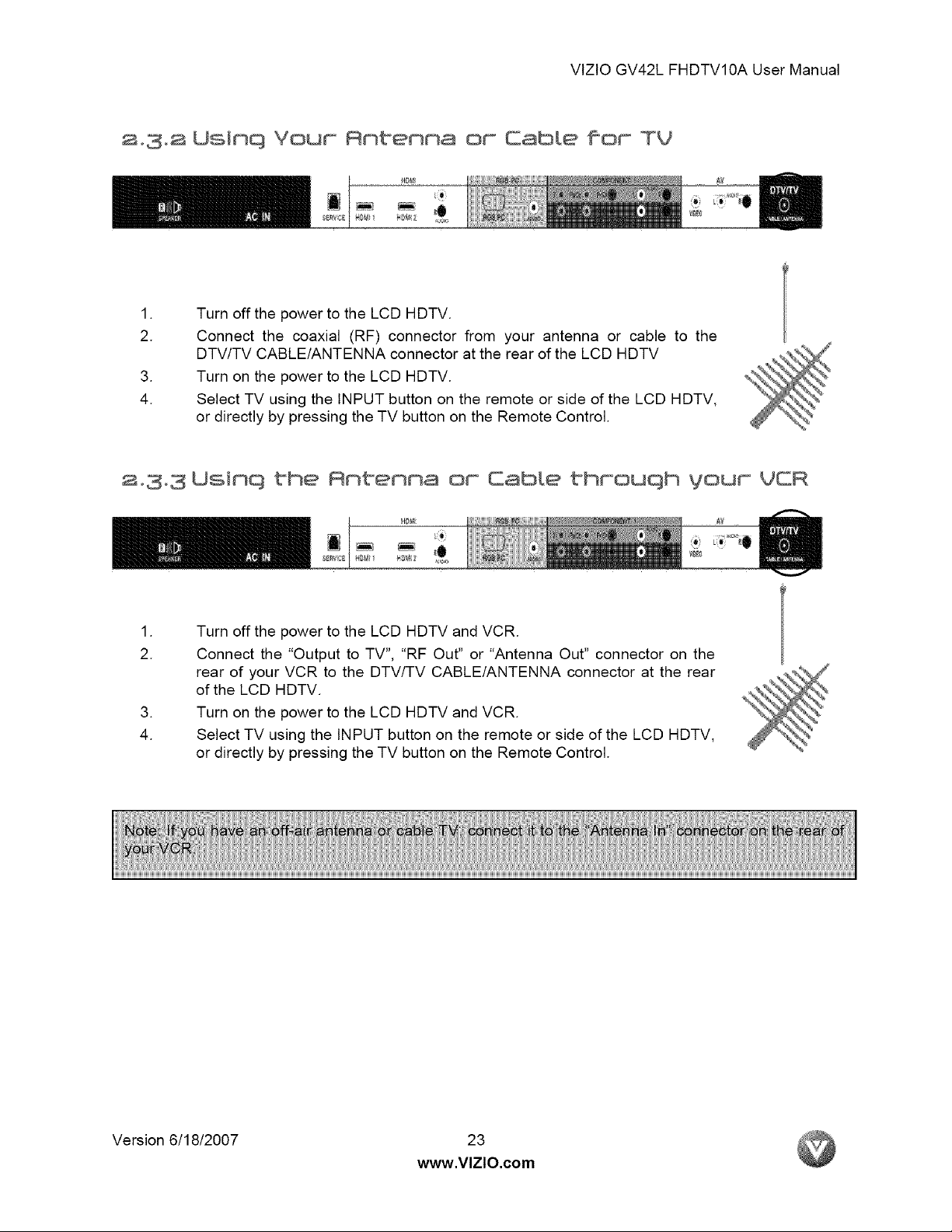
a+3°a UsinQ Your Antenna
or Cable for TV
++++I+FS@
I.
2.
Turn off the power to the LCD HDTV.
Connect the coaxial (RF) connector from your antenna or cable to the
DTV/TV CABLE/ANTENNA connector at the rear of the LCD HDTV
.
Turn on the power to the LCD HDTV.
4.
Select TV using the INPUT button on the remote or side of the LCD HDTV,
or directly by pressing the TV button on the Remote Control.
a+3°3 Uslnq the Antenna or Cable throuqh your VCR
++;++++@
I.
2.
Turn off the power to the LCD HDTV and VCR.
Connect the "Output to TV", "RF Out" or "Antenna Out" connector on the
rear of your VCR to the DTV/TV CABLE/ANTENNA connector at the rear
of the LCD HDTV.
.
Turn on the power to the LCD HDTV and VCR.
4.
Select TV using the INPUT button on the remote or side of the LCD HDTV,
or directly by pressing the TV button on the Remote Control.
Version 6/18/2007 23
www.VlZlO.com
VlZtOGV42LFHDTV10AUserManual
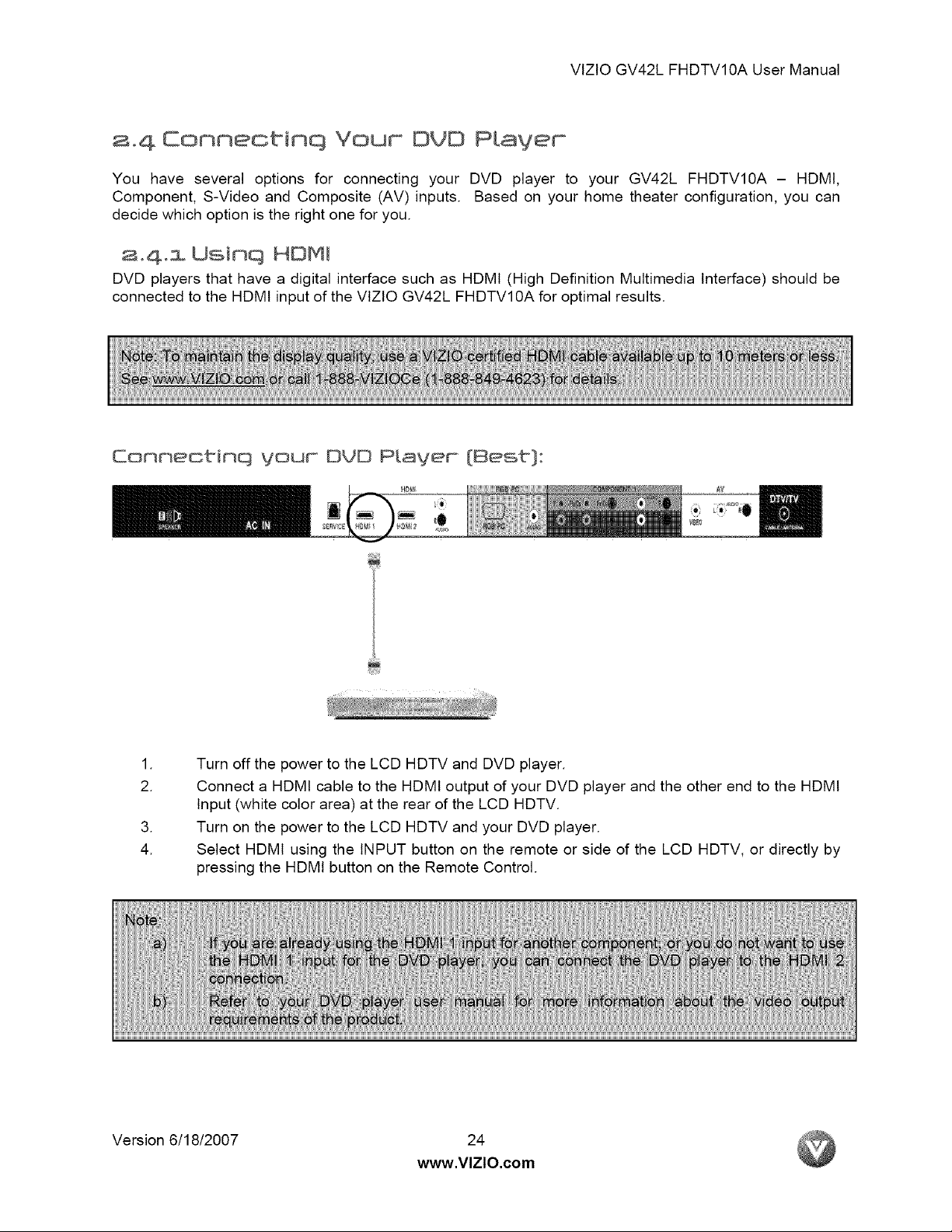
a.4 Connectinq Your DVD PLayer
You have several options for connecting your DVD player to your GV42L FHDTVl0A - HDMt,
Component, S-Video and Composite (AV) inputs. Based on your home theater configuration, you can
decide which option is the right one for you.
2,4,1 Usinq HOMJ
DVD players that have a digital interface such as HDMI (High Definition Multimedia Interface) should be
connected to the HDMI input of the VlZtO GV42L FHDTVl0A for optimal results.
Eonnectinq your OrB PLayer {Best}:
aBW_
I.
2.
Turn off the power to the LCD HDTV and DVD player.
Connect a HDMI cable to the HDMI output of your DVD player and the other end to the HDMI
Input (white color area) at the rear of the LCD HDTV.
.
Turn on the power to the LCD HDTV and your DVD player.
4.
Select HDMI using the INPUT button on the remote or side of the LCD HDTV, or directly by
pressing the HDMI button on the Remote Control.
Version 6/18/2007 24
www.VlZlO.com
 Loading...